

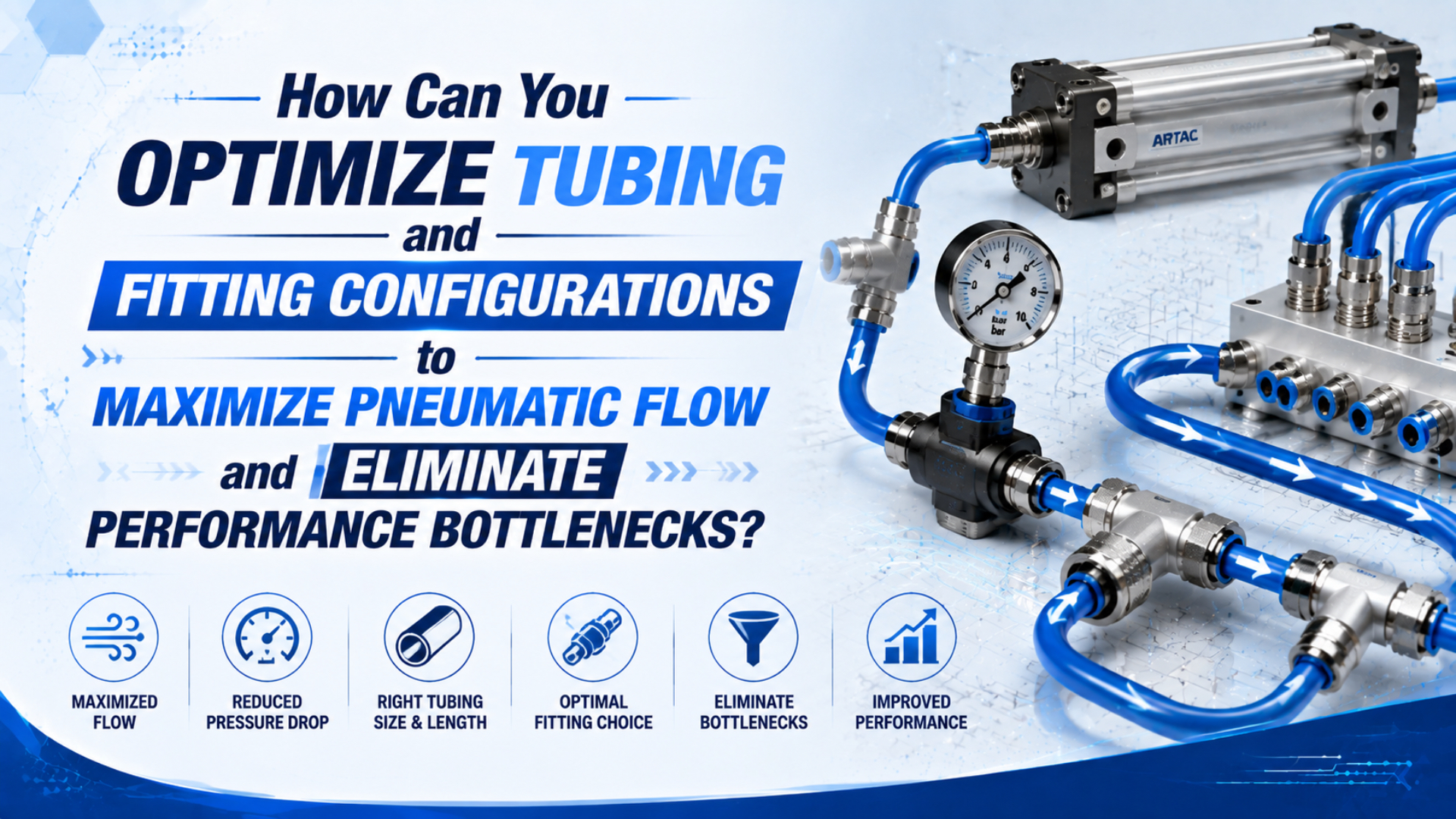
Optimize pneumatic tubing and fittings as one valve-to-actuator branch, not as separate catalogue items. Define the peak flow event, check every internal passage on the supply and exhaust sides, then measure pressure during the failed cycle. A larger tube helps only when the tube or one of its connections is the limiting part.
This article covers branch integration and commissioning. Use the separate pneumatic fitting selection guide for model-level material, seal, thread, and connector comparisons.
Key Takeaways
- ISO 14743 covers complete push-in connector assemblies for 3-16 mm OD thermoplastic tube.
- Size from peak demand, actual tube ID, length, fitting data, and allowable dynamic pressure loss.
- Prove the result with synchronized pressure and cycle-time measurements, not an idle regulator gauge.
Publisher information is available on the About Us page. Send technical questions or correction requests through Contact.
What Does an Optimized Tubing and Fitting Branch Include?
ISO 14743:2020 specifies test methods for complete push-in connector assemblies used with thermoplastic tube from 3 to 16 mm outside diameter. That scope confirms that the tube and connector work as an assembly; it does not turn the printed tube size into a flow rating (ISO 14743, 2020).
An optimized branch includes every passage that air crosses during the required motion:
- machine supply, isolation, filtration, and regulation, including any shared header affected by concurrent actuator, vacuum, or blow-off demand elsewhere on the machine;
- manifold and directional valve;
- flow control or check valve;
- threaded adapters and push-in connectors;
- tube ID, length, bends, and branches;
- cylinder ports, chambers, return tube, valve exhaust, and silencer.
That last item is easy to miss.
A cylinder can fill through an adequate supply line and still retract slowly because exhaust air is trapped by a small fitting, closed meter-out control, restricted valve passage, or loaded silencer. Supply and exhaust are two different flow paths.
Pneumatic branch optimization is the process of matching peak demand to the complete supply and exhaust routes while preserving the pressure, response time, safety, and serviceability required at the actuator. It is not a rule that every component should have the largest available port.
The flow coefficient Cv guide and choked-flow diagnostic guide provide the component-level background for this branch review.
Start With the Peak Flow Event
CAGI states that most well-designed compressed-air systems have no more than 10% pressure drop between compressor discharge and any point of use. That plant-wide value is a screening ceiling, not an automatic allowance for one machine branch. Start with the actuator’s minimum pressure and cycle-time requirement (CAGI Pressure Drop Brief, accessed 2026).
Describe the event before selecting tube or fittings. A usable demand record includes:
| Required input | What to record | Why it changes the branch |
|---|---|---|
| Motion | extension or retraction, stroke, target time | identifies the active valve and exhaust paths |
| Actuator | bore, rod diameter, chamber volume | establishes how much air must enter or leave |
| Load | force direction, friction, acceleration | sets the minimum dynamic pressure at the cylinder |
| Simultaneous demand | other cylinders, blow-off, vacuum generators | exposes shared manifold and supply limitations |
| Supply condition | minimum upstream pressure during production | prevents sizing from a favorable idle reading |
| Environment | temperature, washdown, chemicals, vibration | controls tube, seal, fitting, and support selection |
Average flow can hide a short peak.
For example, two actuators moving together may load a common manifold more heavily than either branch does alone.
Do not begin with a universal tube-to-orifice ratio. Begin with the required chamber flow, target stroke time, and lowest acceptable cylinder pressure during motion.
The useful design quantity is a pressure budget. Allocate the available difference between minimum machine supply and minimum actuator pressure across the FRL, valve, fittings, tubing, controls, and exhaust path. If every part is allowed to consume the full budget, the assembled circuit will fail even though each component looked acceptable alone.
How Should You Size Tube ID Without a 4:1 Shortcut?
ISO 14743 covers connector assemblies for tube outside diameters from 3 to 16 mm, but it does not prescribe one inside diameter for every actuator. Flow area comes from tube ID, which changes with wall thickness and material. Record both OD and ID before using any velocity or pressure-drop calculation (ISO 14743, 2020).
Use this sequence:
- Estimate peak flow for extension and retraction, including shared demand from every device that can move at the same time.
- Obtain the actual tube ID.
- Calculate from ID, length, pressure, and flow.
- Add only documented equivalent fitting length.
- Compare against the branch budget.
- Check ports and fittings before selecting the next tube.
The Tube ID Calculator is useful for an initial flow-velocity screen. It doesn’t replace the supplier’s pressure-flow data for valves, controls, connectors, or silencers.
Tube length matters twice.
First, wall friction raises steady pressure loss. Second, the switched tube volume must be filled and exhausted every cycle. A remote valve can therefore slow response even when steady-state pressure loss looks modest.
Why Can Fittings Become the Hidden Restriction?
SMC lists 26.1 mm2 effective area for a 5/16-inch KQ2H straight connector and 21.6 mm2 for the comparable KQ2L elbow with nylon tube and a Uni 1/4 connection. The 17% difference shows why tube size and thread label alone cannot predict fitting capacity (SMC KQ2, accessed 2026).
Compare the exact configured part.
The relevant fields are:
| Fitting detail | Flow question | Reliability question |
|---|---|---|
| Tube OD and material | what effective area applies to this combination? | is the tube hardness and material approved? |
| Actual internal passage | is it smaller than the tube ID or component port? | can contamination or insertion reduce it further? |
| Geometry | straight, elbow, Y, reducer, banjo, or swivel? | will side load or movement damage the connection? |
| Thread and seal | does the thread throat restrict the path? | gasket, face seal, coating, or approved sealant? |
| Test basis | inlet pressure, outlet pressure, temperature, flow reference | are the compared data based on the same conditions? |
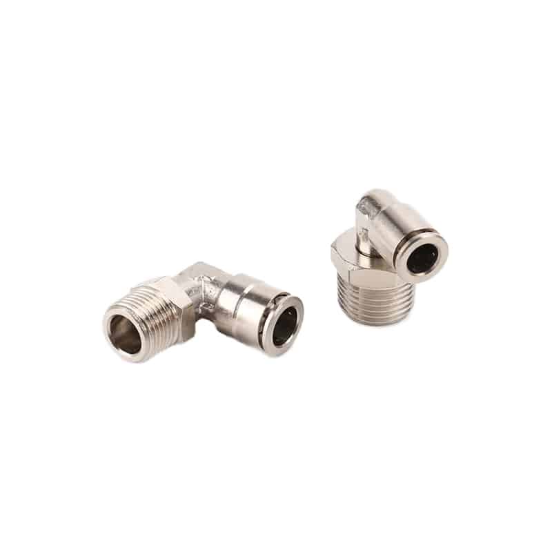
An elbow is not automatically unacceptable, and a straight fitting is not automatically full flow. Geometry, internal support sleeves, seals, thread size, and the supplier’s design determine the actual passage. Compare effective area, sonic conductance and critical ratio, or a pressure-flow curve under matched conditions.
Avoid using a liquid Cv shortcut to promise compressed-air flow. Gas flow depends on absolute upstream and downstream pressure, temperature, gas properties, and whether the restriction is subsonic or choked. When a catalogue lists only Cv, retain the supplier’s stated test basis and use it for comparison within that basis.
A Branch Flow-Budget Workflow
ISO 6358-3 describes steady-state calculations for systems of pneumatic components and piping whose individual flow characteristics are already known. The standard covers both subsonic and choked behavior and was confirmed as current in 2025. Reliable system math therefore begins with valid component data, not assumed universal coefficients (ISO 6358-3, 2014).
Use a configuration table that follows the real air path:
| Order | Component | Evidence to collect | Release check |
|---|---|---|---|
| 1 | machine supply | minimum dynamic pressure and concurrent demand | supply remains above branch requirement |
| 2 | FRL | rated flow and differential pressure | clean element at peak event |
| 3 | manifold and valve | configured port path, C and b, Cv, or pressure-flow curve | both directions and exhaust paths checked |
| 4 | controls | meter-in or meter-out setting, check-valve direction | stable speed without trapped exhaust |
| 5 | fittings | exact models and tested flow data | no smaller hidden throat |
| 6 | tubing | material, OD, ID, length, route | calculated loss and switched volume acceptable |
| 7 | cylinder | port, minimum dynamic pressure, stroke result | required force and time achieved |
| 8 | exhaust | valve path and silencer condition | back pressure remains acceptable |
Add losses in the order the air experiences them, but do not invent a simple 1/Cv series rule. ISO 6358-3 uses pneumatic component characteristics because the relationship changes between subsonic and choked regions. If a component lacks usable data, mark it as unknown and measure it.
Keep two budgets on the same sheet: a steady-flow pressure budget and a response-volume budget. The first finds friction and local restrictions. The second captures the time needed to pressurize tube and chamber volume. This separates a long-line response delay from a hard flow ceiling.
How Do You Find the Bottleneck During the Failed Cycle?
DOE states that maximum supply-to-point-of-use pressure drop occurs when compressed-air flow and temperature are highest. It recommends obtaining component pressure-drop data under those conditions. Measure the machine during the motion that fails; an idle gauge cannot reveal a restriction that appears only at peak demand (DOE Sourcebook, 2003).
Use two synchronized pressure sensors.
Record them against the machine-cycle signal:
- Reproduce the fault at normal production load.
- Install one suitable sensor before the suspected restriction and a second after it, using a matched sample rate and time base without adding another meaningful restriction.
- Record both traces through the full cycle.
- Note minimum cylinder pressure and differential.
- Change one item.
- Repeat and compare pressure, timing, repeatability, and cushioning.
A large dynamic differential across one part makes it a strong restriction suspect. A low pressure at both sensors points farther upstream. Normal supply-side pressure with high exhaust back pressure points to the return path, not the inlet tube.
For a broader plant-to-machine diagnosis, use the compressed-air pressure-drop troubleshooting guide. If most loss appears across the directional valve, follow the pneumatic valve pressure-drop guide before replacing nearby tubing.
Installation Details That Protect Flow
Festo lists reference insertion depths of 15, 17, 18, 20.5, and 23.5 mm for its standard QS fittings with 4, 6, 8, 10, and 12 mm tube OD. Those model-specific values illustrate why full insertion must follow the selected fitting documentation rather than a universal workshop rule (Festo QS, 2023).
Inspect these details before commissioning:
- Cut the tube square.
- Confirm the approved material and OD.
- Insert to the documented depth and perform the required retention check.
- Respect the minimum bend radius, especially near the collet.
- Support the complete route without crushing tube, transferring vibration, or placing live movement into a stationary fitting during repeated cycles and maintenance access.
- Keep only necessary service loops.
- Protect against abrasion, heat, washdown, chemicals, and traffic.
- Use the specified torque and seal.
There is no universal six-diameter bend rule.
Material, OD, wall thickness, temperature, pressure, and repeated flexing change the minimum radius. A route that looks smooth when depressurized can kink when the axis moves or when a tight cable tie pulls it sideways.
Fixed machine tubing and portable hoses need different controls. The six-zone hose-routing audit covers moving axes, service loops, floor crossings, portable tools, fixed drops, and distribution routes without mixing those hazards into flow sizing.
How Do You Prove the Change Worked?
DOE gives a rule of thumb near 100 psig: each 2 psi increase in compressor discharge pressure raises full-output energy use by about 1%. A tubing or fitting change creates an energy benefit only when measured pressure improvement allows the system setpoint or compressor demand to be safely reduced (DOE Sourcebook, 2003).
Use one before-and-after record:
| Result | Before | After | Acceptance basis |
|---|---|---|---|
| minimum supply pressure | measured during failed event | same production condition | machine supply requirement |
| cylinder-port pressure | synchronized with motion | same sensor position | force and actuator requirement |
| pressure differential | across changed branch section | same flow event | allocated pressure budget |
| stroke time | loaded production motion | same load and controls | cycle specification |
| repeatability | multiple consecutive cycles | same sample count | process capability requirement |
| air or electrical demand | measured over representative production | normalized to output | approved energy method |
Don’t claim energy savings from a faster cylinder alone.
If throughput rises, air use per hour may rise even when air use per part falls. If the compressor setpoint and control response remain unchanged, improved local pressure might not produce a measurable electrical saving.
Treat restored cycle margin and energy reduction as separate outcomes. One branch change may remove faults without lowering compressor power. Another may allow a pressure reset that saves energy. Reporting them separately prevents a valid reliability improvement from being dressed up as an unsupported utility saving.
For example, a faster cylinder can carry more kinetic energy into the end cushion. Recheck speed controls, cushion entry, shock absorbers, mounting loads, and fault behavior before releasing production.
What Should the RFQ and Commissioning Sheet Include?
ISO 14743 establishes uniform testing for complete push-in connector assemblies across 3-16 mm thermoplastic tube OD, while ISO 6358-1 defines steady-state testing of pneumatic components with fixed or variable internal flow paths. An RFQ should request the configured assembly and its test basis, not a family-level “high-flow” label (ISO 14743; ISO 6358-1).
Send the supplier and commissioning team the same controlled data:
| Field | Required detail |
|---|---|
| Flow event | direction, target stroke time, peak simultaneous demand, minimum pressure |
| Tube | supplier, series, material, color if relevant, OD, ID, length, minimum bend radius |
| Fittings | exact part numbers, thread, seal, geometry, effective area or flow characteristic |
| Valve path | configured valve code, supply and exhaust data, manifold limitations |
| Environment | temperature, contamination, vibration, washdown, chemicals, movement |
| Installation | cut method, insertion depth, tightening torque, support and inspection method |
| Acceptance | sensor locations, sampling rate, cycle condition, allowed pressure loss, stroke time |
| Change control | supplier notice, drawing revision, substitute approval, traceability |
Ask what is standardized and what remains supplier-controlled. ISO 14743 provides assembly test methods, but the exact passage, seal, release mechanism, materials, and operating limits still depend on the configured product.
The best tubing and fitting configuration is not the one with the fewest elbows or the largest tube. It is the documented branch that delivers the required actuator pressure and timing at peak demand, remains safe to install and service, and passes a repeatable before-and-after test.
Frequently Asked Questions
ISO 6358-1 defines steady-state flow testing for pneumatic components, and its 2026 amendment addresses measurement uncertainty. That detail matters because catalogue flow values are test results with conditions and uncertainty, not universal constants. These answers keep sizing and troubleshooting tied to stated data and measured machine behavior (ISO 6358-1, 2026).
What tube size should I use for a pneumatic cylinder?
There is no universal bore-to-tube table. Estimate peak flow from chamber volume and target stroke time, then check actual tube ID, length, working pressure, and permitted dynamic loss. Confirm that valve, fittings, controls, ports, and exhaust can pass the same event. ISO 14743 tube OD scope is not a sizing chart (ISO 14743).
Do elbow fittings always cause excessive pressure drop?
No. SMC’s 5/16-inch Uni 1/4 examples list 26.1 mm2 effective area for a straight KQ2H connector and 21.6 mm2 for a KQ2L elbow with nylon tube. That model-specific difference is useful, but it cannot be applied as one percentage to every elbow or supplier (SMC KQ2).
Is 10% an acceptable pressure drop for one machine branch?
Not automatically. CAGI’s 10% guidance covers the path from compressor discharge to point of use. A machine branch may need a much smaller allowance to preserve cylinder force, speed, and control stability. Set the branch budget from minimum actuator pressure, then measure it during peak flow (CAGI).
Is Cv enough to size pneumatic tubing and fittings?
Cv can compare parts when the supplier states compatible test conditions, but it is not a complete compressed-air sizing method. ISO 6358 covers subsonic and choked flow characteristics using pneumatic component data. Keep upstream and downstream absolute pressure, temperature, gas, and the component’s test basis in the calculation (ISO 6358-3).
How close should the directional valve be to the cylinder?
There is no universal 12-inch limit. Shorter valve-to-cylinder tubing reduces switched volume and may improve response, but the acceptable distance depends on tube ID, chamber volume, flow demand, valve capacity, and target time. Compare pressure and timing at the failed cycle before relocating hardware or sacrificing safe maintenance access.