

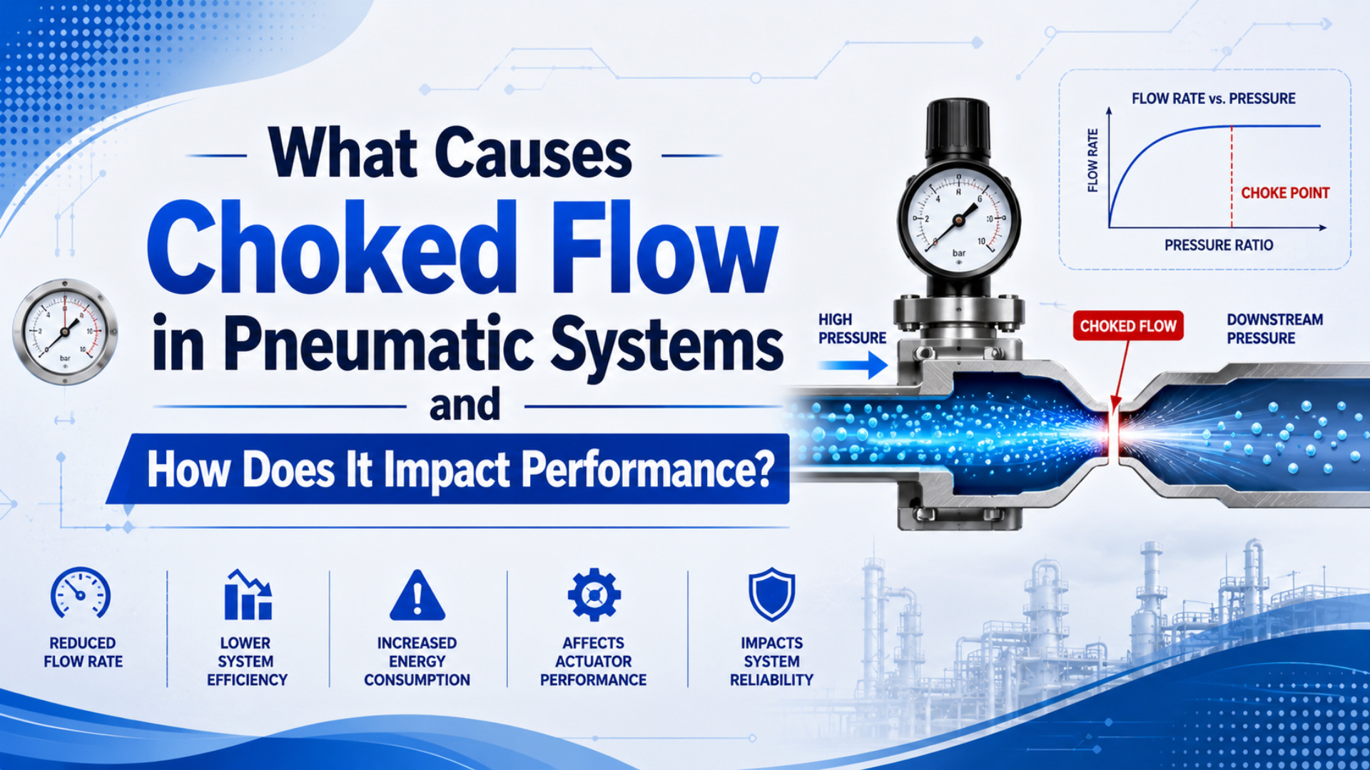
Choked flow is a sonic mass-flow ceiling inside a pneumatic restriction. It happens when compressed air reaches sonic velocity at the smallest effective passage, such as a valve land, muffler, fitting, or orifice. After that point, lowering downstream pressure does not create the expected extra mass flow.
The practical result is simple: a cylinder can have good static supply pressure and still move slowly during the part of the cycle that needs the most air. Choked flow is not the same as ordinary pressure drop, but it often appears beside pressure drop because both start with a restriction.
Key Takeaways
- For ideal air, choking starts near a downstream-to-upstream absolute pressure ratio of 0.528.
- NASA shows maximum mass flow occurs at Mach 1, so the smallest area controls the limit.
- Fix the restriction before raising compressor pressure; CAGI says 10% system pressure drop is the usual design ceiling.
The useful field question is not “Is the compressor big enough?” It is “Which part of this air path reaches its flow ceiling first while the actuator is moving?”
What Is Choked Flow in a Pneumatic System?
Choked flow is the maximum mass-flow condition through a restriction. NASA’s compressible-flow derivation shows that, for fixed area, total pressure, and total temperature, the mass-flow curve reaches its limiting maximum at Mach 1 (NASA Glenn Research Center, 2021).
In plant language, the smallest effective area becomes the throat. It might be a valve land, a push-in fitting, a speed controller, a clogged muffler, a quick disconnect, or a small drilled orifice. Once the air reaches sonic velocity at that point, more downstream demand cannot pull proportionally more air through the same opening.
That is why a slow actuator can look confusing. The upstream regulator may show enough pressure, the compressor may have spare capacity, and the cylinder may be mechanically healthy. The fault sits in the route between them.
Use the term carefully. Choked flow does not mean “all air stopped.” It means the restriction has reached a flow ceiling for the current upstream pressure, temperature, gas, and effective area.
What Pressure Ratio Causes Choked Flow?
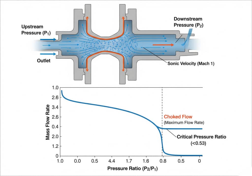
For ideal dry air with a heat-capacity ratio near 1.4, the critical downstream-to-upstream absolute pressure ratio is about 0.528. Parker’s pneumatic valve sizing note uses the same practical boundary by requiring outlet pressure P2 to stay above 0.53 x P1 for its subcritical air-flow calculation (Parker Hannifin, 2026).
Use absolute pressure, not gauge pressure, for this check. A 7 bar gauge supply is about 8 bar absolute near sea level. If the downstream side of a restriction falls below roughly 4.2 bar absolute, the flow path may be at or near the choked boundary.
Critical pressure ratio is the downstream absolute pressure divided by upstream absolute pressure at the onset of sonic limiting behavior. For air, the practical field value is about 0.53, which is why gauge readings must be converted before a serious choke check.
Pressure ratio = P2 absolute / P1 absolute

If the ratio is above 0.53: subcritical flow is more likely.
If the ratio is near 0.53: the restriction is at the critical boundary.
If the ratio is below 0.53: treat the restriction as a choked-flow suspect.
NIST lists 1 psi as 6,894.757 Pa and 1 atm as 101,325 Pa, which is a useful reminder that pneumatic pressure math depends on unit discipline (NIST, 2026). Do not mix psig, psia, bar gauge, and bar absolute in one calculation.
How Does Choked Flow Impact Pneumatic Performance?
Choked flow limits actuator speed because the air path cannot pass more mass flow through the same restriction. CAGI says most well-designed compressed-air systems stay within 10% pressure drop from compressor discharge to point of use, but a choked local restriction can waste that margin at one machine (CAGI, 2026).
The first symptom is usually a speed ceiling. You raise supply pressure, open a speed controller, or shorten the dwell, but the cylinder does not respond in proportion. The flow path has stopped behaving like a normal adjustable restriction.
The second symptom is direction-specific motion. One stroke may be fine while the other is slow because exhaust air must leave through a different valve path, muffler, tube, or meter-out control. A supply-side restriction can slow filling. An exhaust-side restriction can create back pressure.
For a rodless cylinder, the problem is more visible because long strokes move more air per cycle. A valve and tube set that works on a compact clamp can starve a long transfer axis when cycle time tightens.
Field Symptoms That Separate Choked Flow From Pressure Drop
Pressure drop increases with flow resistance, while choked flow is the point where the smallest effective area has reached sonic limiting behavior. ISO 6358-1 remains current after 2022 review and defines steady-state testing for pneumatic components using compressible fluids and internal flow paths (ISO, 2013).
Use pressure drop as the broader diagnostic frame and choked flow as the sharper suspect. The field test is still practical: measure before and after the suspected restriction while the machine runs at the failed cycle speed.
| Field observation | More likely ordinary pressure drop | More likely choked flow |
|---|---|---|
| Speed improves when pressure rises | Yes | Only a little, or only after upstream pressure changes enough |
| Downstream pressure keeps falling with demand | Yes | Falls near or below the critical pressure-ratio boundary |
| One valve path or muffler is loud | Possible | Strong suspect if it is also the narrowest path |
| Static gauge looks normal | Common | Common |
| Larger tube helps | Often | Helps only if tube or fitting was the actual throat |
In our experience, the most useful clue is a two-gauge test during motion. One gauge before the suspect part and one after it will show whether the fault is ordinary loss across a long path or a hard flow ceiling across one local restriction.
Do not diagnose from sound alone. Sonic hiss, high-pitched exhaust noise, and hot mufflers are useful clues, but pressure ratio and cycle behavior matter more.
Where Do Restrictions Usually Choke First?
The first choke point is usually the smallest effective passage under peak demand. CAGI recommends air velocity through piping at 20 ft/s or lower to reduce turbulence and pressure drop, which is a useful screening rule before blaming the cylinder (CAGI, 2026).
Check the parts that see peak flow first:
| Restriction point | Why it can become the throat | What to measure |
|---|---|---|
| Quick disconnect | small internal bore despite large outside size | pressure before and after the coupling |
| Flow control valve | needle setting or small passage dominates | stroke time and port pressure |
| Exhaust muffler | clogged element traps exhaust air | back pressure during return stroke |
| Manifold gallery | shared path feeds several valves | inlet pressure when simultaneous valves shift |
| Solenoid valve path | Cv differs by port and direction | supply path and exhaust path separately |
| Push-in fitting | tube OD hides smaller internal area | tube ID and fitting bore |
| Dirty FRL element | pressure drop rises over time | differential pressure across filter |
For tubing checks, separate tube outside diameter from inside diameter. A 10 mm OD tube is not a 10 mm flow passage. Wall thickness, fitting insertion depth, and branch length all change the real restriction.
Fix Order for Choked Flow Problems
Fix choked flow by increasing effective flow area, reducing avoidable restriction, or lowering peak demand. CAGI warns that raising compressor discharge pressure, raising local regulator settings, or adding another compressor are costly responses and should not be the first steps for pressure-drop problems (CAGI, 2026).
Use this order:
- Measure dynamic pressure before and after the suspected restriction.
- Convert both readings to absolute pressure for the pressure-ratio check.
- Remove clogged mufflers, loaded filters, blocked fittings, and damaged couplers.
- Increase tube ID or shorten tube length if the branch line is the throat.
- Check valve Cv, exhaust capacity, and manifold gallery size.
- Move the valve closer to the actuator if long tubing is unavoidable.
- Add local receiver volume only when the event is intermittent and measured demand supports it.
- Reset compressor pressure after the restriction is fixed.
The wrong fix is usually expensive because it treats symptoms upstream. More compressor pressure can hide a restriction, increase leak flow, and make exhaust noise worse without changing the narrowest effective passage.
For control circuits, compare this fix order with meter-in vs meter-out flow control. For valve capacity, use the dedicated flow coefficient Cv guide and the valve pressure-drop calculation guide.
What Should You Send for a Flow Review?
Send enough data to identify the throat. Parker’s example converts a 3-1/4 inch bore cylinder, 12 inch stroke, 1 second stroke time, and 80 psi supply into required Cv 1.06, showing why bore, stroke, pressure, and target time must be known before valve selection (Parker Hannifin, 2026).
A useful review package includes:
| Data item | Why it matters |
|---|---|
| Upstream pressure before the suspect part | sets P1 for the ratio check |
| Downstream pressure during motion | sets P2 and shows delivered pressure |
| Bore, stroke, and cycle time | defines actuator air demand |
| Valve model and Cv or rated flow | identifies supply and exhaust path limits |
| Tube OD, tube ID, and length | identifies line loss and volume |
| Fitting, quick disconnect, and muffler model | often hides the smallest bore |
| Load and required speed | separates force problems from flow problems |
| Photo or schematic of the air path | avoids guessing which component is upstream |
For broader system loss, use the pressure drop troubleshooting guide. For flow-to-pressure confusion, use the companion guide on converting air flow to pressure in pneumatic systems. If the circuit is solenoid-valve controlled, the pneumatic solenoid valve guide helps identify which port path is active.
When you send data for engineering review, include the actual fault condition. “Slow sometimes” is hard to size. “Extend stroke must finish in 0.8 seconds at 6 bar gauge with a 63 mm bore and 1.5 m tube run” is useful.
For project support, send the measurements through technical support. Keep the request technical: pressures, times, valve model, tube size, and photos of the suspected restriction.
FAQs About Choked Flow in Pneumatic Systems
FAQ answers should keep the same pressure-ratio boundary visible because the 0.528 to 0.53 range is the practical separator between ordinary subcritical gas flow and a choked-flow suspect for air (Parker Hannifin, 2026).
Is choked flow the same as pressure drop?
No. Pressure drop is any pressure loss while air flows through resistance. Choked flow is the limiting condition where the smallest effective restriction reaches sonic behavior and downstream pressure reduction no longer gives proportional flow increase. Pressure drop is the broad problem; choked flow is one specific high-ratio boundary inside it.
Can choked flow damage a pneumatic cylinder?
Choked flow usually hurts performance before it directly damages the cylinder. The real risk is indirect: slow motion, poor force margin, noisy exhaust, hotter local restrictions, unstable cycle timing, and operators raising supply pressure to compensate. Check the valve, muffler, tube, fitting, and regulator before replacing the actuator.
How do I calculate whether my pneumatic circuit is choked?
Measure upstream and downstream pressure across the suspected restriction while air is flowing. Convert both to absolute pressure, then calculate P2_abs / P1_abs. If the ratio is near or below 0.53 for air, the part is a choked-flow suspect. Use manufacturer flow data for final sizing.
Why does increasing pressure not make the cylinder faster?
If the smallest passage is choked, extra downstream demand cannot pull more air through that same opening. Upstream pressure can still affect mass flow, but the response will not match a normal pressure-drop correction. That is why a higher regulator setting may add noise and leakage without fixing cycle time.
Which component should I check first?
Check the part that sees the highest flow during the failed motion: valve path, muffler, quick disconnect, flow control, manifold gallery, local FRL, or tube run. Use two gauges. If one component consumes most of the dynamic pressure ratio, fix that restriction before changing the compressor or cylinder.
Sources and Retrieval Notes
Use these notes to preserve the FLOW evidence triple for future updates. Retrieval date: 2026-07-08.
- NASA Glenn Research Center: Mass Flow Choking, maximum mass flow occurs at Mach 1 for fixed area, total pressure, and total temperature. Retrieved 2026-07-08.
- NASA Glenn Research Center: Mach Number, Mach number is the ratio of object or flow speed to speed of sound. Retrieved 2026-07-08.
- Parker Hannifin: Pneumatic Products Catalog 0600P-E Introduction, valve Cv sizing example and subcritical air-flow boundary using
P2 > 0.53 x P1. Retrieved 2026-07-08. - CAGI: Pressure Drop Technical Brief, 10% pressure-drop guidance, 20 ft/s velocity guidance, and warning against first-response pressure increases. Retrieved 2026-07-08.
- ISO 6358-1:2013, pneumatic component flow-rate testing with compressible fluids, confirmed current in 2022. Retrieved 2026-07-08.
- NIST: Pressure and Gas Flow Unit Conversions, pressure and gas-flow conversion table including 1 psi = 6,894.757 Pa. Retrieved 2026-07-08.