

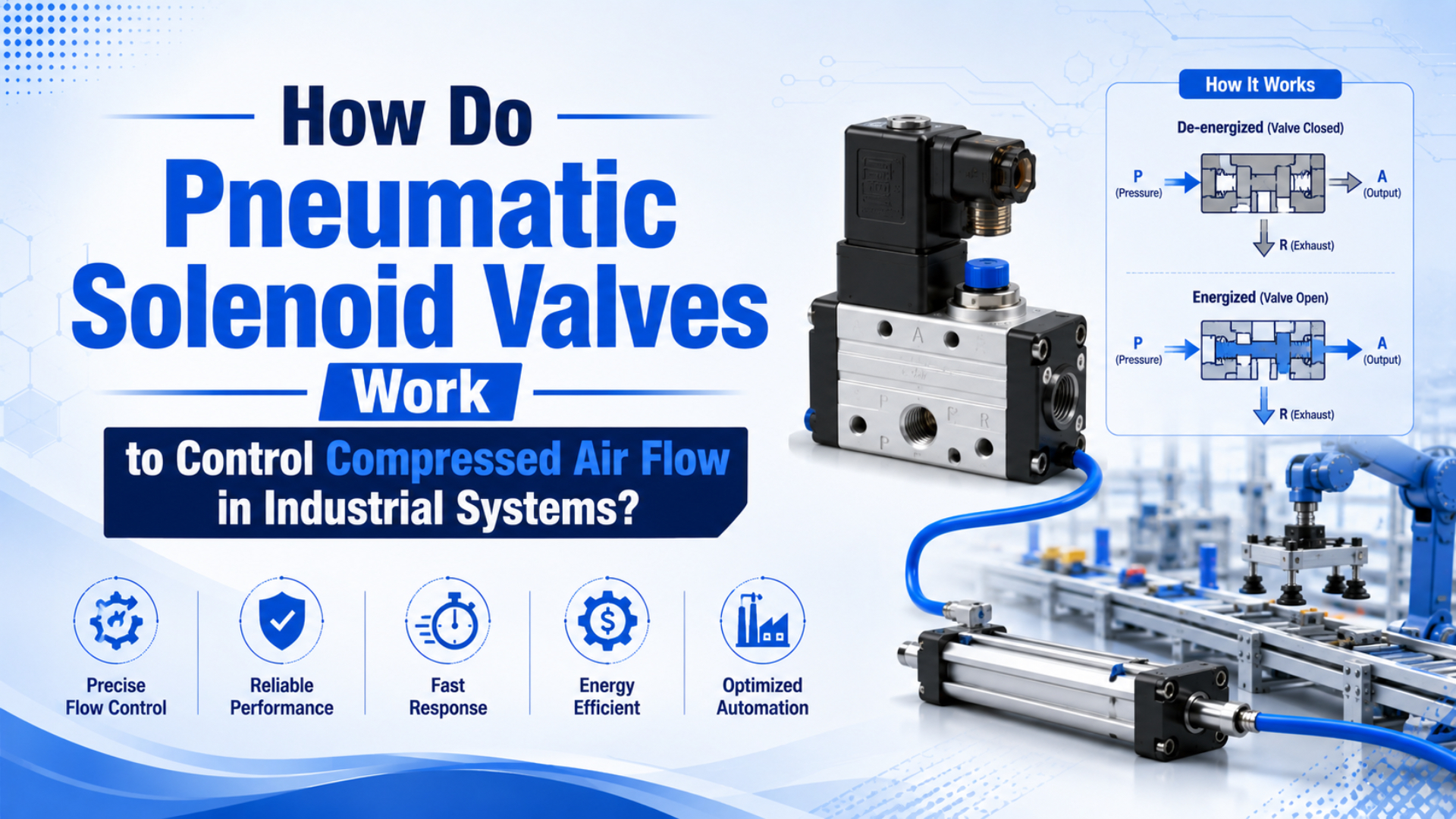
Pneumatic solenoid valve is an electrically actuated air valve that changes compressed-air paths when its coil receives a control signal. When a PLC output, relay, or manual switch energizes the coil, the magnetic field moves a plunger or pilot element. The valve then connects pressure, actuator, and exhaust ports so a cylinder, gripper, or air circuit changes state.
That is the short answer. However, the useful engineering answer is narrower: the coil starts the command, but the port function, pilot pressure, Cv, exhaust path, air quality, and wiring decide whether the actuator actually moves on time.
Key Takeaways
- Tameson describes a solenoid valve as 2 main parts: a solenoid and a valve body.
- CAGI says well-designed compressed-air systems usually stay within 10% pressure drop from compressor discharge to point of use.
- Size the valve from actuator demand first, then confirm coil voltage, port function, Cv, exhaust, and air quality.
In our experience, most solenoid-valve problems are not “bad valve” problems at first. The coil light turns on, so everyone looks downstream. Then the real cause turns out to be a 24 VDC coil supplied by the wrong module, a blocked muffler, a 5/2 valve used where a 5/3 center condition was needed, or point-of-use pressure that collapses during the stroke.
Use valve function, supply pressure, exhaust capacity, manifold sizing, and fault behavior together when reviewing directional-valve performance.
How does a pneumatic solenoid valve convert electricity into air flow?
A pneumatic solenoid valve converts electricity into air routing by using a coil to move a plunger, armature, poppet, or pilot stage. Tameson describes 2 core parts, the solenoid and the valve body, and Parker shows solenoid-operated valves across 3-, 4-, and 5-port layouts (Tameson, 2024; Parker, 2026).
The sequence is simple enough to remember:
- The controller sends voltage to the coil.
- Current through the coil creates a magnetic field.
- The magnetic force moves the plunger or pilot element.
- The valve changes which ports are connected.
- Compressed air enters one circuit path while another path closes or exhausts.
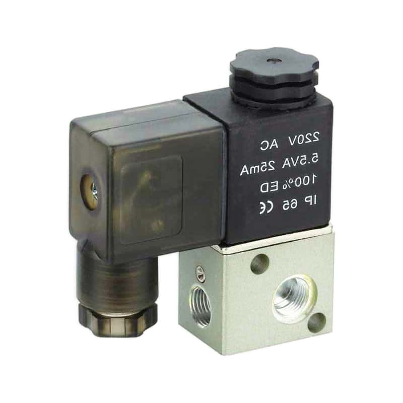
For a simple 2/2 valve, that may only mean open or closed. For a 3/2 valve, pressure may connect to the actuator port while the exhaust port closes. For a 5/2 valve, one cylinder port gets pressure while the other exhausts. Therefore, “the solenoid valve works” is not a complete diagnosis. Which port changed state?
We normally separate the electrical and pneumatic questions during review. First, did the coil receive the right voltage and polarity? Second, did the spool or poppet shift? Third, did the actuator receive enough pressure and flow while the opposite chamber exhausted? Skipping that order wastes time.
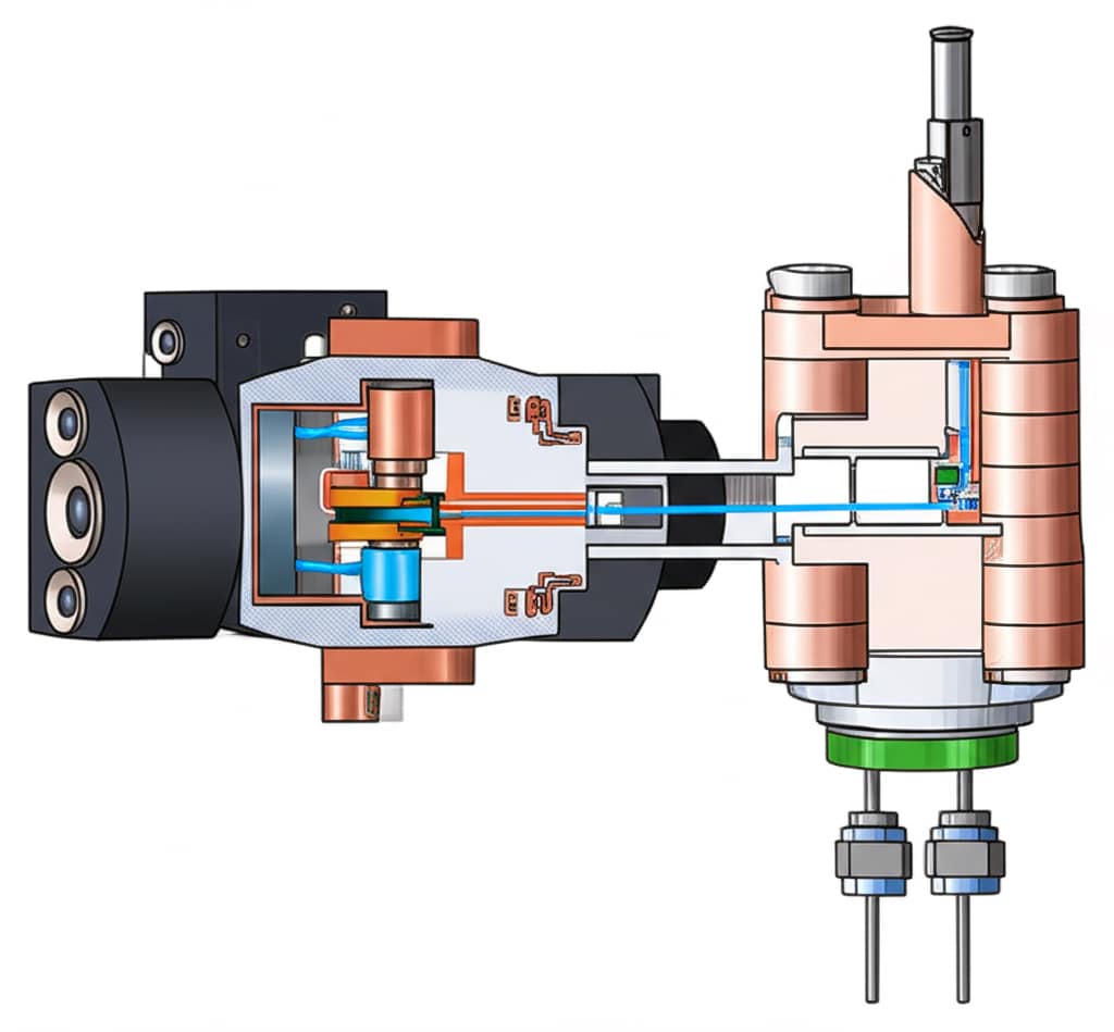
| Part | What it does | Failure symptom |
|---|---|---|
| Coil | creates magnetic force | no click, hot coil, weak shift |
| Plunger or armature | starts the mechanical movement | buzzing, sticking, delayed opening |
| Spool or poppet | changes air passages | wrong port pressurized, internal leakage |
| Spring return | sets the de-energized position | valve stays shifted or returns slowly |
| Exhaust port | vents the actuator side | slow retract, back pressure, noise change |
If you need the deeper pilot-stage explanation, use the related guide on pneumatic pilot operated valves. This article stays focused on solenoid-commanded valve selection and troubleshooting.
Valve configuration choices: 2/2, 3/2, 5/2, and 5/3
Valve configuration decides what the electrical command can do to the air circuit. Tameson’s 5/2 pneumatic solenoid example lists 1 inlet port, 2 exhaust ports, and 2 outlet ports, while its 3/2 example uses 3 ports and 2 positions (Tameson, 2024).
First, a 2/2 valve has 2 ports and 2 positions. Use it for on/off flow, blow-off, simple air supply isolation, or vacuum switching where the circuit only needs open and closed states.
Next, a 3/2 valve has pressure, actuator, and exhaust paths. It is the common choice for single-acting cylinders, pilot signals, air release, or small pneumatic logic tasks. The 3V1 3/2 solenoid valve product family belongs in this kind of compact control conversation.
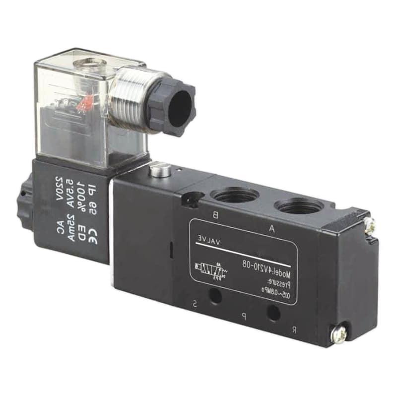
Then, a 5/2 valve has one pressure port, two working ports, and two exhaust ports. It is a normal choice for double-acting cylinders and many rodless cylinder axes. Need the port-routing background? Read the 4-way 5-port pneumatic valve guide.
Finally, a 5/3 valve adds a center position. That center state can block ports, exhaust ports, or pressurize both sides depending on the design. Choose it only after deciding what the load should do during power loss, E-stop, pause, or manual intervention.
Direct-acting vs pilot-operated solenoid valves
Direct-acting and pilot-operated solenoid valves solve different flow problems. Tameson says direct-acting valves operate without differential pressure. By contrast, indirect or pilot-operated valves require about 0.5 bar pressure differential and use that pressure to help control larger flow (Tameson, 2024).
Direct-acting valves let the coil move the sealing element directly. They are simple, compact, and useful when the circuit has low flow, low pressure differential, or a need to work from zero pressure. The tradeoff is force. A small coil can only move a limited orifice or sealing area.
Pilot-operated valves use a small pilot action to move a larger main stage. That can provide more capacity for cylinder circuits, manifolds, and machine stations, but it brings another condition: the pilot stage needs enough pressure and clean passages to shift reliably.
Semi-direct valves sit between those two categories. They can work from zero pressure in many designs while still using pressure assistance for larger flow. Do not assume the name alone proves the behavior. Check the datasheet.
| Selection point | Direct-acting | Pilot-operated | Semi-direct |
|---|---|---|---|
| Minimum pressure | often works from zero | needs rated pilot or differential pressure | often works from zero |
| Flow capacity | lower | higher | medium to high |
| Coil force demand | higher per orifice size | lower because air assists the main shift | higher than indirect in many designs |
| Best use | small flow, pilot signals, low-pressure circuits | larger cylinders, manifolds, high flow | mixed low-pressure and higher-flow cases |
What does this mean on a real machine? If the valve clicks but the cylinder barely moves, the coil may not be the limiting part. Check whether the valve type needs minimum pressure, whether the exhaust path is blocked, and whether the main spool can pass the required flow.
How do you size a solenoid valve for compressed air flow and cylinder speed?
Size a pneumatic solenoid valve from required actuator flow, not from thread size alone. SMC gives s = 28.8q / A, where speed depends on airflow and piston area. Meanwhile, Parker’s selector lists valve flow ratings from Cv 0.01 to 29.9 (SMC, 2026; Parker, 2026).
Start with the actuator motion. Bore, stroke, working pressure, load, tube length, and desired stroke time define the air demand. Then check the valve, fittings, tube ID, speed controller, manifold, and muffler as one flow path.
However, do not buy by port thread only. A 1/4 inch valve may have very different internal flow capacity from another 1/4 inch valve. The same is true for manifolds: the individual station may look acceptable while the shared supply gallery is too small for simultaneous operation.
Use this order for solenoid valve sizing:
- Define actuator type: single-acting, double-acting, rodless cylinder, gripper, blow-off, or pilot circuit.
- Define movement: extend time, retract time, load direction, and required repeatability.
- Estimate flow demand from bore, stroke, pressure, and stroke time.
- Compare candidate valve Cv or flow rating against that demand.
- Check both supply and exhaust paths, including mufflers and meter-out controls.
- Confirm the valve’s pressure range, minimum pilot requirement, and coil voltage.
- Test point-of-use pressure while the actuator moves, not only while idle.
For a deeper calculation article, use the dedicated guide on flow coefficient Cv. For speed-control method choice, connect this valve selection to the meter-in vs meter-out guide.
Which electrical and environmental checks prevent nuisance failures?
Nuisance solenoid-valve faults usually come from voltage, heat, contamination, or pressure drop rather than from the valve nameplate alone. ISO 8573-1:2010 specifies compressed-air purity classes for particles, water, and oil, and ISO says the 2010 edition remains current after its 2017 confirmation (ISO, 2010).
First, electrical checks start with coil voltage. Match AC or DC, voltage rating, duty cycle, connector type, surge suppression, and PLC output capacity. A 24 VDC coil on the wrong supply may click weakly, overheat, or chatter under load. Also check manual override position. It sounds basic because it is basic.
Second, air-quality checks matter because the valve has tight moving clearances. Water, oil aerosol, pipe scale, thread sealant, and dust can make a spool stick or a plunger drag. Place the FRL unit where it protects the valve manifold, not only where it looks neat in the cabinet.
Finally, environmental checks include temperature, washdown exposure, dust, vibration, cable strain, and exhaust placement. The coil may be rated for one enclosure condition while the connector, cable gland, or field wiring creates the weak point. If the station sits near water, coolant, flour dust, metal chips, or outdoor weather, confirm the full assembled protection level.
One practical rule: never diagnose a valve with only the cabinet open. Watch the valve while the machine cycles. Listen to the exhaust. Feel for coil heat after several minutes. Measure pressure at the valve inlet during motion. Those four checks catch many faults before parts are replaced.
How should maintenance teams troubleshoot slow or erratic solenoid-valve motion?
Troubleshoot from command to air delivery. CAGI states that well-designed systems usually have no more than 10% pressure drop between compressor discharge and any point of use, and warns that raising compressor discharge pressure should not be the first response to low point-of-use pressure (CAGI, 2022).
First, start with the electrical signal. Verify voltage at the coil during the actual command, not only at the terminal block with the load disconnected. If the coil has an LED, treat it as a clue, not proof. An LED can be on while the voltage is low, the common is wrong, or the coil is mechanically jammed.
Next, isolate the pneumatic path. Does the manual override move the actuator? Does the exhaust port blow strongly? Does removing the muffler temporarily change speed? Does the pressure gauge dip during motion? A slow cylinder often points to flow restriction, blocked exhaust, low supply, swollen seals, or wrong speed-control adjustment.
| Symptom | Likely checks | What not to assume |
|---|---|---|
| Coil hot | wrong voltage, duty cycle, ambient heat, blocked plunger | heat alone proves the valve body is bad |
| Valve clicks but no motion | low supply, wrong porting, blocked exhaust, actuator jam | the electrical command is enough |
| Motion slow in one direction | meter-out setting, muffler, tube kink, load direction | both directions have equal flow |
| Chatter or buzz | low voltage, AC shading issue, contamination, unstable pressure | the coil is the only cause |
| Random sticking | water, oil, dirt, seal swell, old lubricant | replacement fixes the air-quality problem |
If the application uses rodless cylinders or long-stroke cylinders, also check tubing volume and exhaust routing. Long air paths add delay. Small silencers add back pressure. A solenoid valve can be electrically correct and pneumatically too restrictive.
RFQ checklist for pneumatic solenoid valve replacement
A good replacement request identifies function, flow, pressure, voltage, and environment before price. Parker’s selector spans 2-, 3-, and 4-way valves, 2- and 3-position options, and Cv values from 0.01 to 29.9. Therefore, a photo alone is not enough for matching (Parker, 2026).
Send these details before asking for a direct replacement:
| RFQ item | Why it matters |
|---|---|
| Valve function | 2/2, 3/2, 5/2, 5/3, center condition, spring return, double solenoid |
| Port size and thread | G, NPT, PT, metric fittings, manifold interface |
| Flow rating | Cv, Kv, NL/min, SCFM, or catalog series reference |
| Pressure range | working pressure, minimum pilot pressure, vacuum use, pressure spikes |
| Coil data | voltage, AC or DC, wattage, connector type, surge suppression |
| Environment | temperature, washdown, dust, vibration, outdoor exposure |
| Actuator demand | bore, stroke, target cycle time, load, simultaneous valve count |
| Current symptoms | slow shift, coil heat, leakage, sticking, repeated burnout |
For standard product context, start with pneumatic solenoid valves and the 200 Series directional control valve family. For engineering review or unclear replacements, send the checklist through contact with photos of the valve label, manifold, wiring connector, exhaust ports, and actuator.
The final check is compatibility under motion. A replacement can match the thread, voltage, and mounting pattern but still fail the cycle if Cv, exhaust capacity, or minimum pilot pressure is different. That is the point where a cheap replacement becomes expensive.
Conclusion
Pneumatic solenoid valves control compressed air by using electrical force to change valve position. The coil starts the action. The port function, spool or poppet design, pilot pressure, Cv, exhaust path, air quality, and wiring decide the result.
If the actuator is slow, erratic, or unreliable, do not start with a part swap. Start with the circuit: command, coil, shift, supply pressure, exhaust, actuator load, and air quality. That order gives maintenance teams a faster path to the real cause.
FAQs About Pneumatic Solenoid Valves
What is a pneumatic solenoid valve?
A pneumatic solenoid valve is an electrically actuated valve that controls compressed-air paths. It uses a coil and moving plunger, poppet, spool, or pilot stage to connect or block pressure, actuator, and exhaust ports. The valve may be 2/2, 3/2, 5/2, 5/3, direct-acting, pilot-operated, or semi-direct depending on the circuit.
What is the difference between a 3/2 and 5/2 solenoid valve?
A 3/2 valve has 3 ports and 2 positions, usually pressure, actuator, and exhaust. It commonly controls single-acting cylinders or pilot signals. A 5/2 valve has 5 ports and 2 positions, commonly pressure, 2 actuator ports, and 2 exhaust ports for a double-acting cylinder.
Why does my solenoid valve click but the cylinder does not move?
A click means the coil or plunger may be moving, but it does not prove the actuator is receiving useful flow. Check supply pressure during motion, port connections, manual override state, blocked mufflers, meter-out valves, pilot pressure, actuator load, and whether the selected valve function matches the cylinder.
Do pneumatic solenoid valves need clean air?
Yes. ISO 8573-1 defines compressed-air purity classes for particles, water, and oil. In practice, dirt, water, oil aerosol, old pipe scale, and thread sealant can make small plungers and spools stick. Place filtration and regulation close enough to protect the valve manifold and downstream actuator.
How do I choose the right solenoid valve size?
Start with actuator demand: bore, stroke, working pressure, desired stroke time, load, and simultaneous valve count. Then compare valve Cv or flow rating, port size, tube ID, manifold capacity, mufflers, and pressure drop. SMC’s speed formula ties cylinder speed to airflow and piston area, so valve sizing must follow the motion requirement.
Should I use direct-acting or pilot-operated solenoid valves?
Use direct-acting valves for small flow, pilot signals, and cases where operation from zero pressure is required. Use pilot-operated valves when the circuit needs larger main flow and has enough rated pilot or differential pressure. Use the datasheet, not the category name alone, to confirm minimum pressure and capacity.
Sources
- Tameson: Solenoid Valve Types, direct-acting, indirect, semi-direct, normally open, normally closed, and 0.5 bar differential-pressure guidance. Retrieved 2026-07-08.
- Tameson: Directional Control Valves in Pneumatic Systems, 5/2 and 3/2 pneumatic solenoid valve connection examples. Retrieved 2026-07-08.
- Parker: Pneumatic Products Catalog 0600P-E, valve selector chart by flow, port count, operators, pressure range, and Cv. Retrieved 2026-07-08.
- SMC: Control Air Flow of Cylinders, cylinder speed formula and exhaust-side flow-control note. Retrieved 2026-07-08.
- CAGI: Pressure Drop Technical Brief, 10% pressure-drop guideline and first-response troubleshooting advice. Retrieved 2026-07-08.
- ISO 8573-1:2010, compressed-air purity classes for particles, water, and oil, current after 2017 confirmation. Retrieved 2026-07-08.
- AutomationDirect: Understanding Pneumatic Valve Ports and Ways, video reference for valve port and way naming. Retrieved 2026-07-08.