

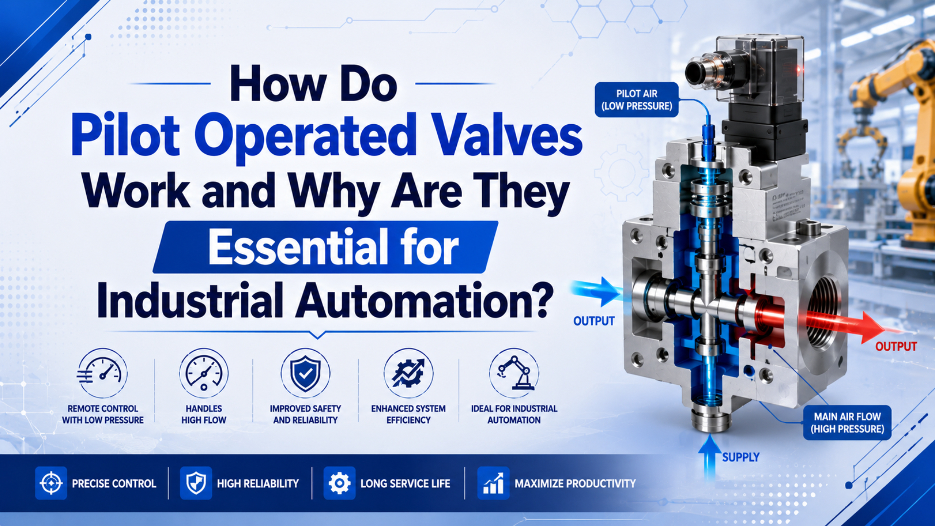
Pilot operated valves work by using a small pilot stage to control a larger main valve element. The pilot stage shifts pressure in a control chamber or spool end, and that pressure differential moves the main diaphragm, piston, poppet, or spool. This lets a compact solenoid or air signal control a higher-flow process or pneumatic circuit.
That does not mean every pilot valve is the same. A 2/2 diaphragm solenoid valve for water, air, or neutral fluids is not the same product as a 5/2 pneumatic directional valve driving a cylinder. The shared idea is two-stage control. The selection checks are different.
Key Takeaways
- Tameson notes that indirect, pilot-operated solenoid valves usually need about 0.5 bar differential pressure, so zero-pressure service needs a direct or assisted-lift design.
- CAGI recommends no more than 10% pressure drop from compressor discharge to point of use.
- Size the main valve path, pilot supply, tubing, and exhaust together.
In our experience, many pilot-valve failures are not coil failures. The coil energizes, the LED turns on, and the machine still moves slowly. Why? The pilot path may be dirty, the pilot supply may collapse during motion, or the exhaust muffler may be choking the main valve.
What Is a Pilot Operated Valve?
A pilot operated valve is a 2-stage valve: a small pilot device controls a larger main flow path. Tameson separates solenoid valves into direct, indirect, and semi-direct types, and states that indirect-acting valves require about 0.5 bar pressure differential to operate (Tameson, 2024).
The pilot stage may be an electrical solenoid, an air pilot, a hydraulic pilot, or a small manual operator. Its job is not to carry the full process flow. It only changes pressure on the control side of the main valve.
The main stage does the real flow work. In a process valve, that may be a diaphragm, piston, or poppet. In a pneumatic directional valve, it is usually a spool that connects pressure, actuator, and exhaust ports.
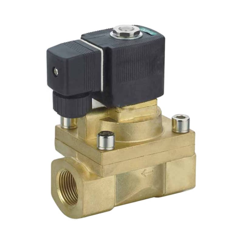
That distinction keeps the article from becoming too broad. A pilot operated valve can control compressed air, water, neutral gas, coolant, steam-rated media, or a pneumatic cylinder circuit, but the datasheet must match the medium and function.
| Pilot operated valve family | Main element | Common automation role | Main selection risk |
|---|---|---|---|
| Indirect diaphragm solenoid valve | diaphragm | 2/2 on-off media control | minimum differential pressure |
| Semi-direct solenoid valve | assisted diaphragm | low or zero-pressure on-off control | larger coil and heat |
| Pneumatic directional valve | spool | cylinder extend, retract, hold, exhaust | Cv, exhaust, pilot supply |
| Pneumatic angle seat valve | piston-actuated seat | high-cycle process flow | actuator air pressure and seal material |
Use the word “pilot” carefully in RFQs. It describes the actuation principle, not the port count, medium, seal material, voltage, or flow rating.
A pilot operated valve is best understood as a control amplifier: the pilot stage handles the small command, and the main stage handles the useful flow. For indirect diaphragm valves, the amplifier depends on pressure differential; Tameson gives about 0.5 bar as the required differential for indirect-acting solenoid valves (Tameson, 2024). For pneumatic directional valves, the same idea shifts into a spool body that routes pressure and exhaust to actuator ports. That shared two-stage logic is why pilot operation appears in process valves, cylinder valves, manifolds, and remote-control circuits. The selection risk is also shared: if pilot pressure, bleed passages, or main flow paths are not checked, the valve may receive the command and still fail to move the load correctly.
How Does the Two-Stage Operation Actually Work?
The two-stage cycle starts when the pilot path changes pressure on one side of the main element. Tameson describes a solenoid valve as a valve body plus solenoid, and an indirect valve as one that uses pressure difference to amplify a small solenoid action into higher flow (Tameson, 2024).
In a normally closed diaphragm-style valve, the closed state usually keeps pressure above the diaphragm. The inlet pressure and spring help hold the main seat shut. A small bleed path lets pressure equalize in the control chamber.
When the coil energizes, the pilot orifice opens. Pressure above the diaphragm drops. Inlet pressure below the diaphragm then lifts the diaphragm and opens the main flow path. The solenoid moved only a small pilot orifice, not the full valve seat.
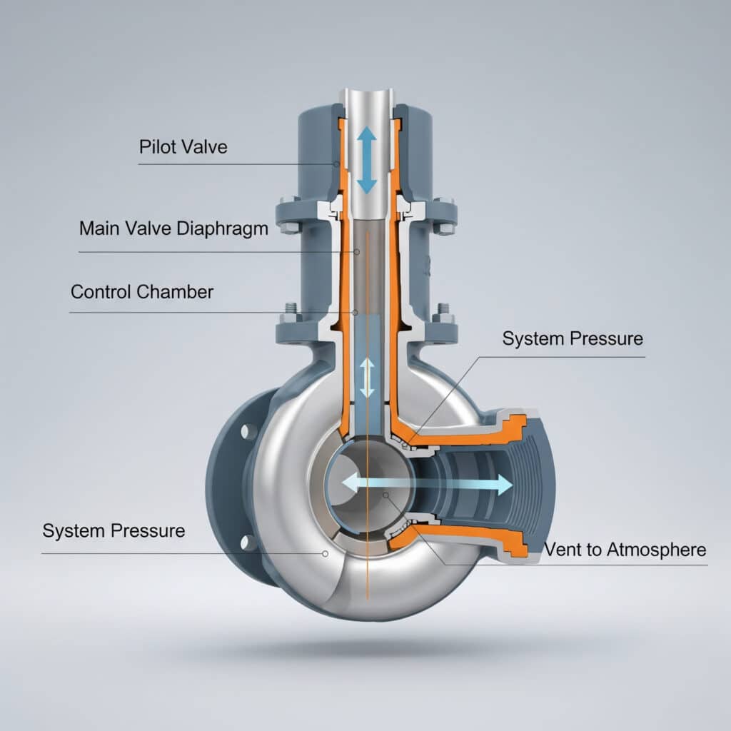
For a spool-type pneumatic valve, the principle changes shape but not logic. A pilot signal pressurizes one end of the spool and vents the other. The spool shifts, connecting supply air to one actuator port while the other port exhausts.
That is why a pilot operated valve should be checked as two circuits:
- The pilot circuit: command, coil voltage, pilot pressure, pilot exhaust, bleed path.
- The main circuit: valve Cv, pressure drop, tube ID, muffler restriction, actuator volume.
If either circuit fails, the machine fails. A clean PLC output cannot overcome a blocked pilot exhaust, and a strong pilot signal cannot make an undersized main valve pass enough flow.
What Makes Pilot Operation Different from Direct Acting Control?
Direct acting valves move the sealing element directly, while pilot operated valves use pressure differential to move the larger element. Tameson says direct-acting solenoid valves operate without differential pressure, while indirect-acting valves require about 0.5 bar and are used where sufficient differential pressure and higher flow are available (Tameson, 2024).
That tradeoff is the heart of the selection. Direct acting is better when the circuit may start from zero pressure, the orifice is small, or the response must be very immediate. It is mechanically simple. It can also need a stronger actuator for larger orifices.
Pilot operation fits larger flow paths. The pilot device can stay compact because system pressure or pilot pressure does the heavy lifting. But the design needs enough pressure differential, clean pilot passages, and the correct flow direction unless the valve is designed for bidirectional service.
| Selection factor | Direct acting valve | Pilot operated valve |
|---|---|---|
| Low or zero pressure | usually stronger fit | depends on design |
| Large flow path | coil or operator grows quickly | main stage handles flow |
| Dirt sensitivity | simpler path | pilot orifice can clog |
| Response feel | fast and direct | slightly delayed by pilot volume |
| Common use | small air signals, low-flow media, safety vents | process on-off flow, larger cylinders, valve manifolds |
So, which one should you choose? Start with the failure mode. If the machine must open at zero pressure, do not choose a standard indirect pilot valve. If the machine needs high flow from a compact control signal, pilot operation usually deserves the first review.
Where Do Pilot Operated Valves Fit in Industrial Automation?
Pilot operated valves fit where a small command must switch a larger flow path. CAGI lists control applications as air or gas used to trigger, start, stop, modulate, or direct machines and processes, including pneumatic machines and explosion-proof requirements (CAGI, 2026).
In process automation, a pilot operated solenoid valve may control water, compressed air, neutral gas, coolant, or steam-rated service. In pneumatic automation, a solenoid-pilot directional valve may control a clamp, press, diverter, pick-and-place axis, or rodless cylinder.
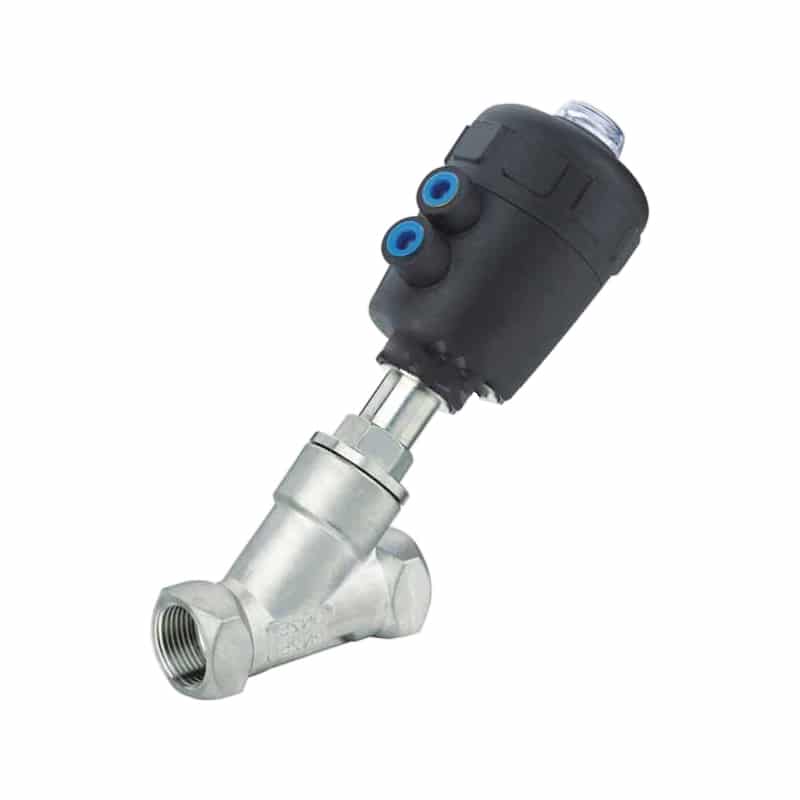
The essential benefit is separation of roles. The PLC, button, or pneumatic logic circuit handles the command. The main valve body handles the flow. That separation is valuable when the main valve is too large, too remote, too hot, or too demanding for direct electrical actuation.
Common industrial automation uses include:
- Process-fluid on-off control for air, water, coolant, and neutral media.
- Cylinder direction control in fixtures, packaging machines, and transfer equipment.
- Compressor unloading and blowdown circuits.
- Dust-collector pulse valves and cleaning circuits.
- Remote pneumatic control where electrical devices are limited by environment.
- Valve manifolds where compact electrical outputs control several high-flow stations.
Do not stretch the term too far. A valve can be pilot operated and still be wrong for a medium, pressure range, seal compatibility, duty cycle, or fail-safe state.
When Should You Choose Internal Pilot, External Pilot, or Direct Operation?
Choose internal pilot only when the main supply reliably stays inside the valve’s pilot-pressure range. CAGI states that every 2 psig of excess operating pressure can increase compressor power consumption by about 1%, so solving weak pilot shifting by raising plant pressure is usually the wrong first move (CAGI, 2026).
Internal pilot takes pilot air from the main supply port. It saves tubing and keeps the valve compact. It works well when supply pressure is stable and the main pressure does not sag below the valve’s required pilot range during motion.
External pilot uses a separate pilot feed. It helps when the main circuit runs at low pressure, sees fast pressure drop, or must use vacuum, pressure centers, or special center states. It also lets the pilot circuit receive cleaner or regulated air than the main flow path.
Direct operation is still the right answer when differential pressure is unavailable or unsafe to depend on. For example, a drain, vent, purge, or low-pressure fill circuit may need a direct or semi-direct valve.
| Condition | Best first choice | Reason |
|---|---|---|
| Main line always above pilot minimum | internal pilot | compact and simple |
| Main line dips during fast cylinder motion | external pilot | stable control supply |
| Startup from zero pressure | direct or semi-direct | no pilot differential needed |
| Dirty medium or particles | direct, isolated pilot, or filtered pilot | protects small pilot passages |
| Large cylinder with PLC output | solenoid-pilot directional valve | small signal controls larger main spool |
Measure dynamic pressure before choosing. Static pressure at rest can look fine, then collapse during the fastest stroke. A gauge at the valve inlet and pilot port tells a more honest story.
How Should You Size Flow, Cv, and Pressure Drop?
Size pilot operated valves from required flow, not from thread size. SMC gives the pneumatic cylinder speed relation s = 28.8q / A, where speed depends on airflow in SCFM and piston area in square inches with inlet pressure held constant (SMC, 2026).
That formula explains a common trap. A valve can have the same port thread as the old part and still be too restrictive for the cylinder volume or process flow. Cv, tubing ID, fittings, mufflers, and manifold passages all affect delivered flow.
For process valves, compare Cv or Kv against the actual pressure drop allowed by the process. For pneumatic directional valves, compare rated flow against the actuator’s worst direction, including the exhaust side. On a double-acting cylinder, retract and extend can have different air demands because the rod reduces effective area on one side.
Use this sizing order:
- Define process flow or actuator stroke-time demand.
- Convert units before comparing catalogs.
- Check valve Cv, Kv, or rated flow at the expected pressure drop.
- Check tube ID, tube length, fittings, manifold passages, and mufflers.
- Verify pilot pressure during motion, not only at rest.
- Test at the lowest expected supply pressure.
For a deeper pneumatic-only sizing workflow, see what is flow coefficient Cv and what causes pressure drop in pneumatic systems.
What Air Quality and Installation Details Protect Pilot Valves?
Pilot operated valves need clean pilot passages and stable pressure. ISO 8573-1:2010 specifies compressed-air purity classes for particles, water, and oil, and also identifies gaseous and microbiological contaminants in compressed-air systems (ISO, 2010).
Small pilot orifices are not forgiving. Particles can block the bleed path. Water can cause sticking or corrosion. Oil carryover can form varnish in tight passages. That is why a pilot valve can fail before a larger, direct-acting valve in the same plant air.
CAGI’s pressure-drop technical brief also warns that dirty filters create restriction and says filter elements should be changed when differential pressure exceeds 5-7 psig or at least every 6 months (CAGI, 2022).
Installation checks should include:
- Confirm the valve’s flow direction, especially on diaphragm solenoid valves.
- Match seal material to medium, temperature, oil exposure, and cleaning chemicals.
- Keep pilot exhaust open and protected from clogging.
- Mount mufflers where maintenance can reach them.
- Keep external pilot lines short and protected from heat or moving machine parts.
- Confirm manual override behavior before releasing the machine.
- Avoid using plant-pressure increases to hide a bad distribution or filter problem.
Need the air-preparation background? Read the guide on ISO compressed-air quality standards and the overview of FRL air source treatment units.
How Do You Troubleshoot a Pilot Operated Valve That Will Not Shift?
Troubleshooting should follow command, pilot, main supply, exhaust, and load. CAGI states that pressure drop comes from friction and resistance in piping, fittings, filters, dryers, and other components, so low point-of-use pressure should not be solved first by raising compressor discharge (CAGI, 2022).
Start with the command. Does the coil energize? Is the connector wired correctly? Does the manual override shift the valve? If manual override works but the electrical command does not, the problem is probably voltage, wiring, PLC output, connector, or coil.
Next, measure pilot pressure during the event. Do not trust static pressure. A pilot line can show enough pressure at rest and then collapse while a large actuator moves. If external pilot is available, feed it from a clean, stable regulated line and test again.
Then check the main air and exhaust paths. A clogged muffler can make a good valve look weak. A meter-out control can be too small. A manifold can restrict all stations. A cylinder seal can drag and be mistaken for valve trouble.
| Symptom | Likely area | First practical check |
|---|---|---|
| Coil on, no main movement | pilot or manual override | pilot pressure and pilot exhaust |
| Valve shifts by override only | electrical command | connector, voltage, PLC output |
| Chatter or half shift | pilot pressure below rating | dynamic pressure at pilot port |
| Slow cylinder both ways | supply or main valve flow | Cv, manifold, tube ID, filter drop |
| Slow one direction | exhaust or actuator side | muffler, meter-out valve, bent tube |
| Random sticking | contamination or seals | air quality, oil, debris, spool wear |
The fastest field check is usually simple: energize the command, watch pilot pressure, and listen to exhaust. If the pilot pressure is steady and the exhaust is silent or weak, the fault has moved away from the coil and toward the main path.
For speed-control tuning after the valve shifts correctly, use the guide on meter-in vs meter-out flow control.
What Should You Include in an RFQ for Pilot Operated Valves?
A useful RFQ should define demand, pressure, air quality, and fail-safe state. CAGI names demand, pressure, and air quality as central compressed-air selection requirements, and DOE lists compressed-air tools, tip sheets, and publications for improving performance and saving energy (CAGI, 2026; DOE, 2026).
Send the application, not only a part photo. A supplier can match thread size and voltage while missing the required differential pressure, seal material, flow coefficient, or pilot supply. That is how “drop-in replacements” become commissioning problems.
Include these details:
- Valve function: 2/2, 3/2, 4/2, 5/2, 5/3, normally closed, normally open, or center state.
- Medium: compressed air, neutral gas, water, coolant, steam, oil, or other fluid.
- Pressure range: minimum, normal, maximum, and pressure differential across the valve.
- Actuation: solenoid pilot, air pilot, external pilot, internal pilot, manual override.
- Electrical data: voltage, AC/DC, connector, duty cycle, protection requirement.
- Flow requirement: Cv, Kv, rated flow, or actuator stroke-time target.
- Air quality: filtration, dryer type, oil policy, ISO 8573-1 class if specified.
- Environment: temperature, washdown, dust, vibration, panel location, hazardous-area constraint.
- Fail-safe state: what the valve must do when power or pilot pressure is lost.
For international catalog comparison, convert units before quoting. Mixed psi, bar, MPa, Cv, Kv, SCFM, and L/min values can hide a sizing mismatch.
Selection Summary for Industrial Automation
Pilot operated valves are essential when small control energy must manage larger flow energy, but they are not universal replacements. Tameson lists direct, indirect, and semi-direct solenoid valve types, while CAGI’s 10% pressure-drop rule keeps the compressed-air side grounded in measured system performance (Tameson, 2024; CAGI, 2026).
Choose pilot operation when the machine has enough pressure differential or a stable external pilot supply, and when the main flow path is too large for direct operation to make sense. Choose direct or semi-direct operation when the circuit starts from zero pressure or the valve must open without help from system pressure.
For pneumatic cylinders, check Cv, tube ID, mufflers, pilot pressure, and actuator volume as one chain. For process-fluid valves, check pressure differential, flow direction, seal material, temperature, and medium compatibility. The same word, “pilot”, covers both worlds. The datasheet decides the safe answer.
For pneumatic automation, the sizing decision should connect cylinder flow demand with system pressure behavior. SMC’s cylinder-speed relation, s = 28.8q / A, ties actuator speed to airflow and piston area when inlet pressure is held constant (SMC, 2026). CAGI’s pressure-drop guidance then adds the plant-level limit: most well-designed compressed-air systems should stay within 10% pressure drop from compressor discharge to any point of use (CAGI, 2026). Together, those two references explain why valve Cv alone is not enough. A good pilot valve can underperform if the branch line, manifold, muffler, filter, or pilot feed drops pressure during motion. Measure during the stroke, not only at rest.
FAQs About Pilot Operated Valves
These answers cover the selection points most likely to create trouble: 0.5 bar differential pressure on indirect designs, CAGI’s 10% compressed-air pressure-drop target, and ISO 8573-1’s 3 main compressed-air contaminant categories (Tameson, 2024; CAGI, 2026; ISO, 2010).
The maintenance rule is simple: keep the pilot path clean, keep the supply stable, and confirm the valve’s required pressure differential before blaming the coil. ISO 8573-1:2010 classifies compressed-air purity by particles, water, and oil, and also identifies gaseous and microbiological contaminants (ISO, 2010). CAGI adds a practical maintenance trigger by recommending filter-element changes when differential pressure exceeds 5-7 psig or at least every 6 months (CAGI, 2022). Those two checks matter because pilot passages are small. Dirt, condensate, oil varnish, or a clogged pilot exhaust can stop a valve that still looks electrically healthy. In field diagnosis, dynamic pressure and exhaust condition usually reveal more than the coil indicator light.
What is the main difference between direct acting and pilot operated valves?
Direct acting valves move the main sealing element directly with the coil, manual operator, or mechanical actuator. Pilot operated valves use a smaller pilot stage to create pressure differential across a larger main diaphragm, piston, poppet, or spool. Direct acting is better for zero-pressure service; pilot operation is better for larger flow when pressure differential is available.
Do pilot operated valves always need minimum pressure?
No, but many indirect pilot operated valves do. Tameson states that indirect-acting solenoid valves require about 0.5 bar differential pressure. Semi-direct designs can operate from zero bar, but they use a different assisted-lift structure. Always check the datasheet’s minimum pressure and pilot-pressure range.
Can pilot operated valves control pneumatic cylinders?
Yes. Pneumatic directional valves can be solenoid-piloted or air-piloted to shift a main spool that routes compressed air to cylinder ports. For double-acting cylinders, common layouts include 5/2 and 5/3 valves. Check valve Cv, tube ID, exhaust restriction, and pilot pressure during motion.
Why does a pilot operated valve hum, chatter, or shift halfway?
Common causes include low pilot pressure, unstable supply pressure, blocked pilot exhaust, contamination in the pilot orifice, wrong coil voltage, or a pressure differential below the valve’s rating. Measure dynamic pressure while the valve is commanded. Static pressure at rest can hide the real fault.
Should I use internal or external pilot supply?
Use internal pilot when main supply pressure stays stable and inside the valve’s pilot range. Use external pilot when main pressure dips during motion, when the main circuit runs low pressure, or when the pilot circuit needs cleaner regulated air. Measure pressure at the valve during the fastest stroke.