

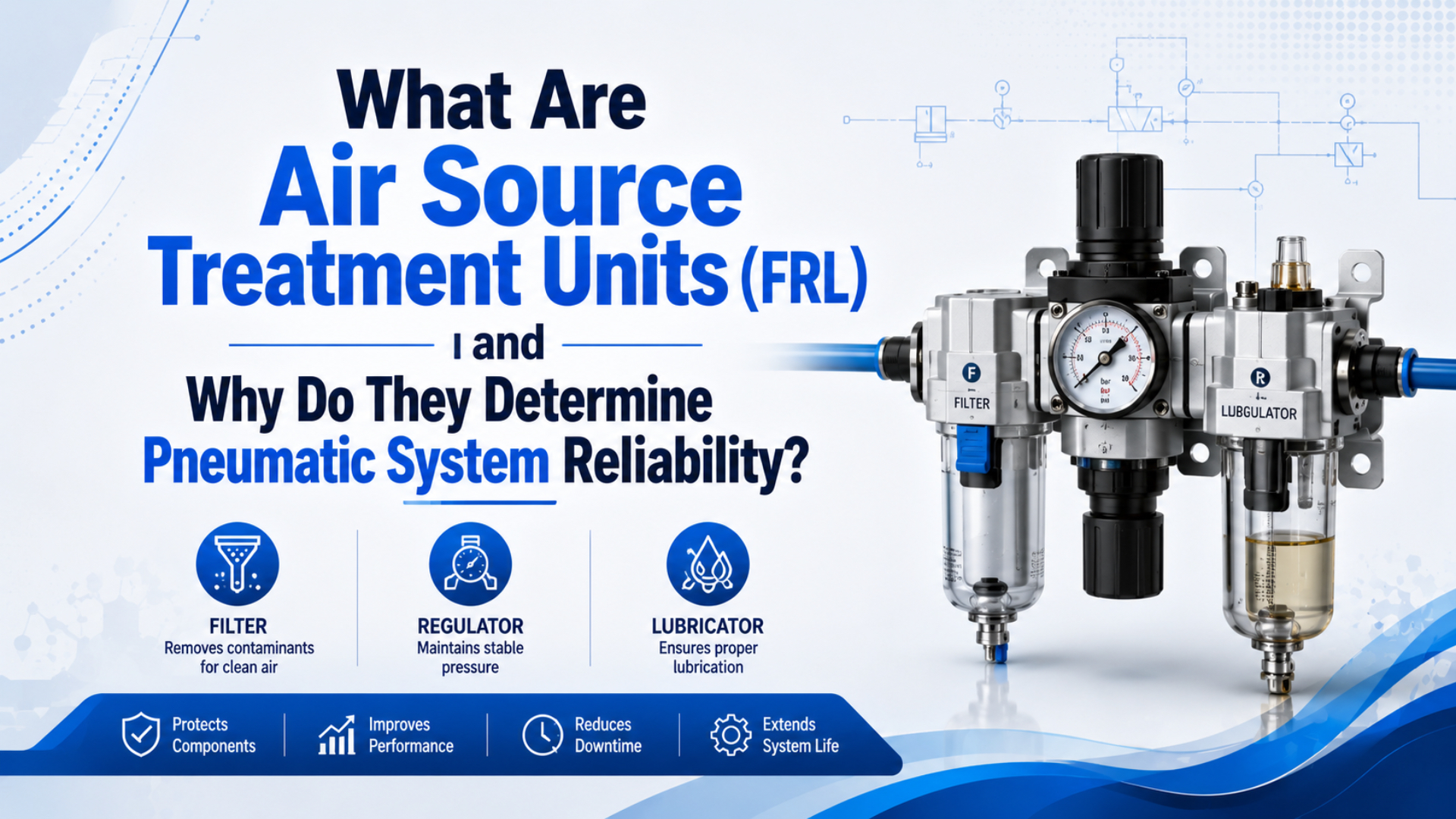
Air source treatment units, usually called FRL units, prepare compressed air near the machine before that air reaches valves, cylinders, grippers, and tooling. The three letters mean filter, regulator, and lubricator. In many modern circuits, the lubricator is optional, but filtering and pressure regulation are rarely optional.
The practical reason is reliability. A cylinder or valve may be well selected and still fail early if the point-of-use air is wet, dirty, over-pressurized, unstable, or starved by a small treatment unit. Treat the FRL as part of the actuator circuit, not as a generic accessory.
Key Takeaways
- ISO 8573-1 classifies compressed air by particles, water, and oil, so FRL selection should start with a point-of-use air-quality target.
- CAGI says well-designed compressed air systems should stay within 10 percent pressure drop from compressor discharge to point of use.
- CAGI also recommends changing filter elements when differential pressure exceeds 5-7 psig or at least every six months.
Use the RFQ data below to connect ISO air class, flow, pressure drop, moisture control, and safety requirements to measurable acceptance points.
The fastest FRL selection mistake is choosing by port thread alone. Port size tells you what can be screwed into the line. It does not prove the filter, regulator, bowl, drain, and internal passages can pass peak machine flow without unstable pressure.
What Are Air Source Treatment Units (FRL)?
Air source treatment units are point-of-use compressed-air preparation assemblies that remove contamination, regulate pressure, and sometimes add lubricant before air reaches pneumatic components. ISO 8573-1:2010 specifies compressed-air purity classes for particles, water, and oil, independent of where air is specified or measured (ISO 8573-1, 2010).
In a machine circuit, the FRL sits between the plant air line and the device that needs controlled air. It may feed one cylinder, a valve island, a fixture, or a full station. The location matters because air can change after the dryer or main filter. Old pipe, a wet drop leg, a small hose, or a clogged element can still send bad air to the machine.
Filter regulator lubricator means a three-function air-preparation assembly: filter first, regulator second, lubricator last when oil mist is allowed. Point-of-use air preparation is the local cleaning and pressure-control step at the machine, not just the compressor-room dryer or main header filter.
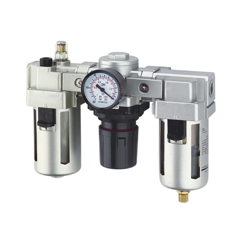
Use a dedicated FRL unit when a pneumatic station needs local control over air quality and pressure. Use a filter regulator when lubrication is not wanted. Use a stand-alone pressure regulator when upstream filtration and drying are already correct.
What Does Each FRL Component Do?
An FRL has three jobs: the filter removes particles and liquid water, the regulator sets downstream pressure, and the lubricator meters oil mist when the downstream device requires it. ISO 8573-1 separates air quality into particles, water, and oil, which maps directly to the filter and lubrication decisions (ISO 8573-1, 2010).
| FRL part | Main job | What to verify | Failure if ignored |
|---|---|---|---|
| Filter | Remove particles and liquid condensate | micron rating, bowl, drain, pressure drop | valve sticking, seal scoring, blocked passages |
| Regulator | Set stable downstream pressure | flow capacity, relieving type, gauge range | weak force, pressure sag, poor repeatability |
| Lubricator | Add controlled oil mist where needed | oil type, drop rate, distance to device | dry wear or oil contamination |
| Gauge or sensor | Show local pressure | range, accuracy, position | false confidence from wrong measurement point |
| Drain | Remove collected liquid | manual, semi-auto, or auto drain | water carryover and corrosion |
Many machines no longer use a lubricator because modern seals, clean processes, and oil-free requirements may not allow oil mist. That does not make the “L” meaningless. It means the drawing should say FR, FRL, or separate filter plus regulator based on the downstream component manuals.
For air-quality targets, connect this article to the dedicated ISO air quality standards guide. The ISO article sets the cleanliness language. This article turns that language into a hardware and maintenance decision.
Why Do FRL Units Determine Pneumatic System Reliability?
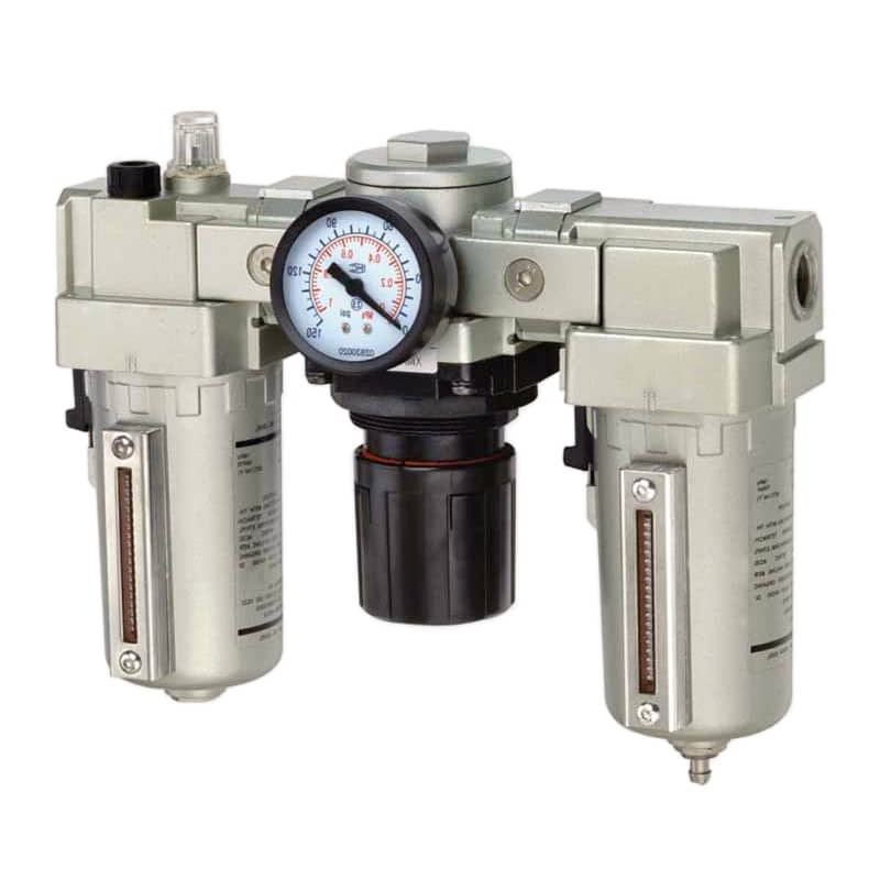
FRL units determine reliability because they decide whether the local circuit receives clean air, stable pressure, and acceptable pressure drop. CAGI says pressure drop occurs through piping, fittings, filters, dryers, and components, and most well-designed systems stay within 10 percent pressure drop to any point of use (CAGI Pressure Drop Technical Brief, 2026).
A cylinder failure is not always a cylinder problem. Contaminated air can scratch seals. Moisture can corrode bores and valves. Excessive pressure can increase impact and air consumption. Low flowing pressure can make a good actuator look undersized. In other words, the FRL often decides whether the downstream part works as designed.
Pressure drop is the loss between upstream supply pressure and downstream usable pressure while air is flowing. For example, a gauge that looks normal at idle can fall sharply when a clamp cylinder extends or several blow-off nozzles open together.
In our experience, repeat seal failures usually deserve an air-preparation review before another seal kit is ordered. We found that scoring, swelling, dry wear, or corrosion on the failed seal often points back to the local FRL, dryer, drain, and branch piping.
The downstream damage path often looks like this:
| Air problem | What the FRL can control | Typical machine symptom |
|---|---|---|
| Dirt or pipe scale | filtration at the point of use | sticky valves, scratched seals |
| Liquid water | separator bowl and drain strategy | corrosion, freezing, erratic speed |
| Oil carryover or wrong oil mist | filter choice and lubricator use | seal swelling, process contamination |
| Pressure set too high | regulator setpoint | impact, leakage, wasted air |
| Pressure sag under flow | FRL Cv and filter pressure drop | slow cylinders, weak clamps |
For downstream seal damage, link the FRL review with the industrial cylinder seal guide. The seal tells you what failed. The FRL review often explains why.
How Should You Size an FRL Unit for Flow and Pressure Drop?
Size an FRL from peak flow, acceptable pressure drop, regulator stability, port size, and point-of-use pressure, not from thread size alone. CAGI recommends air velocity through piping at 20 ft/s or lower and warns against raising compressor discharge pressure as the first response to low point-of-use pressure (CAGI Pressure Drop Technical Brief, 2026).
Start with the machine event that demands the most air. A slow setup jog may not expose the problem. A fast extend stroke, several cylinders firing together, or a blow-off event can make the regulator and filter sag even when the static gauge looks fine.
For example, a small fixture may pass a static pressure check and still fail during a two-cylinder clamp cycle. Measure the FRL outlet during the actual event, then compare that reading with the actuator pressure requirement.
Use this sizing path:
- Record supply pressure at the FRL inlet.
- Record required downstream pressure at the valve or actuator.
- Convert the machine demand into one flow unit.
- Check the FRL catalog flow curve or Cv at the allowed pressure drop.
- Confirm filter element condition and bowl/drain type.
- Measure pressure at the FRL outlet during the real cycle.
For the deeper flow-pressure relationship, use the air flow to pressure guide. For a pure pressure-drop troubleshooting workflow, use the pressure drop guide.
Which FRL Specifications Matter by Application?
The important FRL specifications are air-quality target, flow rating, pressure range, drain type, bowl material, port size, regulator behavior, environment, and whether lubrication is allowed. OSHA 1910.307 requires hazardous-location equipment to be approved for the class of location and specific gas, vapor, dust, or fiber present (OSHA 1910.307, 2026).
Do not treat “light”, “medium”, and “heavy” duty as universal technical grades. A small medical fixture may need stricter air quality than a large general-purpose cylinder. A heavy-duty sawmill actuator may need a rugged metal bowl and auto drain more than ultra-fine filtration.
| Application context | FRL decision focus | Common mistake |
|---|---|---|
| General packaging machine | FR or FRL, flow capacity, clear drain access | choosing by port thread only |
| Food or sanitary area | material compatibility, cleanability, oil-free policy | calling a component “FDA approved” without written facility requirements |
| Electronics or clean process | oil-free air, fine filtration, point-of-use test | adding lubricator oil where oil contamination is unacceptable |
| Outdoor or cold area | pressure dew point, freezing risk, metal bowl | ignoring winter line temperature |
| Hazardous location | approved electrical accessories and area classification | using ordinary switches or drains in classified areas |
| Fast cylinder station | Cv, pressure drop, regulator recovery | blaming the cylinder instead of the FRL |
For food handling or packaging, match the FRL body, bowl guard, drain method, lubricant policy, and cleaning plan to the facility rules. 21 CFR Part 110 covers current good manufacturing practice for manufacturing, packing, or holding human food (eCFR 21 CFR Part 110, 2026). It is not a shortcut label for every pneumatic part.
For moisture-sensitive applications, link the FRL decision to pressure dew point. The pressure dew point guide explains why a bowl filter cannot replace a correctly selected dryer when condensation risk is high.
How Should FRL Maintenance Be Planned?
FRL maintenance should be based on differential pressure, condensate load, regulator behavior, lubricator consumption, and visual inspection. CAGI says filter elements should be changed when differential pressure exceeds 5-7 psig or at least every six months, and that wet receiver tanks should be drained regularly (CAGI Pressure Drop Technical Brief, 2026).
Calendar maintenance alone is not enough. A filter on a clean, dry, low-flow branch may last longer than one on a dirty high-demand branch. A bowl in a humid plant may need frequent draining. A regulator that is correctly set at rest may still sag when the cycle starts.
Use this maintenance checklist:
| Check | Trigger | Action |
|---|---|---|
| Filter differential pressure | 5-7 psig or supplier limit | replace element |
| Bowl condensate | liquid visible or auto drain fault | drain, repair drain, check dryer |
| Regulator outlet pressure | droop during cycle | check flow rating, inlet pressure, filter |
| Gauge condition | unreadable or wrong range | replace or add sensor |
| Lubricator level | low level or no drop movement | refill with correct oil, verify need |
| Bowl, guard, bracket | cracks, clouding, loose mount | replace damaged hardware |
| Downstream symptoms | sticky valve, seal wear, slow actuator | inspect air quality and pressure drop |
From our testing and field reviews, the best FRL maintenance record is not a long note. We measured faster root-cause progress when the record included pressure before and after the filter, a bowl photo, and the fault cycle where pressure droop appeared.
FRL RFQ Checklist
An FRL RFQ should include pressure, flow, air-quality target, drain preference, port and tube size, downstream devices, environment, and lubrication policy. DOE’s compressed-air sourcebook emphasizes a systems approach that addresses current conditions, operating parameters, production needs, and interactions between supply and demand (DOE Sourcebook, 2022).
Before asking for a replacement or new FRL selection, collect:
- Inlet pressure range and required outlet pressure.
- Peak flow demand, with unit and duty cycle.
- Existing port size, tube size, and fitting layout.
- Required ISO 8573-1 particle, water, and oil targets if specified.
- Filter micron rating currently installed.
- Manual, semi-auto, or automatic drain preference.
- Bowl material preference, including metal bowl or bowl guard if needed.
- Whether downstream components allow oil mist.
- Ambient temperature and lowest expected line temperature.
- Hazardous, washdown, food, cleanroom, or outdoor requirements.
- Photos of the current FRL, gauge, drain, and downstream valve manifold.
- Notes on symptoms: pressure sag, water in bowl, sticky valves, seal scoring, or slow cylinder motion.
For motion problems, include the actuator context as well. A rodless cylinder may need a larger local FRL than the port thread suggests because long strokes and fast cycles expose pressure drop quickly. For custom review, send the data through technical support.
FAQs About Air Source Treatment Units FRL
FRL questions should be answered from point-of-use air quality, pressure, and flow. ISO 8573-1 covers particles, water, and oil purity classes, while CAGI gives practical pressure-drop and filter-change guidance for compressed-air systems (ISO 8573-1, 2010; CAGI, 2026).
What is the difference between an FRL and a filter regulator?
An FRL includes filter, regulator, and lubricator functions. A filter regulator combines only filtering and pressure regulation. Use FR when downstream equipment must stay oil-free or already has lifetime lubrication. Use FRL only when the component manual calls for oil mist or the circuit is designed for it.
Does every pneumatic system need a lubricator?
No. Many modern pneumatic cylinders, valves, grippers, and clean-process systems are specified for non-lubricated air. Adding oil can contaminate products, sensors, tubing, or exhaust areas. Confirm the downstream component manual before installing a lubricator or refilling an old one.
What micron filter should I choose for an FRL?
Choose the micron rating from the required air-quality target and component manual, not from a universal rule. ISO 8573-1 separates particles, water, and oil, so the filter choice should match the contaminant risk, pressure drop allowance, dryer performance, and point-of-use acceptance test.
Can an undersized FRL slow a cylinder?
Yes. If the filter, regulator, fittings, or internal passages cannot pass peak flow, outlet pressure can sag during the stroke. CAGI says pressure drop occurs through filters and other components, so measure pressure at the FRL outlet while the cylinder moves, not only while the system is idle.
How often should an FRL filter element be changed?
CAGI recommends changing filter elements when differential pressure exceeds 5-7 psig or at least every six months. In dirty, humid, or high-flow service, check more often. Use differential pressure, bowl condition, drain behavior, and downstream symptoms rather than calendar time alone.
What information is needed to size an FRL?
Provide inlet pressure, required outlet pressure, peak flow, duty cycle, port size, tube size, air-quality target, drain type, bowl material, environment, and lubrication policy. If the circuit already exists, add photos and pressure readings before and after the current FRL during the fault cycle.
Sources
- ISO 8573-1:2010, compressed-air purity classes for particles, water, and oil. Retrieved 2026-07-08.
- CAGI: Pressure Drop Technical Brief, 10 percent pressure-drop target, 20 ft/s velocity guidance, and 5-7 psig filter element guidance. Retrieved 2026-07-08.
- DOE: Improving Compressed Air System Performance, Third Edition, systems approach, operating data, demand review, and compressed-air maintenance framework. Retrieved 2026-07-08.
- OSHA 1910.307 Hazardous Classified Locations, hazardous-location classification and equipment approval requirements. Retrieved 2026-07-08.
- eCFR 21 CFR Part 110, current good manufacturing practice for manufacturing, packing, or holding human food. Retrieved 2026-07-08.
- AutomationDirect video: Air Prep Basics, FRL conditioning context for the embedded video. Retrieved 2026-07-08.