

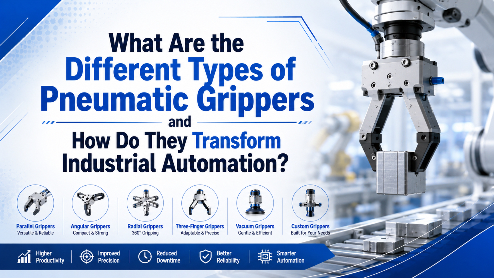
Pneumatic grippers are air-powered end-of-arm actuators that open and close jaws around a part. They transform automation when the jaw style, finger tooling, stroke, force, friction, and air supply match the real workpiece instead of a catalog photo. SMC describes pneumatic grippers as parts for pick-and-place applications and lists two, three, and four-finger parallel styles, angular grippers, wide-opening models, toggle models, and low-contamination versions (SMC, 2026).
The short version: use parallel grippers for square, flat, or repeatable parts; angular grippers for swing-clearance and open-access stations; three-jaw grippers for round centering; toggle grippers for hold force; and custom fingers whenever the part shape controls the grasp more than the actuator body.
Key Takeaways
- SMC lists two, three, and four-finger parallel pneumatic grippers, plus angular, wide-opening, toggle, and low-contamination options for pick-and-place work (SMC, 2026).
- Grip force is not only a catalog number. It depends on load mass, acceleration, friction, jaw count, finger length, and safety factor.
- CAGI recommends no more than 10% pressure drop from compressor discharge to point of use, so gripper force checks must include the valve, tube, and point-of-use pressure (CAGI, 2026).
Most gripper mistakes start one step too late. Teams compare bore sizes before they draw the contact points on the part. In our experience, the fastest selection review starts with a marked-up part image: where can the fingers touch, what surfaces are fragile, and what happens if air pressure drops during the move?
What Are Pneumatic Grippers?
Pneumatic grippers are compressed-air end effectors that clamp, hold, center, or release workpieces. SMC calls them grippers for pick-and-place applications and lists 2-, 3-, and 4-finger styles in the same product family (SMC, 2026).
The actuator body creates motion, but the fingers create the grasp. A piston, wedge, rack, cam, or linkage moves the jaws. Attached fingers then touch the workpiece. That separation matters because two grippers with the same bore can behave very differently when one has short steel fingers and the other has long urethane-coated fingers.
Parallel pneumatic grippers are jaw actuators whose fingers move in straight, opposite directions. Angular pneumatic grippers are jaw actuators whose fingers rotate through an arc. Three-jaw grippers are centering actuators that close three fingers toward a shared center. These definitions keep selection grounded in motion before force.
Which Pneumatic Gripper Types Should You Compare?
Start with jaw motion, part geometry, and contact surface. SMC’s pick-and-place category includes parallel, angular, wide-opening, toggle, and low-contamination styles, which is a practical sign that one gripper type cannot cover every automation station (SMC, 2026).
| Gripper type | Best fit | Watch point |
|---|---|---|
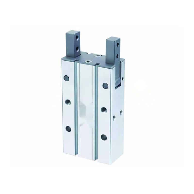
| Two-finger parallel gripper | Boxes, blocks, plates, machined parts, repeatable flats | Needs enough jaw stroke and parallel clearance |
| Three-jaw centering gripper | Round parts, shafts, bushings, bottle necks, centered loading | Check diameter range and equal finger contact |
| Angular gripper | Fixture clearance, short strokes, simple open-close transfer | Jaw force changes with finger angle and contact position |
| 180 degree angular gripper | Full open clearance around nests or loading pockets | Confirm open angle does not hit guarding or adjacent tools |
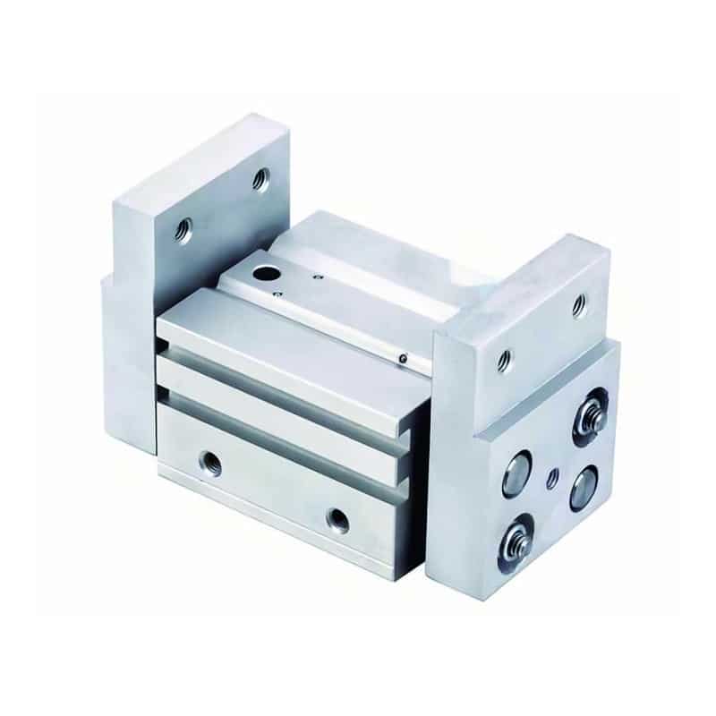
| Wide-opening parallel gripper | Mixed part sizes and long approach clearance | Long fingers increase moment load on jaws |
| Toggle gripper | Holding, retention, and clamp-like behavior | Verify release state and safe exhaust behavior |
| Low-contamination gripper | Electronics, optics, clean handling | Air quality and boot material become selection inputs |
For example, a conveyor pick of flat aluminum blocks usually points to a wide-opening parallel pneumatic gripper or a compact two-finger model. A round plug that must stay centered may point to a three-jaw unit. A fixture with high side walls may favor an angular pneumatic gripper because the fingers swing clear.
How Do Parallel and Angular Pneumatic Grippers Differ?
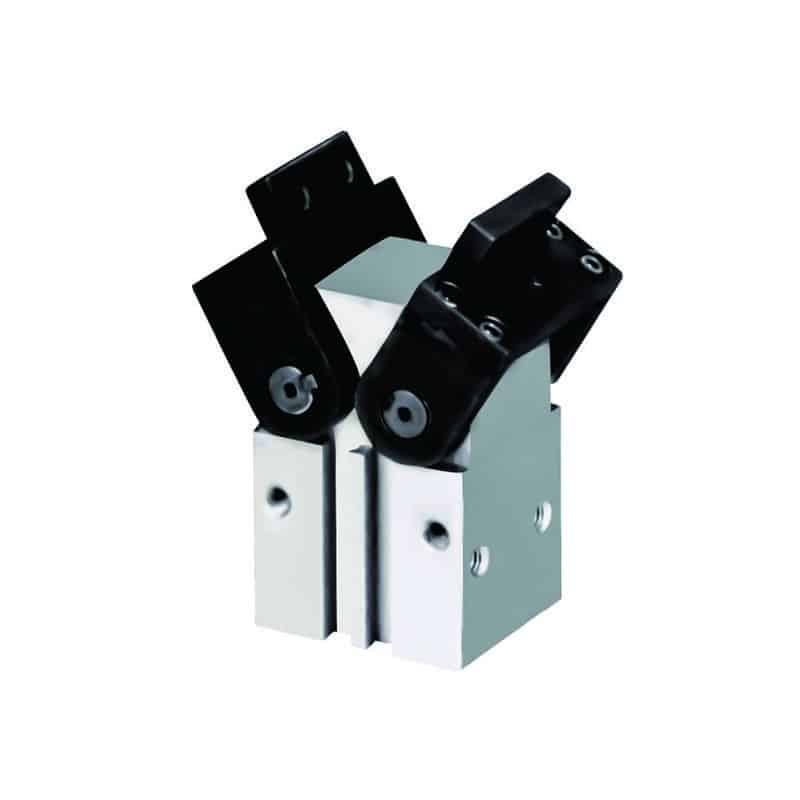
Parallel grippers move jaws along straight lines, while angular grippers pivot jaws through an arc. SMC lists parallel styles with two, three, and four fingers, and also lists angular models with speed adjustment in its gripper family (SMC, 2026).
Parallel grippers usually suit parts with predictable width. They keep the finger contact angle stable through the stroke, so they are easier to model when the workpiece has flats. However, they still need jaw guides that can carry side loads from long fingers. A compact parallel body can lose practical capacity when tooling shifts the contact point far from the jaw face.
Angular grippers suit stations where clearance matters more than linear jaw travel. The fingers rotate away from the part, which can help a robot or slide leave a tight nest. That said, force and contact geometry change through the opening angle. Check the catalog force curve at the actual contact point, not only at the closed position.
When Do 3-Jaw, Toggle, Needle, and Soft-Jaw Grippers Fit?
Use specialty grippers when the workpiece defines the contact more than the jaw body. SMC includes three and four-finger parallel styles, toggle support, and low-contamination models, while a 2025 gripper-adaptation study tested six gripper configurations across changing jaw widths (SMC, 2026; arXiv, 2025).
Three-jaw grippers are common for cylindrical parts because they center the workpiece as they close. Toggle grippers fit hold-down or retention jobs where the gripper must resist part movement after closing. Needle grippers can handle porous textiles, fiber mats, or soft sheets when vacuum leaks through the material. Soft jaws and custom pads handle cosmetic surfaces, curved parts, or mixed-friction contact.
Research also supports a practical shop-floor point: tooling details change grasp behavior. A 2025 fingerpad study reported that actuation pressure and timing changed friction force by up to a factor of 2.8 (arXiv, 2025). That does not mean every plant needs adaptive pads. It means jaw material, pad shape, and surface condition deserve the same review as bore size.
How Do You Size Grip Force Without Damaging the Part?
Size grip force from part load, acceleration, jaw count, and friction before you select a body size. A 2021 grasp-pose paper used gripper stroke, surface friction, and collision checking as selection criteria for suitable grasps (arXiv, 2021).
Use this starting formula for a vertical or dynamic pick:
Required force per jaw = m x (g + a) x safety factor / (friction coefficient x jaw count)This formula is a first screen, not the final approval. Add jaw moment, finger length, part offset, impact, air-pressure tolerance, and surface variation. Specifically, long fingers increase moment load on the gripper guide. Low-friction plastic needs more clamp force than rubber-contact metal. Fragile parts may need larger pads so the contact pressure stays below the damage limit.
Our team analyzed gripper RFQs where the catalog force looked adequate but the fingers were too long for the guide load. We also found the opposite problem: a larger gripper held the part but marked a coated surface. In both cases, the fix was not simply “more force.” The fix was contact area, finger length, pad material, and a more honest acceleration allowance.
Use the pneumatic gripper force calculator to test mass, acceleration allowance, safety factor, friction coefficient, jaw count, and available jaw force. If the calculator shows a narrow margin, do not solve it only by increasing pressure. Review the finger design and the point-of-use air supply first.
What Does Air Quality and Pressure Drop Change?
Air quality and pressure drop change repeatability, speed, force, and service life. ISO 8573-1 classifies compressed air by particles, water, and oil, and CAGI says every extra 2 psig of pressure can add about 1% compressor power (ISO, 2010; CAGI, 2026).
A gripper that works on a bench can miss parts on the machine if the valve island sees lower pressure during peak demand. CAGI says a well-designed compressed-air system should stay within 10% pressure drop from compressor discharge to point of use (CAGI, 2026). That is why the useful pressure value is the pressure at the gripper valve while the machine cycles.
Moisture and oil also matter. ISO 8573-1 covers particles, water, and oil purity classes for compressed air (ISO, 2010). Wet air can slow valves, wash lubricant, corrode fittings, and make small grippers sticky. For moisture targets, review pressure dew point in pneumatic systems. For force loss from plumbing, review pressure drop in pneumatic systems.
How Should You Choose Between Gripper, Vacuum, and Custom Fingers?
Choose the holding method from the part surface first. SMC’s cobot gripping page lists pneumatic grippers, electric grippers, vacuum grippers, and magnet grippers as separate gripping options, which reflects real end-effector tradeoffs (SMC, 2026).
Vacuum works well for flat, sealed surfaces with enough area. It struggles with porous material, heavy texture, holes, oil, and dusty surfaces. A pneumatic gripper works better when the part offers edges, holes, bosses, or a shape that fingers can locate. In contrast, a custom finger often beats a larger gripper when the part needs controlled orientation.
The 2025 gripper-adaptation study reported 93.3% average task success across six gripper configurations, compared with 23.3-26.7% baseline ranges in that research setup (arXiv, 2025). Treat that as research evidence for geometry-aware grasping, not as a production guarantee. In production, repeatability still depends on fixture tolerance, robot path, air quality, sensors, and part variation.
For broader actuator selection, compare this article with what pneumatic actuators are and how they work. If the jaw must rotate the part after gripping, also review pneumatic rotary actuator selection.
What Should Be on a Pneumatic Gripper RFQ Checklist?
Build the RFQ around the part, not only the gripper series. CAGI lists demand flow, pressure, and air quality as key compressed-air sizing parameters, and gripper selection adds workpiece geometry, jaw travel, and contact material to that list (CAGI, 2026).
Send these details before asking for a part number:
- Workpiece drawing or photos with allowed contact zones marked.
- Part mass, material, surface finish, oil, dust, burrs, and temperature.
- Required orientation, pick direction, robot or slide acceleration, and cycle rate.
- Available air pressure at the valve during machine operation.
- Finger length, approximate pad shape, and any offset from the jaw face.
- Required open clearance, nest geometry, and nearby collision risks.
- Sensor needs, such as open, closed, part present, or grip confirmation.
- Air quality target, including dryer, filtration, and point-of-use moisture expectation.
- Safety state on air loss, emergency stop, or part drop risk.
- Preferred product family, such as pneumatic grippers, 180 degree angular grippers, or custom fingers.
For a machine-specific gripper review, send the checklist with photos, drawings, contact surfaces, part weight, surface condition, cycle data, and pressure conditions.
FAQ
What are the main types of pneumatic grippers?
The main types are two-finger parallel grippers, three-jaw centering grippers, angular grippers, 180 degree angular grippers, wide-opening parallel grippers, toggle grippers, needle grippers, and low-contamination grippers. The right type depends on part geometry, stroke, clearance, friction, and the required safety state.
Should I choose a parallel or angular pneumatic gripper?
Choose a parallel pneumatic gripper when the part has stable width, flat contact surfaces, and predictable approach clearance. Choose an angular pneumatic gripper when the fingers must swing away from a nest, fixture, or adjacent tool. Always check force at the actual contact point.
How do I calculate pneumatic gripper force?
Start with part mass, acceleration allowance, safety factor, friction coefficient, and jaw count. A useful first estimate is required force per jaw equals mass times gravity and acceleration, times safety factor, divided by friction coefficient and jaw count. Then check finger length, offset, and jaw moment.
When should I use a pneumatic gripper instead of a vacuum cup?
Use a pneumatic gripper when the part has edges, holes, bosses, rough surfaces, porous material, oil, dust, or a shape that needs mechanical location. Use vacuum when the part has enough sealed, flat area and the holding force remains stable through acceleration.
What information should I send for a pneumatic gripper quote?
Send part photos or drawings, mass, material, surface finish, contact zones, required orientation, cycle rate, acceleration, available pressure at the valve, finger length, open clearance, sensor needs, air quality target, and the safe state on air loss.
Sources and Retrieval Notes
- SMC USA, “Grippers for Pick and Place,” retrieved 2026-07-08: https://www.smcusa.com/products/pneumatic-actuators/grippers~20234
- SMC USA, “Cobot Gripping Solutions,” retrieved 2026-07-08: https://www.smcusa.com/solutions/applications/collaborative-robot-grippers
- Compressed Air and Gas Institute, “Working with Compressed Air,” retrieved 2026-07-08: https://www.cagi.org/working-with-compressed-air/
- ISO, “ISO 8573-1:2010 Compressed air - Part 1: Contaminants and purity classes,” retrieved 2026-07-08: https://www.iso.org/standard/46418.html
- arXiv, “Grasp Adaptation in Operational Space,” 2025: https://arxiv.org/abs/2502.15613
- arXiv, “Pneumatic Grippers With Tunable Fingerpad Friction,” 2025: https://arxiv.org/abs/2502.00926
- arXiv, “6D Grasp Pose Generation and Evaluation for Robotic Bin Picking,” 2021: https://arxiv.org/abs/2104.11660
- YouTube video embedded for visual context: https://www.youtube.com/watch?v=sLcHqzLYHTk