

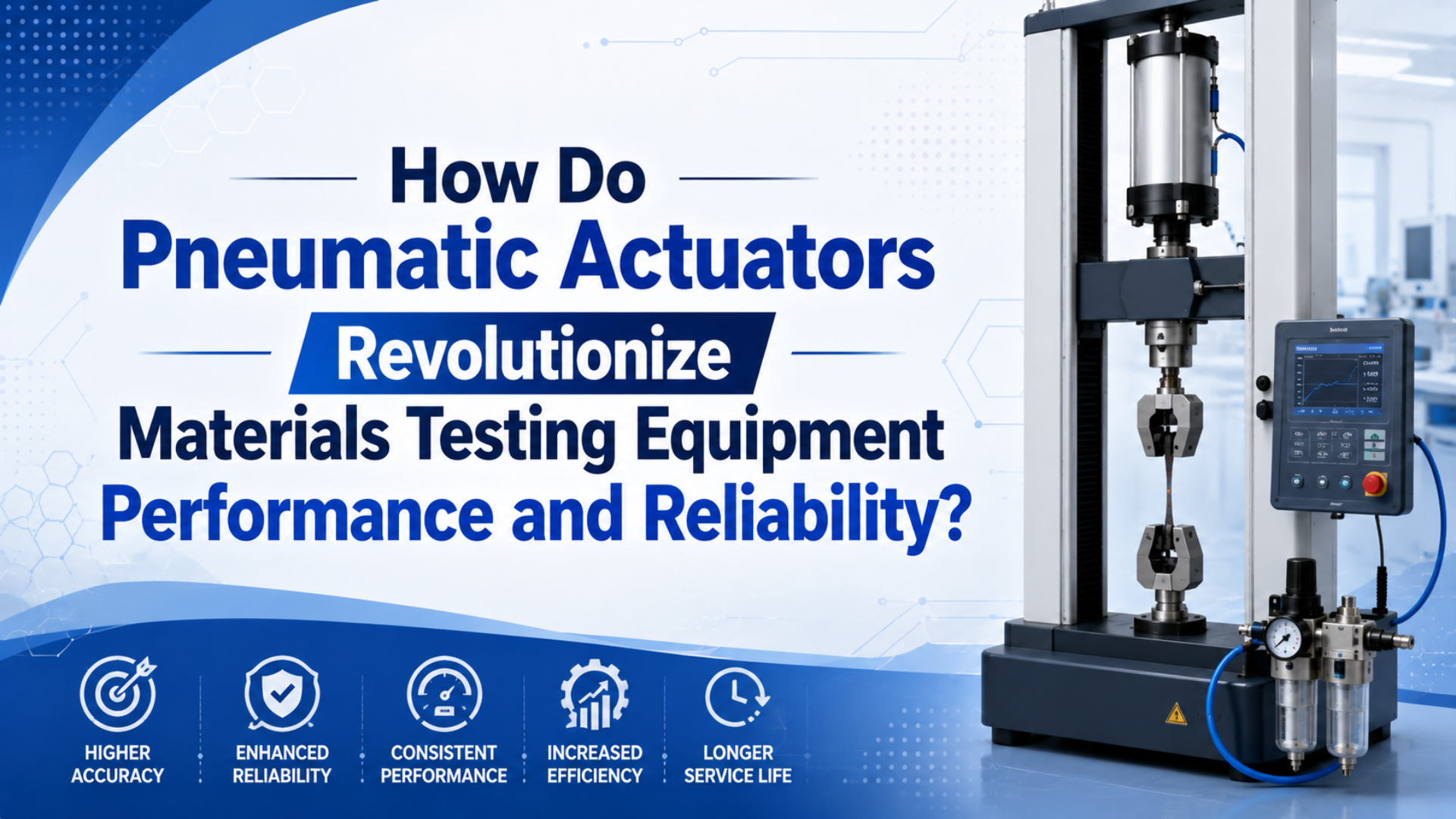
Pneumatic actuators improve materials testing equipment when they are used for the right motion job: specimen clamping, guard movement, grip actuation, fixture loading, ejecting tested samples, or moving a test head between repeatable positions. They do not replace the load cell, calibration procedure, or force verification standard.
That distinction matters. ASTM E4-24 covers force calibration and verification for tension or compression testing machines, but says the practices are not complete purchase specifications for testing machines (ASTM E4-24, 2024). Treat the actuator as part of the machine system, not as proof that the test result is valid.
Key Takeaways
- ASTM E4-24 is about force calibration and verification, not actuator marketing claims.
- ISO/IEC 17025:2017 remains current and sets laboratory competence requirements.
- CAGI says well-designed compressed-air systems should hold pressure drop to 10% or less.
Use the RFQ data below with ASTM, ISO, NIST, CAGI, Festo, Parker, and Enfield source checks before specifying a testing-equipment pneumatic actuator.
The useful upgrade question is not “Can pneumatics make the tester more accurate?” It is “Which machine motion is limiting repeatability, safety, throughput, or maintenance?” Pneumatics can solve fixture and auxiliary motion problems. The force-measurement chain still needs calibration evidence.
Where Do Pneumatic Actuators Fit in Materials Testing Equipment?
Pneumatic actuators fit best in materials testing equipment when the motion supports the test instead of defining the force measurement. ASTM E4-24 covers tension and compression testing-machine force calibration by force-measurement standards, while ISO/IEC 17025:2017 sets competence and consistent-operation requirements for testing and calibration laboratories (ASTM E4-24, 2024; ISO/IEC 17025, 2017).
Pneumatic actuators in materials testing equipment are compressed-air devices used to move fixtures, grips, guards, specimen loaders, ejectors, crosshead accessories, or support mechanisms around the actual measurement system. The load cell, force indicator, calibration chain, and test method still decide whether the result is acceptable.

Use pneumatics where simple force and repeatable motion help the operator. Common jobs include closing a pneumatic grip, pushing a specimen into a fixture, opening a guard, moving a support table, releasing a tested part, or shifting a rodless carriage across a long fixture.
Do not use a pneumatic actuator claim as a shortcut for test accuracy. A clamp can hold the specimen. A cylinder can move a fixture. A servo-pneumatic axis can position an auxiliary head. The test machine still needs force verification, traceable standards, method control, and documented uncertainty.
For the broader actuator family, link this article with the pneumatic actuator guide. For a precision technology comparison, use the cylinders vs electric actuators precision guide.
What Test-Machine Functions Should Pneumatics Handle?
Pneumatics should handle materials-test functions that benefit from fast, clean, simple, and repeatable movement. Festo lists load, precision, dynamic response, environment, and costs as the main actuator-selection criteria, and notes that pneumatic actuators suit fast repetitive movements with clearly defined end positions (Festo, 2026).
In testing equipment, that usually means the actuator handles a machine support function rather than the calibrated measurement. If the task has a fixed open/close, clamp/release, push/return, or guard/open state, pneumatics can be a good first option.
| Test-equipment function | Pneumatic actuator fit | What to verify |
|---|---|---|
| Pneumatic grip or clamp | High fit | clamp force, jaw geometry, specimen damage risk |
| Guard door or shield | High fit | safety state, speed, cushioning, sensor feedback |
| Specimen loader or ejector | High fit | stroke, force, part contact, cycle time |
| Long fixture traverse | Strong fit with rodless actuator | guide load, moment, stroke, pressure drop |
| Crosshead force measurement | Poor fit alone | load cell, calibration, machine stiffness |
| Multi-position recipe axis | Conditional | feedback, proportional valve, controller, tuning |
For example, a pneumatic grip may improve operator repeatability because each specimen sees the same closing sequence. However, it must not crush, bend, or pre-load the specimen before the test begins. That is a fixture problem, not a catalog-cylinder problem.
In our experience, testing-machine RFQs go wrong when the buyer asks for “more accuracy” but only describes a cylinder. We found that the useful diagnostic is where the error appears: specimen slip, grip misalignment, crosshead motion, pressure sag, sensor timing, or force calibration.
How Should Force, Stroke, and Flow Be Calculated?
Start with force, stroke, and flow because those 3 variables decide whether a pneumatic actuator can perform the support motion without disturbing the test. CAGI says pressure drop occurs through piping, fittings, filters, dryers, and components, and well-designed compressed-air systems should have no more than 10% pressure drop to point of use (CAGI Pressure Drop Technical Brief, 2026).
Force is the first screen. A pneumatic cylinder creates theoretical force from pressure and effective piston area. Then subtract friction, guide drag, seal load, side-load effects, and safety margin. Use real point-of-use pressure, not only compressor-room pressure.
Theoretical actuator force = working pressure x effective piston area
Usable fixture force = theoretical force - losses - safety margin
Flow is the second screen. A clamp with a short stroke may only need modest flow. A long rodless traverse or rapid ejector may need much more air than the port thread suggests. If the valve, tube, FRL, or fittings are undersized, the actuator can slow down or hit inconsistently.
Use these checks before approving a pneumatic axis:
- Define the motion: clamp, release, load, eject, traverse, or guard.
- Record the required force at the tooling interface.
- Calculate bore force at the lowest expected point-of-use pressure.
- Confirm stroke and mechanical clearance.
- Estimate required flow from stroke time and cylinder volume.
- Check valve Cv, tube ID, FRL capacity, and pressure drop.
- Measure pressure during the actual cycle.
Use the force and flow tool cards above before selecting valves, tubing, and actuator bore. For longer air paths, connect the result to the compressed-air pressure drop guide.
Rodless Cylinder Use in Testing Fixtures
Rodless cylinders help testing fixtures when the machine needs long travel without an extended rod occupying extra space. Parker lists OSP-P rodless actuators with 10-80 mm bore options, 6000 mm maximum stroke in the technical specs, 8 bar maximum operating pressure, and durability-test-bench use among its applications (Parker OSP-P, 2026).
That makes rodless cylinders useful around long specimens, moving supports, fixture shuttles, guard doors, environmental-chamber loading, or test benches where the carriage must travel beside the frame. The compact geometry helps keep the motion inside the equipment envelope.
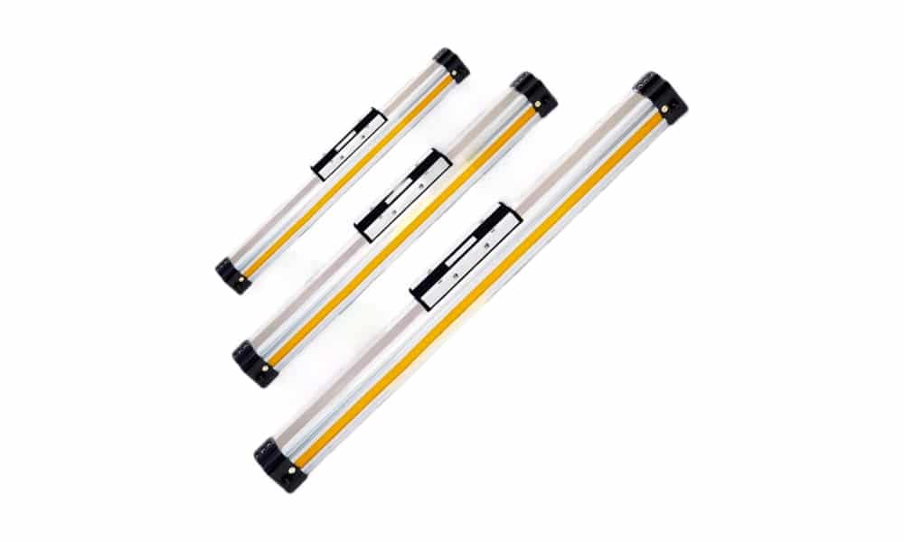
The risk is guide loading. A materials test fixture can apply off-center loads, twisting moments, or shock when a specimen fails. A rodless actuator should not be asked to carry uncontrolled bending moment unless its guide system is rated for the actual load path.
Use rodless designs when you need:
- Long travel near the test frame.
- A moving carriage instead of a protruding rod.
- Better packaging around guards or chambers.
- A shuttle for specimens, tooling, cameras, or supports.
- Point-to-point motion where end position is enough.
Use a different technology when the axis needs synchronized motion, many recipe positions, micron-class positioning, or a calibrated measurement role. In those cases, compare electric motion or a feedback-based servo-pneumatic package. The rodless cylinder definition guide is the better next read for mechanism details.
When Is Servo-Pneumatic Control Worth Considering?
Servo-pneumatic control is worth considering when a testing accessory needs controlled intermediate movement, soft positioning, or force-limited auxiliary motion. Festo describes servo-pneumatic systems as a cylinder with displacement encoder, proportional directional control valve, and positioning controller, and says they are attractive when masses above 10 kg are moved (Festo Actuators and Drives, 2026).
That architecture matters because a normal on-off valve gives two main states. It can extend and retract. It can confirm position with sensors. It cannot, by itself, prove a controlled path, hold many recipe positions, or reproduce a force profile.
Servo-pneumatic positioning means closed-loop pneumatic motion using feedback and a proportional valve. Enfield describes its S2 system as combining a proportional valve, sensors, and embedded control electronics so cylinders and actuators can stop at mid-stroke positions, follow profiles, or reduce end slamming (Enfield Technologies, 2026).
Use servo-pneumatic control carefully in a lab machine. Air compressibility, seal friction, tube volume, load changes, and fixture stiffness affect control behavior. The system can be useful for a moving support, pre-positioning axis, soft landing, or fixture adjustment. It should not be represented as automatic proof of force accuracy.
| Requirement | Basic cylinder | Servo-pneumatic | Electric actuator |
|---|---|---|---|
| Two hard stops | Strong fit | Overbuilt in many cases | Possible |
| Mid-stroke accessory position | Limited | Good fit when tuned | Strong fit |
| Many stored recipes | Weak | Conditional | Strong fit |
| Soft compliance | Natural advantage | Strong fit | Needs control strategy |
| Force measurement traceability | Not sufficient | Not sufficient | Not sufficient |
If the buyer says “test accuracy,” ask for the test method and calibration requirement. If the buyer says “move the fixture to 3 setup positions,” servo-pneumatic or electric motion may be the real comparison.
Reliability Checks Before a Retrofit
Reliability in a pneumatic testing-machine retrofit starts with air quality, point-of-use pressure, safe failure state, and documented calibration boundaries. CAGI recommends air velocity through piping at 20 ft/s or lower and changing filter elements when differential pressure exceeds 5-7 psig or at least every six months (CAGI, 2026).
The actuator can be correctly sized and still fail in service if the air system is unstable. Water, oil carryover, clogged filters, small tubing, undersized valves, and regulator droop can turn a good fixture into an inconsistent fixture.
From our testing and field reviews, pressure during motion is the reading that changes the conversation fastest. We measured cases where idle pressure looked acceptable while the actuator sagged during a fixture close or a long rodless-cylinder traverse.
Check these before replacing parts:
| Check | Why it matters in testing equipment | Evidence to collect |
|---|---|---|
| Point-of-use pressure during motion | Static pressure can hide cycle sag | gauge or sensor trend at the actuator |
| Air quality and FRL condition | Moisture and particles affect seals and valves | filter bowl photo, element age, drain status |
| Valve and tube sizing | Undersized flow path changes speed and force | valve Cv, tube ID, length, fittings |
| Fixture stiffness and alignment | Motion repeatability fails if the load path bends | drawing, guide style, moment load |
| Safety state | Test frames can expose operators to pinch force | valve fail state, guards, exhaust behavior |
| Calibration boundary | Retrofit must not invalidate the test method | calibration report and method scope |
For air preparation, use the FRL guide. For pressure-drop diagnosis, compare the measured point-of-use pressure with the CAGI pressure-drop guidance above.
The best retrofit notes separate “machine function improved” from “test result remains valid.” A new actuator can reduce specimen handling variation, but the lab still needs calibration evidence for the measurement chain.
Testing-Lab RFQ Checklist
A testing-lab RFQ should include motion data, measurement boundaries, safety state, air-system data, and calibration constraints. NIST says its traceability policy supports customers in establishing traceability of measurement results, while ASTM E4-24 requires force verification methods with specific uncertainty and SI traceability (NIST, 2019; ASTM E4-24, 2024).
Send enough information for the supplier to separate actuator sizing from test validity. A good RFQ does not ask for “0.1 mm testing accuracy” without saying whether that refers to actuator position, crosshead motion, specimen alignment, displacement measurement, or force reading.
Include:
- Testing machine type: tensile, compression, fatigue, bend, peel, puncture, or fixture-only.
- Actuator job: grip, clamp, guard, loader, ejector, traverse, support, or adjustment.
- Required force at the tooling interface.
- Stroke, move time, duty cycle, and cycle rate.
- Working pressure at the machine during motion.
- Valve voltage, PLC signals, sensor type, and feedback requirement.
- Fixture drawing with load direction and moment arm.
- Specimen material and damage sensitivity.
- Required safety state on air loss or power loss.
- Relevant test method, calibration scope, and lab accreditation constraints.
- Photos of the current actuator, valve, FRL, tubing, and mounting.
For a cylinder-first review, compare the data with when to choose a cylinder over an electric actuator. For a replacement discussion, include cylinder and rodless-cylinder photos only after the measurement boundary is clear.
FAQs About Pneumatic Actuators in Materials Testing Equipment
FAQ answers should separate actuator performance from testing-machine verification. ISO/IEC 17025:2017 sets competence and consistent-operation requirements for laboratories, and ASTM E4-24 covers force calibration and verification for tension and compression testing machines (ISO/IEC 17025, 2017; ASTM E4-24, 2024).
Can pneumatic actuators improve materials testing repeatability?
Yes, when the variation comes from handling, clamping, guarding, specimen loading, or auxiliary fixture motion. Pneumatic actuators can make those motions more consistent. They do not automatically improve load-cell accuracy, displacement measurement, calibration uncertainty, or compliance with the test method.
Can a pneumatic actuator replace a hydraulic actuator in a test frame?
Sometimes for fixture motion, low-to-moderate force support tasks, or auxiliary axes. It is not a universal replacement for a hydraulic loading axis. Compare required force, stiffness, speed, duty cycle, control mode, safety state, and test method before changing the drive technology.
Are rodless cylinders useful in tensile or compression test equipment?
Rodless cylinders are useful when the test equipment needs long auxiliary travel in a compact space, such as specimen shuttles, support tables, guards, or fixture traverse axes. They are not automatically better for measurement. Check guide load, bending moment, stroke, speed, and pressure drop.
Does servo-pneumatic control make a pneumatic axis precise?
It can make a pneumatic axis position-controlled, but it does not remove air compressibility or fixture mechanics. Festo describes servo-pneumatic systems as cylinder, encoder, proportional valve, and controller packages. Use them when the accessory motion needs feedback, not as proof that test force is calibrated.
What is the first calculation for a testing-machine pneumatic actuator?
Start with usable force at the tooling interface: working pressure times effective area, minus friction, guide drag, seal load, and safety margin. Then check stroke time, flow demand, valve capacity, tube ID, point-of-use pressure, and the failure state.
What should be removed from a testing-equipment actuator claim?
Remove unsupported universal claims about percentage ROI, certification savings, force accuracy, maintenance reduction, and delivery time unless they come from the lab’s documented data or a supplier-specific controlled study. Standards such as ASTM E4 and ISO/IEC 17025 support calibration boundaries, not generic marketing numbers.
Sources
- ASTM E4-24: Standard Practices for Force Calibration and Verification of Testing Machines, force calibration and verification scope, SI traceability, and warning that the practices are not complete purchase specifications. Retrieved 2026-07-08.
- ISO/IEC 17025:2017, testing and calibration laboratory competence, impartiality, and consistent-operation requirements; confirmed current in 2023. Retrieved 2026-07-08.
- NIST: Metrological Traceability FAQ and Policy, traceability policy and calibration-support context. Retrieved 2026-07-08.
- CAGI: Pressure Drop Technical Brief, 10% pressure-drop target, 20 ft/s velocity guidance, and 5-7 psig filter-element guidance. Retrieved 2026-07-08.
- Festo: Pneumatics or electrics? How to make the right choice, actuator-selection criteria and pneumatic/electric fit boundaries. Retrieved 2026-07-08.
- Festo: Actuators and drives, actuator definition, pneumatic drive context, and servo-pneumatic system architecture. Retrieved 2026-07-08.
- Parker: OSP-P Rodless Cylinders, bore, stroke, pressure, force, and application data for rodless actuator selection. Retrieved 2026-07-08.
- Enfield Technologies: S2 Cylinder Positioning System, servo-pneumatic positioning architecture and mid-stroke motion context. Retrieved 2026-07-08.
- Enfield Technologies YouTube video: S2 Positioning - Better Rodless Cylinder Positioning, visual reference for feedback-based rodless cylinder positioning. Retrieved 2026-07-08.