

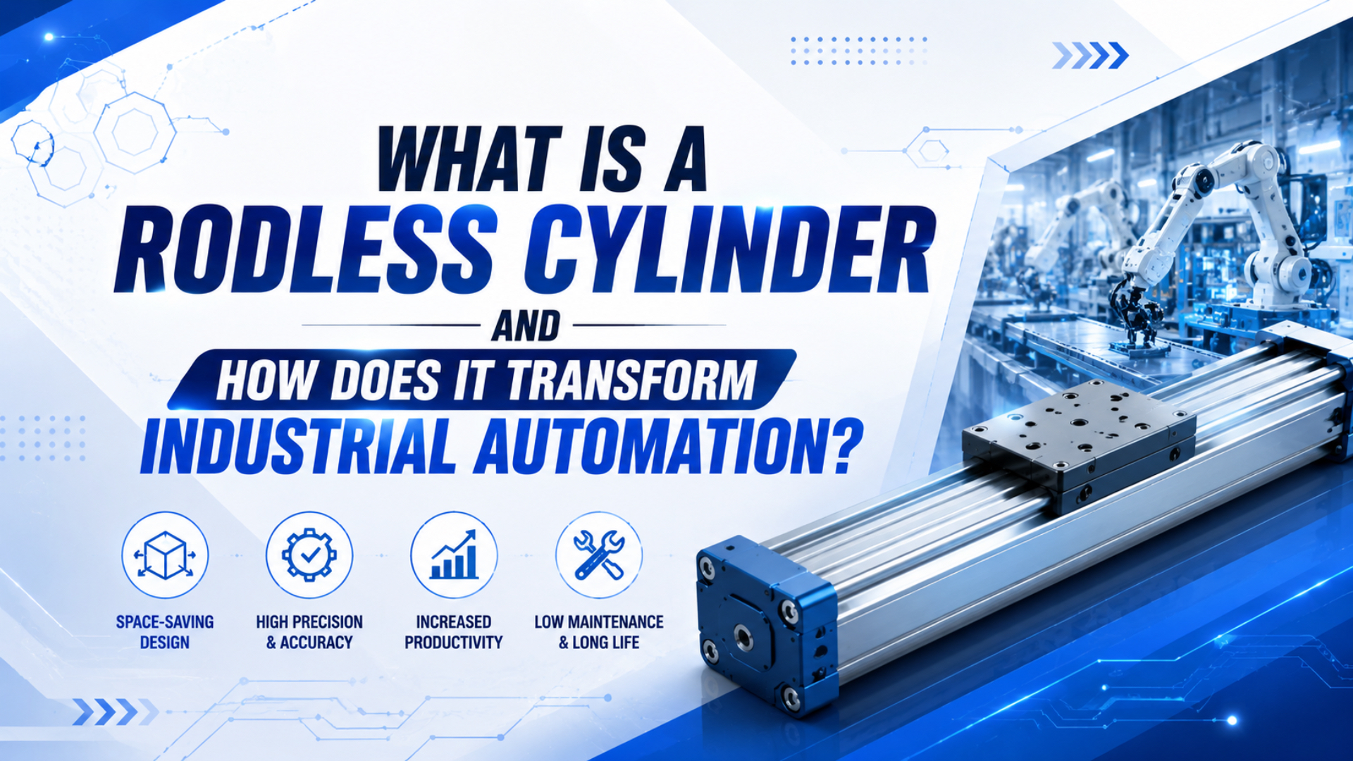
A rodless cylinder is a pneumatic linear actuator that moves a load with an external carriage instead of an exposed piston rod. The piston stays inside the cylinder body. The carriage moves beside the body through a magnetic or mechanical coupling, so the machine doesn’t need extra clearance for a rod to extend.
That one geometry change matters in automation. It can shorten a machine frame, reduce rod-buckling risk on long strokes, simplify carriage mounting, and make a replacement quote easier to compare. It doesn’t remove sizing work, though. You still have to check pressure, bore, load, moment, speed, cushioning, guide support, seals, and contamination.
Key Takeaways
- SMC defines rodless cylinders as actuators with no piston rod outside the body, using an internal piston connected to an external carriage (SMC, 2026).
- Parker lists OSP-P bores from 10-80 mm and 8 bar maximum operating pressure.
- Force math must use
F = P x A; a 63 mm bore at 6 bar is about 1,870 N before losses, not 18,760 N.
What Is a Rodless Cylinder?
A rodless cylinder has no piston rod extending outside the body; SMC describes the internal piston as connected to an external carriage by magnetic or mechanical coupling (SMC Rodless Actuators, 2026). In practical terms, it is still a pneumatic cylinder, but the moving interface sits on a carriage.
In a standard rod cylinder, compressed air pushes a piston and the rod carries motion outside the tube. In a rodless cylinder, compressed air still pushes the piston, but the piston moves a carriage along the cylinder profile. That carriage becomes the mounting point for tooling, a pusher, a clamp plate, a glue head, a transfer arm, or a sliding fixture.
This is the simplest definition:
Rod cylinder: piston drives an external rod.
Rodless cylinder: piston drives an external carriage.
The difference sounds small until the stroke gets long. A rodded cylinder needs space for the body and the extended rod. A rodless cylinder keeps the moving load close to the actuator body, which is why it appears so often in long-stroke packaging, conveyor, inspection, printing, assembly, and material-handling equipment.
The name “rodless” can mislead buyers. The useful question isn’t only “does it have a rod?” It is “where does the load path go?” If the load hangs far from the carriage, the guide and moment rating matter more than the cylinder bore.
How Does a Rodless Cylinder Work Internally?
Rodless cylinders transfer internal piston motion to an external carriage; AutomationDirect explains that the piston connects to a carriage moving alongside the body, which lets the actuator fit tighter spaces than a rodded design (AutomationDirect, 2020). The transfer method decides force limit, leakage risk, and contamination tolerance.
There are three common transfer styles.
Magnetic coupling uses magnets on the piston and carriage. The tube stays closed, and magnetic force passes through the wall. This design is clean and simple, but the carriage can decouple if the load or acceleration exceeds the magnetic coupling capacity.
Mechanical joint or band style cylinders use a slot, sealing band, and mechanical carriage connection. These can transmit higher force than many magnetic designs, but the sealing strip and wiper system must be protected from dirt, chips, washdown, and careless handling.
Cable styles use an internal piston connected to cable runs and pulleys. They can suit long travel, but cable stretch, tension, pulley condition, and end alignment become part of maintenance.
What Are the Main Rodless Cylinder Types?
Parker’s OSP-P catalog lists a double-acting rodless cylinder series with 10-80 mm bores, adjustable end cushioning, position-sensing capability, and 8 bar maximum operating pressure (Parker OSP-P catalog, 2025). That is one product family, but practical type categories are broader for selection.
Start by splitting designs into magnetic and mechanical types. Magnetic designs keep the tube closed and are attractive where cleanliness matters. Mechanical joint designs connect the piston and carriage through a sealing system and usually suit higher force transfer.
Guidance is the second split. A plain rodless cylinder provides linear drive, not a full load-bearing slide. A guided rodless cylinder adds rail, slide bearing, cam follower, or linear guide support so the carriage can handle moment loads. If tooling hangs off the side, start your selection there.
Controls create the third split: basic motion versus controlled positioning. Most pneumatic rodless cylinders are best for end-to-end movement, with sensors confirming end or intermediate positions. Mid-stroke control can be done, but it needs valves, feedback, stops, brakes, or a servo-pneumatic package.
| Type | Best fit | Main check before buying |
|---|---|---|
| Magnetically coupled | Clean, moderate-load travel | Coupling force, decoupling behavior, magnetic debris |
| Mechanical joint or band | Higher force transfer and general factory use | Sealing band condition, wipers, contamination |
| Guided rodless cylinder | Loads with offset, pitch, roll, or yaw moment | Allowable moments, guide life, mounting flatness |
| Servo-pneumatic rodless axis | Velocity profiles or repeatable mid-stroke stops | Feedback device, valve flow, controls, tuning time |
When Should You Choose Rodless Over a Rodded Cylinder?
Choose rodless when the machine can’t spare rod-extension space, especially on long strokes; SMC says rodless cylinders suit long-stroke applications because they avoid rod overhang, bending, piston binding, and uneven seal wear (SMC, 2026). The decision starts with envelope, then moves to load and guide checks.
A rodded cylinder can be the better part for short, simple strokes. It is familiar, available, and easy to mount. If the rod has space to extend, the load is well guided elsewhere, and cost matters most, a standard ISO or NFPA cylinder may win.
A rodless cylinder starts to make more sense when the stroke is long enough that the rod becomes awkward. It also helps where the moving element must stay inside a frame, under a guard, beside a conveyor, or below overhead clearance limits. AutomationDirect gives examples such as glue stations and vertical punch applications where the compact package solves installation issues.
What usually decides the case? Not the catalog photo. It’s the installed envelope with tooling, guards, sensors, fittings, cable loops, mufflers, stops, and service access drawn in.
In replacement work, the failed unit is rarely the whole story. We’ve found that successful rodless-cylinder replacement depends on measuring the carriage offset and stop method, not just reading the bore and stroke from the old label.
Sizing and Force Calculation Checks
Force must be calculated from pressure and piston area; NASA defines pressure as force divided by area, so actuator force follows F = P x A before losses (NASA Glenn Research Center, 2024). At 6 bar, a 63 mm bore cylinder gives about 1,870 N theoretical force, not 18,760 N.
The common mistake is mixing units. Pressure in bar, bore in millimeters, and force in newtons can work together, but only after conversion. One bar is 0.1 N/mm2. So 6 bar is 0.6 N/mm2.
Piston area = pi x bore^2 / 4
Theoretical force = pressure x piston area
Example, 63 mm bore at 6 bar:
Area = 3,117 mm2
Pressure = 0.6 N/mm2
Force = 1,870 N before friction and losses
Use theoretical force as a starting point, not as the usable load limit. Seal friction, guide friction, pressure drop, tubing length, valve flow, acceleration, cushioning, orientation, and safety factor all reduce what the machine can use.
For quick RFQ screening, I use three numbers before model matching: theoretical force, load moment at the carriage, and stopping energy at the target speed. If one fails, bore alone won’t save the application.
| Bore | Theoretical force at 6 bar | What to check next |
|---|---|---|
| 32 mm | 483 N | Light tooling, friction, guide drag |
| 50 mm | 1,178 N | Valve flow and cushioning |
| 63 mm | 1,870 N | Moment load and stop energy |
| 80 mm | 3,016 N | Tube support and mounting rigidity |
| 100 mm | 4,712 N | Frame stiffness and air consumption |
What Problems Cause Rodless Cylinder Failure?
Seal and guide problems should be expected maintenance items; Sealing & Contamination Control Tips lists nitrile, fluoroelastomer, and polyurethane as common pneumatic-cylinder seal materials, each chosen for different operating conditions (Sealing & Contamination Control Tips, 2023). In rodless cylinders, seal choice sits beside coupling and carriage checks.
Leakage is the first failure group. Band-style cylinders depend on sealing strips, piston seals, end seals, and wipers. Dirt under a strip or a scratched profile can turn a small leak into unstable motion.
Carriage or guide wear comes next. A rodless cylinder carriage is tempting to use as a structural slide. Sometimes that is fine, but only when the catalog allows the moment load. Offset tooling can create pitch, roll, and yaw loads that are much higher than the cylinder force calculation suggests.
End impact is another common failure path. A cylinder may have adjustable cushions, but cushions are not magic brakes. High speed, heavy tooling, short deceleration distance, blocked exhaust, or poor flow control can make the carriage hit hard at the end.
Magnetic decoupling belongs on the checklist for magnetic designs. The carriage can lose the piston if force demand exceeds coupling capacity. The symptom looks strange: the piston moves, but the carriage lags, stops, or snaps back when load changes.
Installation and Maintenance Checklist
Parker lists OSP-P operation with filtered compressed air and permanent grease lubrication, plus options such as Viton seals, clean-room versions, stainless screws, and air connections on one end (Parker OSP-P catalog, 2025). Those details show why installation is not just bolt pattern matching.
Start with the mounting surface. Long profiles can twist if the base is uneven. Check flatness, support spacing, end-cap access, carriage clearance, and whether the cylinder needs intermediate support on long strokes.
For the air path, use a filter appropriate to the plant air quality. Size tubing and valves for the target speed, not only for port thread size. A small valve can make a large cylinder behave weakly because pressure at the actuator drops during motion.
Next, check the moving load. Keep the load center close to the carriage. If the load must be offset, confirm pitch, roll, and yaw moment limits. Add external linear guides when the cylinder should drive motion but not carry the full load path.
Finally, set a maintenance rhythm that matches duty and environment. Inspect for leaks, carriage play, strip damage, wiper wear, loose mounting screws, and hard end impact. Clean magnetic surfaces and guide rails when debris can collect.
How Does a Rodless Cylinder Support Automation Design?
Rodless cylinders support compact automation because the stroke sits in the actuator envelope; AutomationDirect describes them as fitting within machine footprints where rodded cylinders would overhang, including glue-head and punch-station examples (AutomationDirect, 2020). That changes layout, guarding, and service access.
In packaging machines, a rodless cylinder can move a pusher, diverter, or glue head across a product path without pushing a rod into a walkway. In inspection systems, it can carry a camera or sensor carriage along a fixed rail line. In assembly equipment, it can shuttle fixtures between stations while keeping the axis tucked inside the frame.
Safety is not automatic. OSHA’s machine guarding guidance says machine parts and functions must be safeguarded when they can cause injury (OSHA Machine Guarding, 2026). A rodless cylinder removes an exposed rod, but the carriage, tooling, pinch points, and stops still need guarding.
Design clarity is the payoff. A rodless cylinder makes one axis easier to package, especially where the load already needs to travel beside a frame. It also makes the RFQ more precise because the buyer can define stroke, carriage load, guide style, stop method, and sensor needs as one motion package.
What Should You Send for a Replacement or New RFQ?
SMC’s MY1B catalog shows that rodless selection involves bore, stroke, operating pressure, piston speed, guide style, load, and allowable moment, with many MY1 variants built around different guide arrangements (SMC MY1B catalog, 2025). A useful RFQ needs more than a photo.
Send the old model number, bore, stroke, mounting style, port position, sensor type, and any label photos. If the label is missing, measure body length, travel, profile width, carriage dimensions, mounting holes, and port threads.
Send the application data too. Include moving mass, load offset from the carriage, mounting orientation, speed target, cycle rate, stop method, working pressure during motion, valve size, tubing size, and environment. Mention dust, washdown, metal chips, oil mist, food contact, low temperature, or clean-room requirements.
If you are replacing a failed cylinder, describe the failure plainly. Did it leak, bind, slam, drift, decouple, lose sensors, break a strip, or wear the guide? The failure mode often points to a better replacement than a direct copy.
Conclusion
A rodless cylinder is best understood as a 2-part pneumatic actuator: an internal piston and an external carriage, with the load moved along the cylinder body instead of on an exposed rod (SMC, 2026). That layout can transform automation design, but only when force, moment, speed, and environment are checked.
Use rodless cylinders when the stroke is long, the frame is tight, the load should stay beside the machine, or an exposed rod creates packaging trouble. Use rodded cylinders when the stroke is short, the rod has room, and the load is guided elsewhere.
For practical selection, define the envelope, calculate force correctly, check carriage moment, select the transfer style, size valves and tubing, decide the stop method, and protect the seals. Do that, and the rodless cylinder becomes a clean automation tool instead of an expensive guess.
FAQs About Rodless Cylinders
SMC, Parker, NASA, and AutomationDirect each answer a different part of the rodless-cylinder question: definition, catalog limits, force math, and machine layout (SMC, 2026; Parker, 2025; NASA, 2024; AutomationDirect, 2020). The short answers below are written for quick selection and replacement checks.
What is a rodless cylinder in simple terms?
A rodless cylinder is a pneumatic actuator where the piston stays inside the body and moves an external carriage. SMC describes the connection as magnetic or mechanical coupling. It does the same basic job as a linear cylinder, but it avoids the external rod that would extend past the machine frame.
How is a rodless cylinder different from a standard air cylinder?
A standard air cylinder pushes or pulls with a piston rod, so the machine needs room for rod extension. A rodless cylinder moves the load on a carriage beside the body. That makes it useful for long strokes, tight frames, and applications where a rod would interfere with tooling or guarding.
Are rodless cylinders stronger than rodded cylinders?
Not automatically. Cylinder force still follows pressure times piston area. At 6 bar, a 63 mm bore gives about 1,870 N theoretical force before losses. The rodless advantage is compact travel and carriage-based load movement, not a free increase in force. Check bore, pressure, guide load, and moment.
What usually fails first on a rodless cylinder?
Common early failures include air leakage, sealing-band wear, guide play, hard end impact, magnetic decoupling, sensor faults, and carriage binding. The root cause is often application mismatch: too much offset load, dirty air, poor support, undersized valves, excessive speed, or a stop method that overloads the carriage.
Can a rodless cylinder stop in the middle of the stroke?
Yes, but a plain directional valve usually gives end-to-end motion, not controlled positioning. Mid-stroke stops may need external stops, shock absorbers, brakes, proportional valves, position feedback, or a servo-pneumatic controller. Enfield’s S2 demo shows a guided Parker Origa rodless cylinder controlled with external feedback.
What information is needed to replace a rodless cylinder?
Send the model code, bore, stroke, mounting style, port location, sensor type, moving mass, load offset, orientation, speed target, pressure during motion, valve and tube size, stop method, cycle rate, environment, photos, and failure symptoms. Bore and stroke alone rarely explain why the old unit failed.
Sources
-
SMC: Rodless Actuators, definition of rodless actuators as internal-piston, external-carriage cylinders with magnetic or mechanical coupling, plus long-stroke suitability. Retrieved 2026-06-03.
-
Parker: OSP-P Pneumatic Rodless Cylinders and Linear Guides catalog, OSP-P bore range, 8 bar maximum pressure, compressed-air requirements, sealing options, and long-stroke notes. Retrieved 2026-06-03.
-
SMC: MY1B Mechanically Jointed Rodless Cylinder catalog, bore, pressure, speed, guide, load, and allowable-moment selection context. Retrieved 2026-06-03.
-
NASA Glenn Research Center: Air Pressure, pressure relationship
P = F / Aused for force calculations. Retrieved 2026-06-03. -
AutomationDirect: Rodless Cylinders Provide a Compact Pneumatic Linear Motion Option, explanation of internal piston, external carriage, compact machine footprint, and application examples. Retrieved 2026-06-03.
-
Sealing & Contamination Control Tips: How do you select pneumatic cylinder seals?, common pneumatic-cylinder seal materials and selection factors. Retrieved 2026-06-03.
-
OSHA: Machine Guarding eTool, General Requirements, safeguarding expectations for moving machine parts and functions. Retrieved 2026-06-03.
-
Enfield Technologies: S2 Positioning - Better Rodless Cylinder Positioning, video demo of guided rodless-cylinder velocity and position control with external feedback. Retrieved 2026-06-03.