

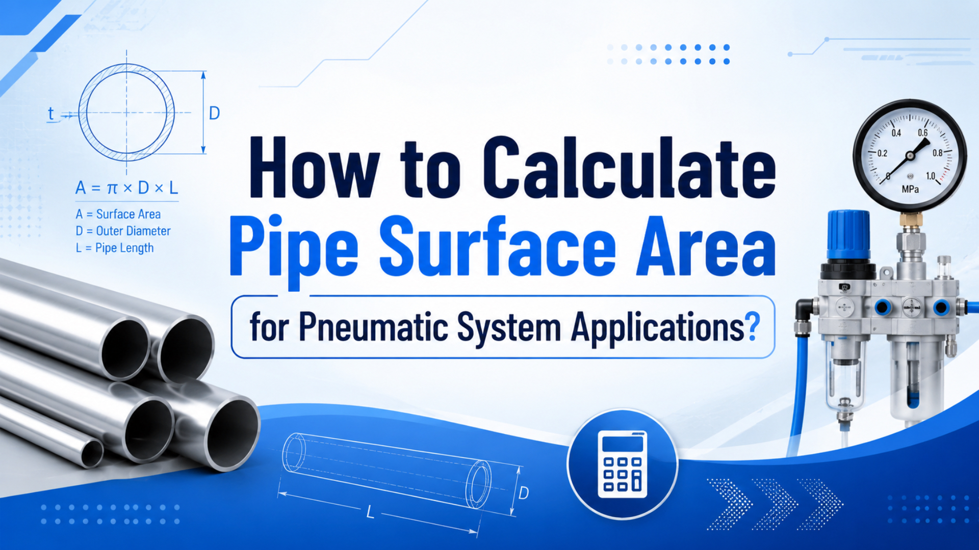
Pipe surface area in pneumatic systems is calculated from the circumference of the tube or pipe multiplied by its length. Use A = pi x D x L for outside surface area and A = pi x d x L for inside surface area, where D is outside diameter, d is inside diameter, and L is length.
That simple formula matters more than it first appears. Surface area affects coating coverage, heat exchange, inspection work, and the wall contact used in pressure-drop checks. CAGI says a well-designed compressed-air system should keep pressure drop between compressor discharge and point of use at no more than 10% (CAGI Pressure Drop Technical Brief, 2026). The tube route is part of that target.
Key Takeaways
- External pipe surface area is
pi x outside diameter x length; a 12 mm OD, 2 m tube has about 0.0754 m^2 of outside surface.- Internal surface area uses inside diameter, while flow area uses the bore cross-section. Don’t mix them.
- CAGI’s 10% pressure-drop target makes tube length, fittings, inside diameter, and surface condition part of pneumatic performance.
The quiet mistake is using “pipe size” as if it always means the same diameter. Push-to-connect pneumatic tubing is usually selected by outside diameter, while flow calculations care about inside diameter. Coating and heat checks use the outside. Pressure-drop and contamination checks care about the inside. Same tube, different surfaces.
What Is Pipe Surface Area in Pneumatic Systems?
Pipe surface area is the curved wall area of a tube or pipe, not the open flow area through the bore. CAGI’s 10% pressure-drop target is a useful reminder: the air path includes tubing, fittings, filters, regulators, valves, and point-of-use devices, not only the compressor (CAGI Pressure Drop Technical Brief, 2026).
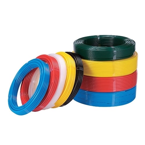
For pneumatic work, calculate three different areas:
| Area type | Formula | Diameter used | Common pneumatic use |
|---|---|---|---|
| External surface area | A = pi x D x L |
Outside diameter | Coating, corrosion checks, ambient heat exchange |
| Internal surface area | A = pi x d x L |
Inside diameter | Wall contact, contamination, internal inspection |
| Flow cross-section | A = pi x d^2 / 4 |
Inside diameter | Velocity, volume flow, pressure-drop inputs |
Surface area is a wall calculation. Flow area is a cross-section calculation. If a buyer sends only “8 mm tube,” ask whether that is OD tubing with a 6 mm ID, an 8 mm ID pipe, or a nominal pipe thread. That one clarification can change both the coating number and the pressure-drop estimate.
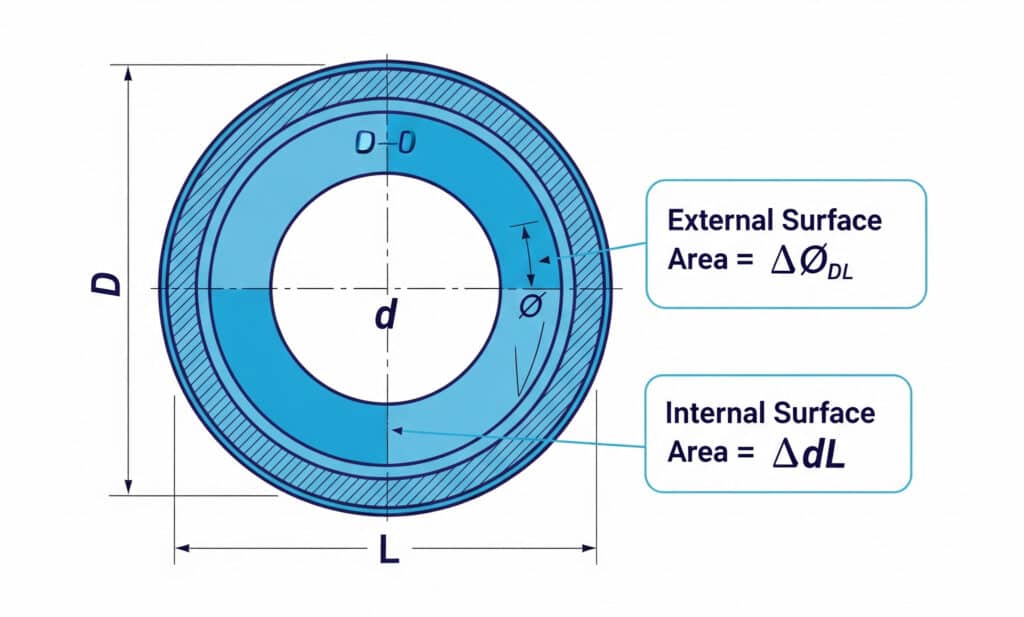
Surface Area Units
Keep every input in the same unit system before calculating. If diameter is in millimeters and length is in millimeters, the area comes out in mm^2. If diameter and length are in meters, the answer is in m^2.
External surface area = pi x outside diameter x length
Internal surface area = pi x inside diameter x length
Flow cross-section    = pi x inside diameter^2 / 4
For a 12 mm OD tube with a 2,000 mm length:
A = pi x 12 mm x 2,000 mm
A = 75,398 mm^2
A = 0.0754 m^2
That’s the outside wall area of the straight tube only. Add fittings, manifolds, elbows, and exposed threaded sections separately when coating, cleaning, or heat exchange matters.
Common Metric Tubing Examples
Festo’s tubing guide separates outside-diameter tubing from inside-diameter tubing, which is the same distinction engineers need for surface-area checks (Festo Guide to Pneumatic Tubing, 2024). The table below uses common metric OD sizes and one meter of straight tube.
| Tube OD | Outside circumference | External surface per 1 m | External surface per 1 m |
|---|---|---|---|
| 6 mm | 18.85 mm | 18,850 mm^2 | 188.5 cm^2 |
| 8 mm | 25.13 mm | 25,133 mm^2 | 251.3 cm^2 |
| 10 mm | 31.42 mm | 31,416 mm^2 | 314.2 cm^2 |
| 12 mm | 37.70 mm | 37,699 mm^2 | 377.0 cm^2 |
| 16 mm | 50.27 mm | 50,265 mm^2 | 502.7 cm^2 |
In our experience, most quoting mistakes happen at this table step. Someone calculates correctly in mm^2, then labels the converted answer as cm^2 without dividing by 100. The formula was right. The unit conversion did the damage.
How Do You Calculate External Pipe Surface Area?
External pipe surface area is the outside wall area that paint, insulation, corrosion, ambient air, clamps, and inspection tools touch. Pi Tape’s OD instruction sheet describes wrapping a diameter tape around a cylinder for direct outside-diameter reading, which is exactly the measurement you need before using A = pi x D x L (Pi Tape, 2026).
Use this workflow:
- Measure the outside diameter at more than one point.
- Measure the straight length or the actual curved centerline length.
- Put diameter and length in the same unit system.
- Calculate
pi x D x L. - Add separate surface allowances for fittings, bends, manifolds, or exposed threaded sections.
External Area Example for Coating
Suppose a pneumatic distribution branch uses these straight sections:
| Section | Outside diameter | Length | External surface |
|---|---|---|---|
| Main feed | 16 mm | 10 m | 0.503 m^2 |
| Branch tubing | 12 mm | 15 m | 0.565 m^2 |
| Control tubing | 8 mm | 5 m | 0.126 m^2 |
| Total straight tube | - | 30 m | 1.194 m^2 |
If the coating supplier gives coverage in m^2/L, this total is the first number. Then add waste, fittings, overspray, and surface preparation losses. Don’t pretend the straight-tube number covers every connector in the system.
NPT and Nominal Pipe Sizes
Nominal pipe size is a trade designation, not a guaranteed measured outside diameter. ASME says B1.20.1 covers dimensions and gauging for common inch pipe threads including NPT, NPSC, NPTR, NPSM, and NPSL (ASME B1.20.1, 2013). For threaded pipe or adapters, use the actual measured outside diameter or the standard’s dimensional table, not the trade name alone.
That point matters when a pneumatic drawing mixes push-to-connect metric tube, NPT ports, and BSP or metric adapters. A surface-area calculation based on label text can be wrong before the math starts.
Internal Surface Area vs Flow Area
Internal pipe surface area is the bore-wall area that touches compressed air; flow cross-section is the open area that air passes through. Britannica describes Reynolds number as a criterion for laminar or turbulent flow, with pipe flow commonly becoming turbulent above roughly 2,000 in simplified references (Britannica, 2026). That flow behavior depends on bore diameter, velocity, density, and viscosity, not outside coating area.
Use internal surface area when you care about:
- Oil film and particle deposition.
- Cleaning or flushing work.
- Bore inspection and corrosion contact.
- Heat transfer between air and tube wall.
- Wall contact in friction and roughness discussions.
Use flow cross-section when you care about:
- Air velocity.
- Cylinder fill time.
- Flow capacity.
- Pressure-drop inputs.
- Chamber refill and exhaust timing.
Internal Area Example
For a tube with 12 mm OD, 8 mm ID, and 2 m length:
External surface = pi x 12 mm x 2,000 mm = 75,398 mm^2 = 0.0754 m^2
Internal surface = pi x 8 mm x 2,000 mm  = 50,265 mm^2 = 0.0503 m^2
Flow area        = pi x 8^2 / 4            = 50.3 mm^2
Those three values answer different questions. The first is outside wall coverage. The second is internal wall contact. The third is the open bore area used for velocity and flow checks.
| Tube description | External surface per 1 m | Internal surface per 1 m | Internal surface difference |
|---|---|---|---|
| 10 mm OD, 8 mm ID | 0.0314 m^2 | 0.0251 m^2 | 20% lower |
| 12 mm OD, 8 mm ID | 0.0377 m^2 | 0.0251 m^2 | 33% lower |
| 16 mm OD, 12 mm ID | 0.0503 m^2 | 0.0377 m^2 | 25% lower |
When a tube gets thicker, the outside surface might stay attractive for mounting or durability, but the inside surface and flow area can shrink. That is why a mechanically stronger tube can still be a worse air path if the bore is too small for the actuator cycle.
Where Does Surface Area Affect Pressure Drop and Heat?
Surface area does not replace pressure-drop formulas, but it helps explain wall contact, heat exchange, inspection effort, and why long small-bore tubes punish fast pneumatic axes. DOE says every 2 psi pressure increase near 100 psig can raise energy use by about 1.6-2% when unregulated demand is 30-50% (DOE Sourcebook, 2016).
In other words, a surface-area mistake can become an energy mistake. If a small tube causes avoidable pressure drop, the usual reaction is to raise header pressure. That can make every leak and unregulated end use more expensive.
Pressure Drop and Surface Condition
The internal wall condition matters because moving air loses pressure as it passes restrictions, rough surfaces, undersized fittings, and long runs. CAGI recommends reducing pressure drop with adequate pipe sizing, minimum practical hose length, smooth-bore pipe where appropriate, and attention to velocity and restrictions (CAGI Pressure Drop Technical Brief, 2026).
For an engineering first pass, separate four checks:
| Check | What to calculate | What to inspect |
|---|---|---|
| Surface area | pi x d x L or pi x D x L |
Bore wall, outside wall, coating surface |
| Flow area | pi x d^2 / 4 |
Bore size and velocity |
| Equivalent length | Straight length plus fitting effects | Elbows, tees, couplers, valve bodies |
| Pressure profile | Upstream and downstream pressure under flow | Filters, regulators, valves, long tubes |
Need a quick internal link path for deeper troubleshooting? This companion article on pressure fluctuations in pneumatic systems explains why local point-of-use pressure can differ from the compressor-room gauge during a machine cycle.
Heat Transfer and Coating
For heat transfer, external surface area is the boundary exposed to ambient air. Internal surface area is the boundary exposed to compressed air. The classic heat-transfer relationship is:
Q = h x A x delta TA is the surface area in that equation. If a tube route overheats, surface area is one variable, but airflow, material, wall thickness, ambient temperature, enclosure ventilation, and compressor discharge temperature all matter too.
For coating, use external surface area plus allowances. A straight 30 m route may calculate to 1.194 m^2, but the real coating job includes fittings, brackets, threaded adapters, cleaning waste, overspray, and a second coat if the coating system requires it.
Field Measurement Workflow for Tubing and Pipe
Measure the tube before calculating when the part is already installed, and use the manufacturer’s data when the part is still in design. ENERGY STAR says compressed-air leaks often waste 20-30% of compressor output and can cause fluctuating system pressure, so field checks should combine dimensions, pressure, and leak review rather than treating surface area as a desk-only calculation (ENERGY STAR, 2000).
Start with a small worksheet:
| Field | Example entry | Why it matters |
|---|---|---|
| Tube or pipe label | 12 mm OD PU tube | Prevents nominal-size confusion |
| Measured OD | 12.0 mm | External surface and fitting fit |
| Measured ID | 8.0 mm | Internal surface and flow area |
| Straight length | 2.0 m | Surface area and volume |
| Fittings | 2 elbows, 1 tee, 2 push fittings | Equivalent length and restriction |
| Pressure under flow | 6.0 bar inlet, 5.4 bar actuator port | Real pressure drop |
| Condition | Clean, kinked, oily, corroded | Surface condition and maintenance |
What to Measure First
- Measure outside diameter with calipers or an OD tape.
- Confirm inside diameter from the tube datasheet or a clean cut end.
- Measure the actual route length, including curves.
- Record fittings and sharp bends separately.
- Measure pressure at the actuator port during motion, not only at the regulator.
- Check whether the FRL unit, pressure regulator, solenoid valve, or flow-control fitting is the real restriction.
For replacement work, link the calculation to the component choice. Short, clean polyurethane tubing can support a fast axis better than a longer, smaller, kinked route with the same nominal label. If the actuator still moves slowly after the surface-area and pressure checks, review cylinder force and air path together in pneumatic cylinder power troubleshooting.
Mistakes to Avoid
- Using radius where the formula asks for diameter.
- Mixing millimeters and meters inside one formula.
- Reporting
mm^2ascm^2. - Using outside diameter for internal flow area.
- Treating nominal NPT size as measured outside diameter.
- Ignoring fittings when estimating coating or pressure drop.
- Measuring pressure with the machine idle instead of under demand.
NIST lists 1 psi = 6,894.757 Pa, which is a useful reminder to convert pressure units deliberately when pneumatic drawings mix bar, MPa, psi, and Pa (NIST, 2025). Unit discipline is not paperwork. It is how you stop a small arithmetic error from becoming a wrong tube order.
FAQ: Pipe Surface Area in Pneumatic Systems
The questions below cover the five mistakes that most often create wrong pipe surface area calculations. DOE’s sourcebook shows why those mistakes matter economically: every 2 psi pressure increase near 100 psig can add about 1.6-2% energy use under common unregulated-demand conditions (DOE Sourcebook, 2016).
How do you calculate pipe surface area?
Calculate curved pipe surface area as circumference times length. For external surface area, use A = pi x D x L, where D is outside diameter. For internal surface area, use A = pi x d x L, where d is inside diameter. Keep diameter and length in the same units.
What is the difference between internal and external pipe surface area?
External surface area uses outside diameter and supports coating, corrosion, inspection, and ambient heat-transfer checks. Internal surface area uses inside diameter and describes the bore wall in contact with compressed air. A 12 mm OD, 8 mm ID tube has 33% less internal surface than external surface for the same length.
Is pipe surface area the same as flow area?
No. Pipe surface area is the curved wall area, calculated as pi x d x L or pi x D x L. Flow area is the open cross-section, calculated as pi x d^2 / 4. Use flow area for velocity and flow calculations, not coating coverage.
Why does pipe surface area matter in pneumatic systems?
Surface area affects coating quantity, heat exchange, contamination contact, inspection effort, and the wall condition behind pressure-drop concerns. CAGI recommends no more than 10% pressure drop from compressor discharge to point of use, so tube length, bore size, and restrictions deserve measurement.
What tools should I use to measure pipe surface area inputs?
Use calipers for small OD measurements, an OD tape for larger cylinders, datasheets for inside diameter, and a tape or CAD route length for installed runs. Then verify pressure under flow. The surface-area answer is stronger when it is tied to actual tube length, fittings, and operating pressure.
Sources
- CAGI: Technical Brief on Pressure Drop, compressed-air pressure-drop target and air-path guidance. Retrieved 2026-06-03.
- DOE: Improving Compressed Air System Performance, Third Edition, pressure increase energy impact, pressure-drop guidance, and system troubleshooting context. Retrieved 2026-06-03.
- ENERGY STAR: Minimize Compressed Air Leaks, leak waste range and fluctuating pressure effects. Retrieved 2026-06-03.
- NIST: Pressure and Gas Flow Unit Conversions, pressure conversion factor for psi to pascal. Retrieved 2026-06-03.
- ASME B1.20.1: Pipe Threads, General Purpose, Inch, NPT and related pipe-thread standard scope. Retrieved 2026-06-03.
- Pi Tape: Outside Diameter Tape Instructions, direct outside-diameter tape measurement method. Retrieved 2026-06-03.
- Festo: Guide to Pneumatic Tubing, outside-diameter and inside-diameter tubing distinction in pneumatic tubing references. Retrieved 2026-06-03.
- Britannica: Reynolds Number, flow-regime reference for laminar and turbulent pipe flow. Retrieved 2026-06-03.
- AutomationDirect video: Push-to-Connect Pneumatic Fittings, video transcript and YouTube-backed embedded video. Retrieved 2026-06-03. .