

Rod area is the circular cross-sectional area of a pneumatic cylinder piston rod. In a double-acting cylinder, that area must be subtracted from the piston area on the retract stroke, because compressed air cannot act on the part of the piston face covered by the rod.
The calculation is simple. The mistake is usually in the units. A 20 mm rod has a rod area of 314.2 mm^2, and 6 bar equals 0.6 N/mm^2, not 6 N/mm^2. Miss that conversion and the force result becomes 10 times too high.
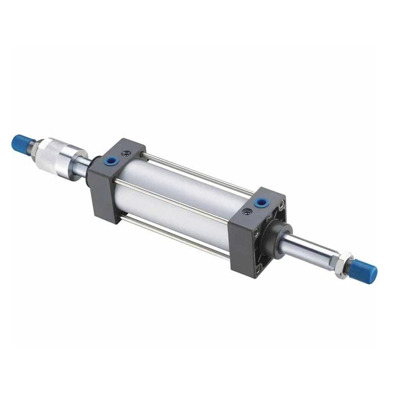
SCSU Series pneumatic tie-rod cylinders show the common single-rod layout used in many force and speed calculations. For related sizing context, see the SCSU standard cylinder and MB Series ISO 15552 tie-rod cylinder pages.
Key Takeaways
- Rod area is
A_rod = pi x (d / 2)^2orpi x d^2 / 4.- At 6 bar, use
0.6 N/mm^2; a 63 mm bore with a 20 mm rod produces about 1,870 N extend force and 1,682 N retract force before losses.- Rod area reduces retract force, reduces retract-side air volume, and usually makes the retract stroke faster at the same actual flow.
The fastest field check is this: calculate the rod-to-bore ratio, square it, and you already know the retract-force percentage lost to rod area. A 20 mm rod in a 63 mm bore loses about (20 / 63)^2 = 10.1% of piston area on the rod side.
Table of Contents
- What is Rod Area in Pneumatic Cylinder Systems?
- Rod Area Formula and Unit Checks
- How Do You Calculate Rod Cross-Sectional Area?
- Why Does Rod Area Change Retract Force?
- Rod Area Effects on Speed and Air Volume
- When Should Rod Area Drive Cylinder Selection?
- FAQs About Rod Area
What is Rod Area in Pneumatic Cylinder Systems?
Rod area is the round piston-rod cross-section used in rod-side force calculations. ISO 15552:2018 covers detachable-mounting pneumatic cylinders with bores from 32 mm to 320 mm and a maximum rated pressure of 1,000 kPa, or 10 bar (ISO 15552:2018, confirmed 2025).
In a standard pneumatic cylinder, the rod passes through one end cap and attaches to the piston. During extension, compressed air acts on the full piston face. During retraction, compressed air acts on the rod side, where the rod occupies part of the circular piston face.
That missing part is the rod area. It is not a correction factor. It is actual steel sitting where air would otherwise push. If the application depends on pull force, return speed, clamping release, or vertical retract motion, the rod area belongs in the first sizing pass.
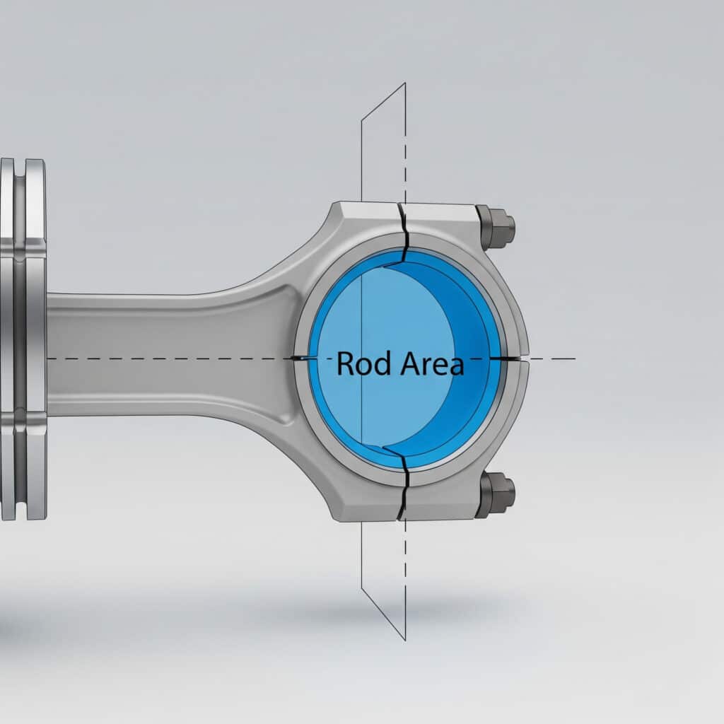
Rod area is measured perpendicular to the rod centerline. Use the rod diameter, not the stroke length, thread length, or chrome-plated outside appearance.
Rod Area Definition
| Term | Meaning | Formula |
|---|---|---|
| Bore area | Full piston face area | A_piston = pi x D^2 / 4 |
| Rod area | Circular piston-rod cross-section | A_rod = pi x d^2 / 4 |
| Rod-side effective area | Piston area minus rod area | A_retract = A_piston - A_rod |
| Rod-to-bore area loss | Retract area lost as a percentage | (d / D)^2 x 100% |
Here D is bore diameter and d is rod diameter. Keep them in the same unit. If bore is in millimeters, rod diameter must also be in millimeters.
The retract-side shape is an annulus: a ring made by subtracting the rod circle from the bore circle. MathWorld gives annulus area as the difference between two concentric circular areas, which is the same geometry behind pi x (D^2 - d^2) / 4 for the rod side (MathWorld, “Annulus”, accessed 2026).
Where Rod Area Matters
Rod area affects:
- Retract force in single-rod double-acting cylinders.
- Retract-side air volume and speed.
- Force balance between extend and retract strokes.
- Back-pressure calculations when exhaust restriction is present.
- Replacement checks when changing rod diameter, cylinder family, or standard.
It does not affect a rodless cylinder in the same way, because there is no external piston rod occupying one side of the piston face. If the application is long-stroke and retract force is becoming awkward, a rodless cylinder may be worth comparing.
Rod Area Formula and Unit Checks
Use A_rod = pi x d^2 / 4 with d in millimeters when you want area in mm^2. MathWorld gives the circle area as pi r^2, and NIST defines one bar as 100 kPa, or 100,000 pascals, so 1 bar equals 0.1 N/mm^2 (MathWorld, “Circle”, accessed 2026; NIST, 2022).
That conversion is where many bad pneumatic force tables go wrong. Pressure in bar cannot be multiplied directly by area in mm^2 unless you first convert bar to N/mm^2.
1 bar = 100,000 Pa
1 Pa = 1 N/m^2
1 N/mm^2 = 1,000,000 Pa
Therefore: 1 bar = 0.1 N/mm^2
Therefore: 6 bar = 0.6 N/mm^2
Where does the 10x error enter? It usually appears when someone writes 6 x 3,117 mm^2 = 18,702 N for a 63 mm bore at 6 bar. The pressure value should be 0.6 N/mm^2, so the theoretical extend force is about 1,870 N, before friction, back pressure, and acceleration allowances.
Standard Rod Area Table
| Rod diameter | Radius | Rod area |
|---|---|---|
| 8 mm | 4 mm | 50.3 mm^2 |
| 12 mm | 6 mm | 113.1 mm^2 |
| 16 mm | 8 mm | 201.1 mm^2 |
| 20 mm | 10 mm | 314.2 mm^2 |
| 25 mm | 12.5 mm | 490.9 mm^2 |
| 32 mm | 16 mm | 804.2 mm^2 |
These values come straight from the circular area formula. They are not catalog ratings. Catalog force can be lower after seal friction, guide friction, cushion settings, pressure drop, side loading, and exhaust back pressure.
In our experience, the most useful shop-floor habit is writing pressure in N/mm^2 beside every metric force calculation. It keeps the engineer, buyer, and maintenance technician from mixing bar, kPa, and mm^2 inside the same line.
How Do You Calculate Rod Cross-Sectional Area?
For a 20 mm rod, rod area is pi x 20^2 / 4 = 314.2 mm^2. MathWorld’s circle formula supports the same result through pi r^2, where r = 10 mm; both routes produce the same area when the diameter and radius are used correctly (MathWorld, “Circle”, accessed 2026).
Use this process:
- Measure the rod diameter with calipers.
- Divide by 2 if using the radius formula.
- Square the radius, or square the diameter and divide by 4.
- Multiply by
pi. - Keep the area unit squared.
Worked Example: 20 mm Rod
d = 20 mm
r = d / 2 = 10 mm
A_rod = pi x r^2
A_rod = 3.14159 x 10^2
A_rod = 314.2 mm^2
The diameter form gives the same result:
A_rod = pi x d^2 / 4
A_rod = 3.14159 x 20^2 / 4
A_rod = 314.2 mm^2
Common Measurement Errors
| Error | What happens | Fix |
|---|---|---|
Using diameter in pi r^2 |
Area becomes 4x too high | Use r = d / 2, or use pi d^2 / 4 |
| Mixing inch and metric units | Force output becomes meaningless | Convert before calculating |
| Using thread diameter | Rod area may be understated | Measure the main rod diameter |
| Rounding too early | Small rods get avoidable error | Keep at least one decimal place |
Use a micrometer when tolerance matters. For most application sizing, a clean caliper reading is enough, but measure more than one point if the rod is worn, damaged, or replated.
Why Does Rod Area Change Retract Force?
Rod area changes retract force because the rod-side effective area is smaller than full piston area. Parker states that the net area on a single-end-rod cylinder is full piston area minus rod area, and Engineering ToolBox gives the double-acting instroke formula F = p x pi x (d1^2 - d2^2) / 4 (Parker, accessed 2026; Engineering ToolBox, accessed 2026).
The force formulas are:
Extend force = pressure x piston area
Retract force = pressure x (piston area - rod area)
For a 63 mm bore with a 20 mm rod:
A_piston = pi x 63^2 / 4 = 3,117.2 mm^2
A_rod = pi x 20^2 / 4 = 314.2 mm^2
A_retract = 3,117.2 - 314.2 = 2,803.0 mm^2
At 6 bar:
Pressure = 0.6 N/mm^2
Extend force = 0.6 x 3,117.2 = 1,870 N
Retract force = 0.6 x 2,803.0 = 1,682 N
Difference = 188 N
Area loss = 10.1%This is why return-stroke problems can appear even when the extend stroke looks strong. A clamp may close cleanly but release poorly. A vertical axis may lift but struggle to retract under load. A pusher may move forward with margin and then stall on the way home.
For a broader force discussion, read calculating force from pressure and area in pneumatic systems.
Rod Area Effects on Speed and Air Volume
Rod area also changes speed and air volume because volumetric flow rate is volume per unit time, and flow across area relates to velocity. In a simple actual-flow calculation, 100 L/min equals 1,666,667 mm^3/s; divided by 3,117 mm^2 gives 535 mm/s on extension (Volumetric flow rate, accessed 2026).
That same actual flow into the smaller rod-side effective area gives a higher theoretical retract speed:
Q_actual = 100 L/min = 1,666,667 mm^3/s
Extend speed = 1,666,667 / 3,117.2 = 535 mm/s
Retract speed = 1,666,667 / 2,803.0 = 595 mm/s
Speed ratio = 1.11x
That number is a first-pass estimate, not a promise. Pneumatic catalogs often discuss standard flow, valve Cv, tube losses, exhaust restriction, regulator droop, cushion needles, and load dynamics. If you compare speed from a flow meter, make sure you know whether the reading is standard flow or actual chamber flow.
Rod-to-Bore Ratio Effects
For a single-rod cylinder, the area loss from rod area is simply (d / D)^2. The retract speed multiplier at equal actual flow is approximately 1 / (1 - (d / D)^2).
| Rod-to-bore ratio | Retract area loss | Approx. retract speed multiplier |
|---|---|---|
| 0.30 | 9% | 1.10x |
| 0.40 | 16% | 1.19x |
| 0.50 | 25% | 1.33x |
| 0.60 | 36% | 1.56x |
So should you always choose a smaller rod? No. Smaller rod area improves retract force symmetry, but the rod still has to survive buckling, bending, side load, and thread loading. If a long horizontal stroke is bending rods, the problem may be guidance or actuator architecture, not force math. See piston rod deflection calculations for the structural side.
When Should Rod Area Drive Cylinder Selection?
Rod area should drive selection when the retract stroke carries load, sets cycle time, or controls a safety-related return motion. ISO 15552’s current standard scope confirms that standard pneumatic cylinder dimensions are built around interchangeability, but the force calculation still depends on bore, rod diameter, pressure, and effective area (ISO 15552:2018, confirmed 2025).
Check rod area early in these cases:
- The cylinder pulls a load instead of only pushing it.
- The return stroke must meet a cycle-time target.
- The cylinder retracts against gravity, spring force, or tooling friction.
- The rod diameter changes during a replacement quote.
- The machine uses a pressure regulator below plant-line pressure.
- Exhaust flow is restricted by fittings, silencers, long tubes, or flow controls.
Selection Checklist
Use this sequence before ordering:
- Define the critical stroke direction: extend, retract, or both.
- Calculate piston area and rod area.
- Convert pressure to the correct force unit.
- Calculate theoretical extend and retract force.
- Apply allowances for friction, back pressure, acceleration, and safety margin.
- Check rod buckling and side-load risk.
- Verify mount, stroke, sensor, cushion, and port requirements.
If the job is a replacement, ask for bore, rod diameter, stroke, mounting style, thread, operating pressure, and photos of both cylinder ends. That gives a buyer enough information to compare like for like instead of replacing a failed cylinder with a visually similar part that pulls weaker on the return stroke.
A good RFQ does not only ask “what bore?” It asks “which direction is the loaded stroke?” That one question catches many undersized retract strokes before purchasing sends the drawing.
For more formula context, see how to calculate pneumatic cylinder theoretical force and what the cylinder formula means for pneumatic systems.
FAQs About Rod Area
How do you calculate rod area?
Calculate rod area with A_rod = pi x (d / 2)^2, where d is rod diameter. For a 20 mm rod, A_rod = pi x 10^2 = 314.2 mm^2. The same result comes from pi x d^2 / 4.
Why is rod area important in pneumatic cylinders?
Rod area is important because it reduces the effective area on the rod side of a single-rod double-acting cylinder. Parker notes that rod-side net area is full piston area minus rod area, so retract force is lower than extend force at the same pressure.
How does rod area affect cylinder force?
Rod area reduces retract force by reducing the pressure-acting area. A 63 mm bore with a 20 mm rod loses 314.2 mm^2 from the retract side, leaving 2,803.0 mm^2. At 6 bar, theoretical retract force is about 1,682 N.
What happens if you ignore rod area?
Ignoring rod area overstates retract force, understates retract speed differences, and can hide return-stroke failures. The error gets larger as rod-to-bore ratio increases. A 0.50 rod-to-bore ratio removes 25% of the retract-side area.
Does rod area affect cylinder speed?
Yes. At equal actual flow, the retract stroke is usually faster because the rod-side chamber has less effective area and less volume to fill. A 63 mm bore with a 20 mm rod has an estimated retract speed about 1.11 times the extend speed under the same actual-flow assumption.
Sources
- Wolfram MathWorld, “Circle”, https://mathworld.wolfram.com/Circle.html. Retrieved 2026-06-03. Supports circle area formula
A = pi r^2. - Wolfram MathWorld, “Annulus”, https://mathworld.wolfram.com/Annulus.html. Retrieved 2026-06-03. Supports annular-area reasoning for rod-side effective area.
- NIST, “Under Pressure: Blaise Pascal, the Barometer and Bike Tires”, https://www.nist.gov/blogs/taking-measure/under-pressure-blaise-pascal-barometer-and-bike-tires. Retrieved 2026-06-03. Supports 1 bar = 100 kPa = 100,000 Pa and Pa as SI pressure unit.
- ISO, “ISO 15552:2018 Pneumatic fluid power”, https://www.iso.org/cms/%20render/live/en/sites/isoorg/contents/data/standard/06/69/66921.html. Retrieved 2026-06-03. Supports standard-cylinder bore range, 1,000 kPa pressure series, and 2025 confirmation.
- Engineering ToolBox, “Pneumatic Cylinder - Exerted Force vs. Pressure”, https://www.engineeringtoolbox.com/pneumatic-cylinder-force-d_1273.html. Retrieved 2026-06-03. Supports double-acting instroke formula using bore diameter minus rod diameter.
- Parker Hannifin, “Designing With Cylinders”, https://www.parker.com/parkerimages/mobilecylinder/cat/english/0001q.pdf. Retrieved 2026-06-03. Supports single-end-rod net area and lower retraction force.
- Wikipedia, “Volumetric flow rate”, https://en.wikipedia.org/wiki/Volumetric_flow_rate. Retrieved 2026-06-03. Supports flow as volume per unit time and flow-area-velocity reasoning.