

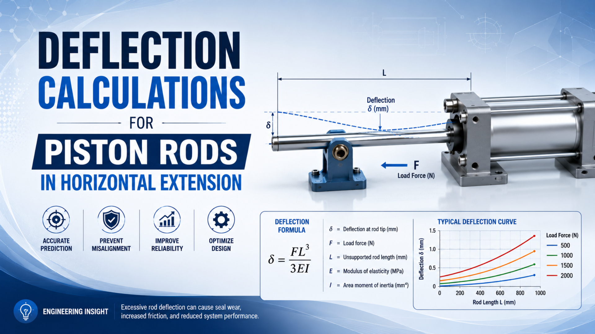
Calculate a horizontally extended piston rod only after separating transverse tip load, rod self-weight, and axial thrust. A tip force uses the cantilever term , while rod self-weight is a distributed load and uses . Mixing those loads in one equation can understate deflection and hide a poor load path.
This is a screening calculation, not a cylinder rating. The real assembly also includes rod-bearing clearance, gland compliance, mounting movement, rod-end geometry, external guides, and the machine frame. Compare the calculation with the selected cylinder’s lateral-load data and the machine’s permitted tool-point displacement.
Key Takeaways
- Tip load and rod self-weight require different beam equations.
- A 25 mm rod, 800 mm span, and 150 kg transverse tip load produces a linear estimate near 66 mm, not 6.7 mm.
- Buckling is an axial stability check, not a lateral-deflection calculation.
- Manufacturer load limits outrank a generic millimetres-per-metre rule.
What Does Horizontal Piston-Rod Deflection Mean?
Festo’s current DSBC catalogue tells users to support certain piston-rod configurations when transverse force is present or stroke exceeds 500 mm. That is a product-specific instruction, not a universal stroke limit (Festo DSBC catalogue, 2026). Horizontal piston-rod deflection is elastic movement perpendicular to the rod axis under a defined load.
A cylinder mounted horizontally doesn’t automatically carry the payload’s full weight through its piston rod. If a conveyor, linear rail, slide, or machine bearing supports the payload, the rod should mainly transmit axial thrust. Payload weight enters the rod-deflection calculation only when the rod or rod-end attachment actually carries a transverse reaction.
Use these definitions:
- Axial force acts along the rod centreline and belongs in force and compression-buckling checks.
- Transverse force acts perpendicular to the rod and creates bending.
- Distributed self-weight acts along the exposed rod rather than at one point.
- Offset load creates a force plus a moment because its centre of gravity is away from the rod joint.
- Dynamic transverse load comes from acceleration, deceleration, vibration, hose pull, linkage reactions, or impact.
The first calculation is therefore a load-path decision: does the rod carry the weight, or does a guide carry it? A beam equation cannot repair an incorrect free-body diagram. The side-loading failure guide covers the wear patterns caused when transverse reactions reach the rod bearing, seal, and piston.
For the broader fixed-beam assumptions, measurement method, and control hierarchy, use the cantilevered cylinder-deflection guide. This article stays narrower by separating horizontal rod self-weight from a true transverse point load.
Which Loads Belong in the Deflection Calculation?
NASA lists five core assumptions for classical beam modelling, including a slender beam, small deflection, an unstretched centreline, rigid cross-sections, and negligible transverse shear (NASA beam-mechanics reference, 2019). Before applying that model, locate the effective support and the real point where each transverse force enters the assembly.
Unsupported length is the distance from the effective lateral support to the point where the transverse load enters the rod assembly. Draw the mechanism at its worst horizontal extension and record:
- Exposed rod length from the effective support to the rod-end joint.
- Additional adapter, clevis, or tooling overhang to the transverse load point.
- Payload centre-of-gravity offset from the rod axis.
- Guide reactions and whether they remove payload weight from the rod.
- Acceleration and deceleration forces at their actual offsets.
- Hose, cable, linkage, belt, and process reactions.
- Axial compression that requires a separate buckling check.
Nominal stroke is not automatically the unsupported length. A long rod-end adapter can increase the lever arm beyond the stroke, while a properly located guide can shorten the structural span. The stroke-position and cantilever-load article explains why full extension changes mechanical risk without directly reducing pressure-generated axial force.
Don’t enter the complete payload mass as a transverse load merely because the cylinder is horizontal. Convert a supported payload into the reactions actually reaching the rod joint. If those reactions are unknown, measure them, calculate them from the guide geometry, or treat the load case as unresolved.
In our experience reviewing horizontal-cylinder applications, the fastest useful check is a free-body sketch with separate axial and transverse arrows. It often exposes an unsupported offset, guide reaction, or adapter length before any equation is entered. That simple sketch also prevents the cylinder’s axial thrust from being counted as a bending load.
How Do Point Load and Rod Self-Weight Use Different Equations?
For NASA’s ideal clamped-free beam with a transverse tip load, free-end deflection varies with the cube of unsupported length. A uniformly distributed load is a different beam case and varies with the fourth power of length. Both relationships assume a prismatic, linearly elastic beam and an effective fixed support that approximates the real cylinder assembly.
For a solid circular piston rod, the second moment of area is:
Here, is the second moment of area and is the load-bearing rod diameter. Use the plain shank diameter for the beam segment being checked. A threaded section, hollow rod, stepped rod, or cross-drilled feature needs its actual local geometry.
The transverse tip-load contribution is:
Here, is transverse force, is unsupported length, and is Young’s modulus. The force must act at the stated tip location. An intermediate load uses a different expression.
Rod self-weight per unit length is:
The corresponding free-end deflection is:
When both loads act in the same direction and the linear assumptions remain valid:
If loads act in different planes, calculate vector components rather than adding magnitudes. Keep one unit system throughout. For example, using force in newtons, length in millimetres, in , and in returns deflection in millimetres.
How do you check bending stress?
Deflection is a stiffness result. Strength needs a separate check. For the same ideal load case, the maximum fixed-end moment is:
The nominal outer-fibre bending stress for a solid circular rod is:
Compare this nominal stress with the specified rod material, thread geometry, surface condition, fatigue duty, stress concentration, and the manufacturer’s allowable loading method. Chrome plating changes surface behaviour, but it does not turn a carbon-steel rod into a different bulk stiffness class.
What Does a Corrected 25 mm Rod Example Show?
Using a 25 mm solid steel rod, 800 mm unsupported length, , and a true 150 kg transverse tip load gives an ideal linear estimate near 66 mm. The calculated deflection is about 8.25% of the span, so the result should reject the load path rather than be treated as a precise operating prediction.
First calculate section properties and self-weight:
The 150 kg mass produces only if its full weight actually acts transversely at the rod end:
Rod self-weight adds:
The linear total is therefore about 65.99 mm, not 6.7 mm. The corresponding nominal small-deflection bending-stress calculation is about 775 MPa. Large displacement, bearing rotation, material yielding, and changing load direction can all invalidate the linear prediction before that theoretical shape is reached.
The result does not prove that every 150 kg conveyor application needs a larger cylinder. It proves that a 150 kg transverse tip load is an unsuitable assumption or an unsuitable architecture for this rod. If the conveyor supports the mass and only 50 N reaches the rod transversely, the same linear model gives about 2.23 mm from the tip force plus 0.50 mm from self-weight, or 2.73 mm total.
| Input or result | 150 kg transverse tip-load case | 50 N transverse-reaction case |
|---|---|---|
| Rod diameter | 25 mm | 25 mm |
| Unsupported length | 800 mm | 800 mm |
| Tip force | 1,471.5 N | 50 N |
| Tip-load deflection | 65.49 mm | 2.23 mm |
| Self-weight deflection | 0.50 mm | 0.50 mm |
| Linear total | 65.99 mm | 2.73 mm |
| Nominal bending stress | 775 MPa | 34.0 MPa |
| Engineering interpretation | Reject load path; linear result not precise | Continue with catalog and machine-limit checks |
Neither column is a cylinder rating. The table shows why the transverse reaction, not the payload nameplate mass, is the decisive input.
How Much Piston-Rod Deflection Is Acceptable?
Festo’s DSBC data gives a model-specific example of 9.5 N permissible lateral force for a 32 mm bore, 150 mm stroke, and 84 mm lever arm. Its limits change with bore, stroke, orientation, and configuration (Festo DSBC catalogue, 2026). There is no universal 0.5 mm-per-metre limit.
Check three different acceptance boundaries:
- Cylinder limit: allowable transverse force, moment, rod-end load, stroke, mounting, and configuration from the exact catalogue.
- Machine limit: permitted tool-point displacement, angular error, guide preload change, clearance, and repeatability.
- Service limit: acceptable seal wear, leakage, temperature, vibration, friction, and inspection interval.
SMC notes that guided-cylinder deflection and load capacity vary by model and bore, while speed and overhang also change the result (SMC guided-cylinder selection guide). A calculated rod deflection below the process tolerance can still be unacceptable if the rod bearing or rod-end joint exceeds its rating.
ISO 15552 standardizes interchangeable dimensions for detachable-mounting pneumatic cylinders with bores from 32 to 320 mm and a maximum rated pressure of 1,000 kPa. It does not provide a universal side-load or deflection allowance (ISO 15552:2018, confirmed 2025).
Keep axial buckling separate. A rod can pass this lateral-deflection screen and still buckle while pushing in compression. Use the piston-rod buckling guide for effective length, end restraint, manufacturer charts, and compression margin.
Which Design Changes Reduce Horizontal Deflection?
Parker offers rod-guidance modules for 32 to 100 mm bores and standard strokes from 25 to 250 mm, with special strokes to 500 mm. A self-aligning fitting limits unwanted assembly stress (Parker P1D catalogue, accessed July 23, 2026). That architecture illustrates why load guidance comes before rod oversizing.
Use this order:
- Correct misalignment. Align the cylinder, rod joint, guide, and tooling through the full stroke.
- Move weight and moments into a guide. Let the guide carry transverse reactions while the cylinder provides thrust.
- Reduce the load-centre offset. Bring the payload centre of gravity closer to the guide or rod joint.
- Shorten the unsupported length. Move the support or load point closer when the motion architecture allows it.
- Reduce dynamic demand. Lower acceleration, end velocity, shock, or vibration that creates lateral force.
- Increase rod diameter. Recheck retract force, bearing, seal, thread, moving mass, and model availability.
- Change actuator architecture. Consider a guided cylinder or guided rodless actuator when the travel and envelope justify it.
A rodless cylinder removes the projecting piston rod, but it does not promise zero structural deflection. An unguided rodless cylinder may still need an external guide. A guided model must stay within its simultaneous force and moment ratings, support-spacing rules, speed limits, and allowable stopping energy. Compare those details in the rodless versus standard cylinder guide.
How Do You Measure Deflection on the Machine?
Parker requires piston-rod alignment checks in two positions, fully extended and fully retracted, because poor alignment accelerates rod-gland or cylinder-bore wear (Parker Cylinder Safety Guide, accessed July 23, 2026). Add loaded mid-stroke measurements when guides or brackets change compliance through travel.
Use a dial indicator, displacement sensor, or laser system at a documented measurement point. Record:
- machine state and safe isolation procedure;
- cylinder position and pressure state;
- payload and motion condition;
- measurement direction;
- reference surface or machine datum;
- unloaded and loaded readings;
- guide, bracket, and frame movement;
- repeatability across several cycles.
Measure tool-point displacement as well as rod movement. If the indicator references a bracket that bends with the cylinder, the reading can hide common movement. A second indicator on the cylinder body or guide helps separate rod contribution from mounting and frame compliance.
Do not force the rod sideways by hand while the cylinder is pressurized. Release or safely restrain stored pneumatic energy according to the machine’s risk-control procedure before touching joints, guides, or fixtures. Measurement identifies the displacement; it does not by itself establish the cylinder’s allowable load.
A Better Horizontal-Extension Review Workflow
ISO 15552 covers cylinder mounting interchangeability up to 1,000 kPa, while the exact manufacturer’s catalogue supplies the functional limits needed for selection. Record both the standardized interface and the application-specific loads (ISO 15552:2018, confirmed 2025). A complete review prevents one ideal beam result from becoming the entire design decision.
Use this worksheet before requesting a cylinder:
| Review item | Required input or evidence |
|---|---|
| Cylinder identity | Manufacturer, series, bore, rod diameter, stroke, variant |
| Mounting | Body mount, rod-end joint, pin axes, bracket stiffness |
| Unsupported geometry | Effective support to load point at each critical position |
| Transverse loading | Static force, direction, centre-of-gravity offset, external moment |
| Dynamic loading | Moving mass, acceleration, deceleration, vibration, impact |
| Guidance | Guide type, bearing spacing, preload, force and moment ratings |
| Beam inputs | Rod geometry, material modulus, load distribution, unit system |
| Separate stability check | Maximum axial compression and effective buckling length |
| Acceptance criteria | Catalogue limit, tool-point error, alignment, service condition |
| Validation | Extended, retracted, mid-stroke, loaded, and unloaded measurements |
If the design depends on a generic statement such as “horizontal strokes over 500 mm need a rodless cylinder,” the review isn’t finished. A short conventional cylinder can fail under a large offset reaction, while a longer rod cylinder can operate correctly when an external guide carries the transverse load and the rod remains within its published limits.
Horizontal Piston Rod Deflection FAQs
Festo’s 9.5 N worked lateral-force example and Parker’s two-position alignment requirement show why the common questions need model and geometry context. The answers below separate beam screening from cylinder selection, axial stability, material stiffness, and rodless guidance rather than relying on a universal stroke or deflection threshold.
Is piston-rod deflection the same as side load?
No. Side load is a transverse force or moment applied to the rod assembly; deflection is one resulting displacement. The same side load can produce different rod, bearing, guide, bracket, and frame movement depending on geometry and stiffness. Diagnose the complete load path before assigning all measured movement to the piston rod.
Should payload weight always be entered as the tip load?
Only when the rod-end assembly actually supports that weight transversely. A conveyor, guide rail, or carriage often carries gravity while the cylinder supplies axial thrust. Use the reaction transmitted into the rod joint, including any offset moment. Entering the complete payload weight can exaggerate deflection by orders of magnitude.
Is horizontal deflection the same as piston-rod buckling?
No. Horizontal bending comes from transverse force and distributed weight. Buckling is an instability caused by axial compression and depends on effective length and end restraint. A design can fail either check independently. Calculate both when a long extended rod pushes in compression, then compare each result with the manufacturer’s selection method.
Can a larger rod eliminate the need for an external guide?
Not automatically. A larger solid rod reduces ideal tip-load deflection strongly, but the rod bearing, seal, thread, mount, and tooling still receive the transverse reaction. External guidance is usually the better load path when the payload has meaningful weight, offset moment, or dynamic side force. Check the complete assembly, not diameter alone.
Does a rodless cylinder have zero deflection?
No. It eliminates the projecting piston rod, but its extrusion, carriage, bearings, guide, supports, tooling, and frame remain elastic. Unguided rodless cylinders may require a separate guide. For guided versions, check simultaneous force and moment ratings, support spacing, speed, and stopping energy for the exact model and stroke.
Sources and technical references
- NASA, Distributed Sensing of a Cantilever Beam and Plate Using a Fiber Optic Sensing System
- Festo, DSBC Standards-Based Cylinders
- SMC, Basic Characteristics of Cylinders with Guide
- Parker, Cylinder Safety Guide
- Parker, P1D Pneumatic Cylinders and Rod Guidance Modules
- ISO 15552:2018, Pneumatic Cylinders with Detachable Mountings
Conclusion: Calculate the Load Path Before Selecting the Rod
NASA’s ideal beam relation, Festo’s model-specific lateral-load data, and Parker’s two-position alignment check point to the same conclusion: a useful answer needs a defined transverse reaction, unsupported length, material, support condition, and acceptance limit. Separate rod self-weight from tip load, screen bending stress and buckling independently, then verify the exact assembly.
The most effective correction is often structural. Put payload weight and offset moments into a properly rated guide, leaving the cylinder to provide axial thrust. Increase rod diameter or change actuator architecture only after the force path, motion profile, mounting, and machine tolerance are documented.