

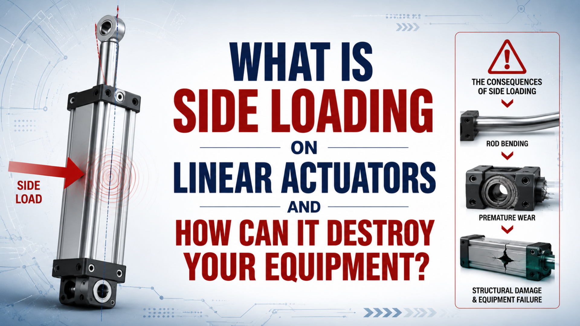
Side loading on a linear actuator is force applied perpendicular to its intended stroke axis. The force pushes a rod, bearing, seal, carriage, or guide away from its designed load path. Damage begins as uneven contact or structural deflection and can progress into scoring, leakage, binding, loose mounts, guide wear, and loss of repeatable motion. The dangerous number is not a universal percentage of actuator thrust. It is the configured product’s allowable transverse force and moment at the actual stroke, offset, orientation, speed, and mounting condition. A cylinder can have enough axial force to move the payload and still be overloaded laterally.
Key Takeaways
- Parker requires alignment checks in 2 positions: fully extended and fully retracted.
- Side-load capacity must come from the exact actuator or guide data, not a fixed percentage of thrust.
- Record wear direction, load offset, guide movement, and dynamic behavior before replacing seals or increasing pressure.
What Is Side Loading on a Linear Actuator?
SMC publishes rod-end side-load limits against the combined stroke and eccentric distance at 0.5 MPa for its CVQ compact cylinder, rather than as one percentage of axial thrust (SMC CVQ catalog, retrieved 2026-07-14). Side loading is therefore a model-and-geometry load case, not a generic rating.
Three different reactions are often grouped under the same label:
| Load type | Direction or effect | Component that should carry it |
|---|---|---|
| Axial force | Parallel to the stroke axis | Piston, rod, carrier, and centerline mounts |
| Transverse force | Perpendicular to the stroke axis | Rated rod bearing, guide, rail, or guided carriage |
| Moment | Rotation created by force acting through an offset | Guide spacing, carriage bearings, mount, and machine frame |
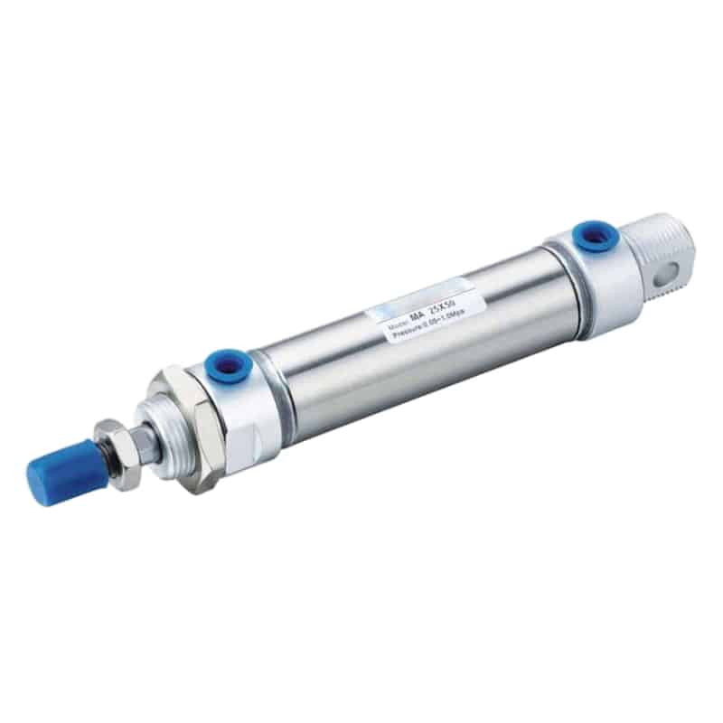
A standard rod cylinder is primarily a thrust device. Its rod bearing keeps the rod aligned and may tolerate a documented transverse load, but it should not be treated as a substitute for a linear rail. A guided actuator is different because its bearing architecture is intended to carry defined lateral forces or moments. Gravity can create a constant side load on a horizontal cylinder. Cable drag, hose reaction, an off-center gripper, an angled linkage, or a hard stop can add a load only at certain positions. The cylinder datasheet, guide coordinate system, and mounting drawing must describe the same geometry.
How Does Side Loading Destroy Rods, Bearings, and Seals?
Parker instructs users to check rod-to-machine alignment in 2 positions, fully extended and fully retracted, and states that improper alignment causes excessive rod-gland or cylinder-bore wear (Parker Pneumatic Actuator Safety Guide, retrieved 2026-07-14). Side loading destroys equipment by concentrating contact where the sliding system was not designed to carry it.
The damage chain usually develops in this order:
- The mounting geometry pushes the rod or carriage off its intended datum.
- Contact pressure then concentrates on one side of the bearing, bushing, seal, guide block, or tube instead of remaining within the intended load path.
- Friction and deflection rise.
- Wear particles, scoring, leakage, and lost clearance amplify the original misalignment as cycling continues.
- The machine may eventually bind, stop inconsistently, loosen fasteners, lose repeatability, or transmit damaging reactions into connected tooling and its mounting structure.
More supply pressure can hide the first symptom by forcing the axis through a tight spot. It also raises axial force against the same misaligned load path. If motion improves only after pressure is increased, verify alignment and guide resistance before accepting that pressure as the repair.
The most useful distinction is between force capacity and load-path compatibility. A 1,000 N cylinder does not become safe because the unwanted lateral force is small relative to 1,000 N. The permissible value may change with stroke, rod extension, eccentric distance, bearing type, speed, and mount stiffness.
Damage Patterns That Point to Side Loading
Parker’s safety guide calls for alignment checks at 2 end positions and links poor alignment to rod-gland and bore wear; its leakage guidance also directs attention to dents, gouges, and score marks on the rod (Parker Pneumatic Actuator Safety Guide, retrieved 2026-07-14). Side-load evidence is directional and position-dependent.
| Evidence | What it can indicate | What to measure next |
|---|---|---|
| Seal wear concentrated on one side | Rod or carriage is being pushed off center | Wear direction, load direction, rod alignment |
| Longitudinal rod scoring | High local bearing pressure or contamination dragged through a biased seal | Surface direction, guide resistance, bushing clearance |
| Smooth motion unloaded, binding under payload | Frame, rail, bracket, or mounting plate deflects | Indicator readings with and without load |
| Binding only near full extension | Moment rises with rod extension or structure loses support | Offset and clearance at retracted, mid-stroke, extended |
| Repeated loose bolts or shifted dowels | Mount is resisting a turning moment or impact | Fastener condition, frame stiffness, stop location |
| Seal replacement followed by rapid repeat leakage | Root load path was not corrected | Alignment, guide datum, coupling position, rod witness marks |
No single mark proves side loading. Contamination can score a rod, poor lubrication can raise guide friction, a damaged tube can create a tight spot, and incorrect cushion adjustment can produce impact. A diagnosis needs a pattern: where the damage appears, when the motion changes, and which direction the external load acts.
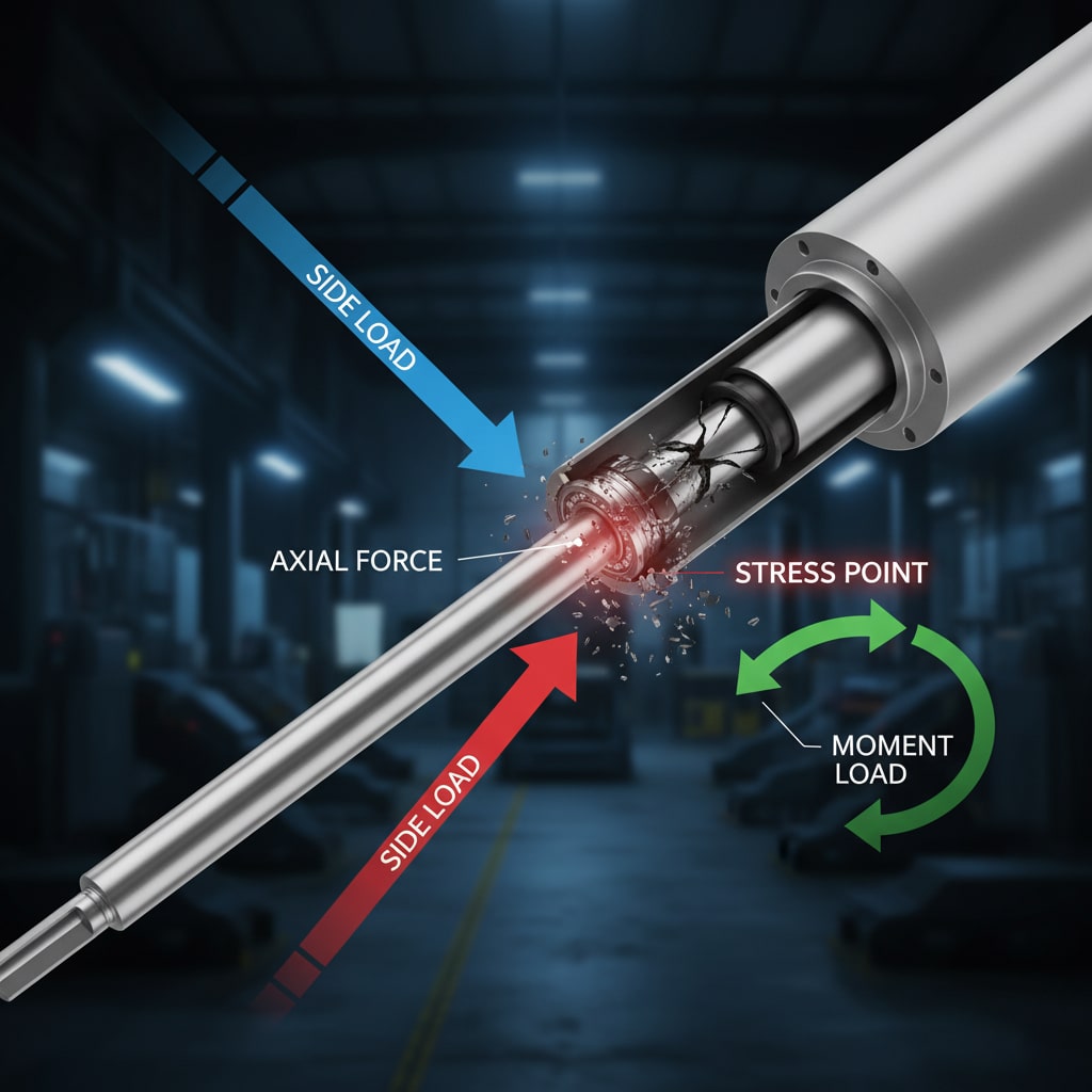
This is a qualitative load-path illustration. It does not show a permissible force, moment, or service-life value.
Why Does Offset Matter More Than Force Alone?
Parker calculates bending moment as M = F × l from the center of its OSP-P linear actuator and limits the cited load data to light, shock-free operation at speeds no greater than 0.5 m/s (Parker OSP-P catalog, retrieved 2026-07-14). Offset converts a transverse force into a larger bearing or guide demand.
M = F × l
Mis moment.Fis transverse force in newtons.lis the perpendicular distance from the selected bearing or carriage center to the force line; use metres with newtons to calculate N·m.
For example, a 100 N transverse force acting 0.20 m from the bearing center creates 20 N·m of moment. Moving the same load to 0.40 m doubles the moment to 40 N·m even though the force did not change. That is why a longer tooling plate can overload a guide without increasing payload mass.
The calculation does not finish with one moment. Guided rodless actuators may publish allowable forces in several directions and pitch, roll, and yaw moments. Use the supplier’s coordinate system, then check individual and combined limits. The rodless-cylinder load-capacity guide covers those multi-axis checks in more detail.
Static and Dynamic Side Loads Need Different Evidence
SMC’s C55 selection data separates allowable lateral load from kinetic-energy limits and relates the lateral-load graph to stroke plus eccentric distance at 1 MPa (SMC C55 catalog, retrieved 2026-07-14). Static geometry can be acceptable while acceleration, stopping, vibration, or pressure-driven impact creates an intermittent overload.
Static side loads are present while the axis is stopped. Typical sources include gravity, a misaligned fixed bracket, cable tension, a skewed rail, guide preload, or a load center that sits away from the supported plane. Look for persistent deflection, uneven clearances, and resistance that can be felt during permitted manual travel. Dynamic side loads appear or grow during motion. Common sources include payload inertia, an off-center stop, cushion entry, hose pull, a cam or linkage reaction, process contact, and a flexible frame that moves under acceleration. The evidence may disappear when the machine is depressurized or cycled without payload.
Compare the same position in three states: depressurized manual travel, low-speed powered travel, and normal production motion. Binding in all three points toward geometry or damaged bearings. A fault that appears only under powered load points toward deflection, pressure-dependent force, acceleration, stop energy, or a process reaction.
For end-of-stroke impact and deceleration, use the separate pneumatic-cylinder cushioning guide. Cushion capacity and side-load capacity are related through the load path, but they are not interchangeable ratings.
How Do You Diagnose the Complete Load Path?
Parker requires rod alignment to be checked at both the fully extended and fully retracted positions, a minimum of 2 geometry checks before blaming the seal or cylinder bore (Parker Pneumatic Actuator Safety Guide, retrieved 2026-07-14). Diagnose the actuator, guide, payload, mounting structure, joint, and stop as one mechanical chain.
Before hands enter the machine, apply the site’s validated energy-control procedure. OSHA 29 CFR 1910.147 covers servicing where unexpected startup or stored pneumatic, mechanical, electrical, or other energy could injure a worker (OSHA 1910.147, retrieved 2026-07-14).
Use this diagnostic sequence:
- Record the actuator and guide model numbers, mounting arrangement, stroke, payload, orientation, operating pressure, speed, and stop location before disturbing the assembly.
- Isolate energy, vent stored pressure, block gravity loads, and verify the safe state.
- Photograph the evidence.
- If the manufacturer and risk assessment permit it, disconnect the actuator from the payload, preserve the original alignment readings, and move the actuator and guided mechanism separately to identify which part resists travel.
- Check alignment and clearance at retracted, mid-stroke, and extended positions.
- Repeat indicator readings with the payload removed and installed.
- Mark gravity, process force, cable drag, hose reaction, acceleration, and stop force on one load-path sketch.
- Calculate each transverse force and moment, then compare them with the exact configured catalog limits.
- Restart only through the approved commissioning sequence, beginning with low energy and low speed in a clear motion zone before restoring the production payload and speed.
Never use mounting bolts to pull a cylinder and rail into alignment. That stores deflection in the structure and can make an unloaded axis appear straight while the bearing systems fight each other through the full stroke.
When Should You Realign, Add Guidance, or Replace the Actuator?
SMC’s MGQ guided-cylinder family spans 10 bore sizes from 12 to 100 mm and isolates load bearing from rod and seal motion through integrated guide shafts (SMC MGQ product data, retrieved 2026-07-14). Choose the corrective action from the failed load-path boundary, not from bore size alone.
| Finding | Corrective direction | Verification before release |
|---|---|---|
| Cylinder and guide are individually sound but their datums disagree | Realign mounts, rail, tooling, and connection | Indicator readings at 3 positions, unloaded and loaded |
| Payload or offset exceeds the basic cylinder’s documented lateral allowance | Add an external guide or select a rated guided actuator | Force and moment calculation against configured limits |
| Two rigid guides fight each other | Establish one primary datum and controlled compliance | Manual full-stroke travel without fasteners pulling parts into line |
| Rod, bushing, carriage, tube, or mounting surface is damaged | Replace or repair only under the manufacturer procedure | Surface, clearance, leakage, and repeatability checks |
| Impact created the side-load event | Move the stop, reduce speed, or add rated cushioning or shock absorption | Loaded stopping test at production conditions |
A rodless cylinder is not automatically immune. Basic rodless designs, internally guided carriages, and externally guided systems have different force and moment limits. Compare architectures with the rodless-versus-standard cylinder guide, then use the exact model data. For a retrofit workflow covering mounting families, flexible couplings, guide selection, and release testing, use the linear-cylinder side-load mitigation guide. This article’s diagnostic record should become the input to that engineering decision.
What Should You Record Before Restarting?
Lehigh reports a 100,000-cycle test on a 2-inch-bore JHD pneumatic cylinder with a built-in side load, illustrating that a result belongs to its test configuration (Lehigh Fluid Power video page, retrieved 2026-07-14). Your restart record must identify the actual geometry, payload, speed, pressure, and acceptance criteria used on the machine.
Record these items before and after correction:
- Identify the exact actuator and guide models.
- Note catalog revisions, mounting accessories, payload mass, center of gravity, transverse forces, measured offsets, and every calculated moment used for the acceptance decision.
- Save retracted, mid-stroke, and extended alignment readings under both unloaded and loaded conditions.
- Photograph directional wear on the rod, seal, guide tracks, fasteners, and stops before cleaning changes the evidence.
- Log pressure during motion, cycle time, speed, cushion setting, and the precise stroke position where binding begins.
- Preserve manual-travel findings, low-speed observations, and the final production-condition acceptance result with the name or identifier of the approved test procedure.
Write the failure as a boundary statement. “Cylinder failed” is too vague. For example: “The load plate moved 0.6 mm toward the cylinder at full payload, forcing the rod against the lower gland near full extension.” That identifies a measurable mechanism and tells the next engineer what must remain corrected. If the axis still needs more axial force after alignment is verified, review pressure-area fundamentals in the pneumatic-cylinder theory guide. Keep that axial-force question separate from the transverse-load and moment review.
FAQ
SMC’s MGQ range lists 10 bore sizes from 12 to 100 mm in the published catalog, yet its permissible lateral loads still vary with bearing type and stroke (SMC MGQ catalog, retrieved 2026-07-14). No single side-load percentage can answer every actuator application.
How much side loading can a linear actuator handle?
Use the exact model’s lateral-force and moment data. SMC’s MGQ tables vary allowable load by bore, stroke, and bearing type across 10 bore sizes, while other cylinders publish limits against stroke plus eccentric distance. A fixed percentage of axial thrust cannot replace those configured curves and combined-load rules.
Can a small side load still damage a cylinder?
Yes, especially when the force acts through a long offset or the mechanism is over-constrained. Parker uses M = F × l, so doubling the offset doubles the moment with the same transverse force. Compare that moment and every direct lateral force with the configured bearing, guide, and mounting limits.
Does rod scoring prove that side loading caused the failure?
No. Parker directs technicians to examine dents, gouges, and score marks during leakage diagnosis, but contamination and damaged surfaces can create similar evidence. Side loading becomes more likely when scoring direction, one-sided seal wear, position-dependent binding, guide deflection, and the external load direction agree with one load-path explanation.
Do rodless cylinders handle side loading better than rod cylinders?
Some guided rodless designs carry substantial forces and moments, but “rodless” alone is not a rating. Parker’s OSP-P data separates force and 3 moment axes, and each configuration has limits. Basic rodless cylinders may still need external guidance. Compare the exact carriage, guide, speed, offset, and combined-load rules.
Can higher air pressure fix side-load binding?
Higher pressure increases axial force but does not correct misalignment, guide conflict, or load offset. Parker requires alignment checks in 2 positions because poor alignment drives gland and bore wear. If extra pressure is needed to cross one part of the stroke, isolate the cause before treating pressure as the solution.
Sources and Retrieval Notes
-
Parker, Pneumatic Actuator Products Safety Guide, alignment, wear, and mounting precautions. Retrieved 2026-07-14.
-
Parker, OSP-P Linear Drive System Catalogue, bending moment and configured load limits. Retrieved 2026-07-14.
-
SMC, CVQ Compact Cylinder with Solenoid Valve, lateral load by stroke and eccentric distance. Retrieved 2026-07-14.
-
SMC, C55 Compact Cylinder, lateral-load and kinetic-energy selection limits. Retrieved 2026-07-14.
-
SMC, MGQ Compact Guide Cylinder, load limits by bore, stroke, and bearing type. Retrieved 2026-07-14.
-
SMC USA, Compact Guided Cylinder MGQ, guide-shaft architecture and bore range. Retrieved 2026-07-14.
-
OSHA, 29 CFR 1910.147 Control of Hazardous Energy, energy-control requirements. Retrieved 2026-07-14.
-
Lehigh Fluid Power, Video Resources, 100,000-cycle cylinder test with built-in side load. Retrieved 2026-07-14.