

Internal leakage in a pneumatic cylinder is compressed air crossing the piston sealing interface from one working chamber to the other. Its cost cannot be read from a universal percentage. You need the measured bypass flow, the valve state, the compressor’s specific power, annual pressurized hours, and the electricity rate.
That distinction matters. The widely quoted 20 to 30 percent loss refers to leakage across a poorly maintained compressed-air system, not to every cylinder or even to cylinder leakage alone (U.S. Department of Energy, 2003). Treat it as a plant-level warning, then measure the actuator in front of you.
Key Takeaways
- Use model-specific acceptance limits.
- Cost starts with measured flow, never a plant-wide percentage.
- Valve state decides whether piston bypass becomes continuous compressor demand.
- Rank repairs by annual energy loss, motion risk, downtime, hard-part condition, and the evidence that a rebuild will last.
What Counts as Internal Leakage in a Pneumatic Cylinder?
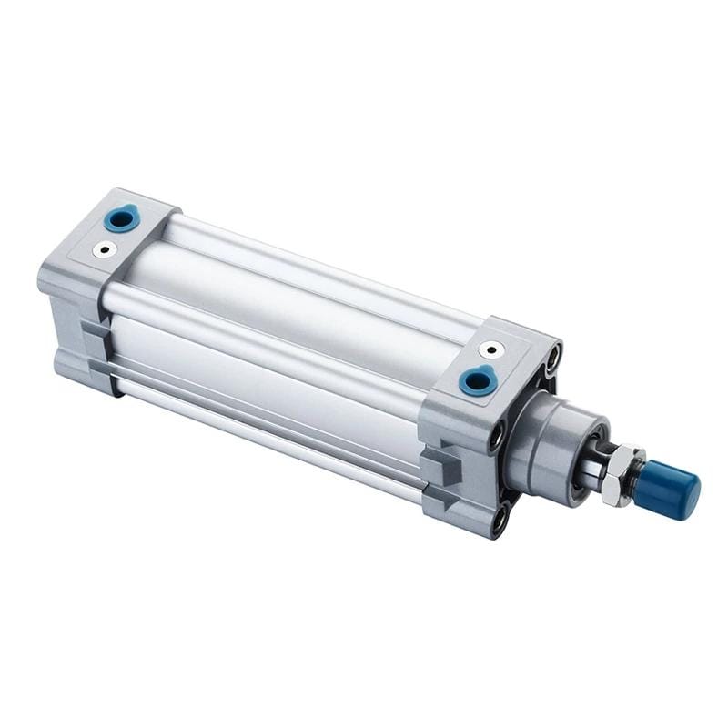
Parker states that 1 to 3 in3/min can be normal for piston-ring construction, while virtually no static leakage should be expected from a lip-seal piston (Parker Hydraulic and Pneumatic Cylinders, accessed 2026). Internal leakage therefore means chamber-to-chamber bypass, but its acceptance limit belongs to the exact cylinder design.
The piston seal’s job is to preserve the pressure difference that creates force. When air crosses that seal, it reaches the opposite chamber. It may then leave through a valve exhaust, raise pressure on the low-pressure side, or equalize between two blocked chambers.
Piston-seal bypass is chamber-to-chamber airflow across the moving piston sealing interface. That definition excludes rod-gland leakage to atmosphere, loose fittings, end-cap leakage, and flow that escapes inside the directional valve.
Don’t group every pneumatic loss under one label:
| Leakage path | Where the air moves | Typical evidence | First boundary check |
|---|---|---|---|
| Piston-seal bypass | Pressurized chamber to opposite chamber | Drift, weak hold, flow at opposite port | Test the cylinder separately from the valve |
| Rod-seal leakage | Working chamber to atmosphere at the gland | Hiss or measurable external flow | Inspect rod, gland, wiper, and rod seal |
| Valve internal leakage | Supply or work port to exhaust inside valve | Drift changes when valve is separated | Test valve and cylinder as separate components |
| Fitting or tube leak | Supply line to atmosphere | Ultrasound, bubbles where permitted, falling supply flow | Inspect the external circuit under its real pressure |
| Exhaust restriction | Chamber cannot vent freely | Slow or jerky motion, back pressure | Measure both cylinder ports during motion |
Drift is a symptom, not a component diagnosis. Parker specifically warns that apparent piston leakage isn’t always traceable to the piston. A valve spool, restricted exhaust, falling supply pressure, mechanical side load, or an elevated load can produce similar movement. For the repair-focused diagnostic sequence, use the separate guide to pneumatic cylinder internal-leakage causes and fixes. The broader cylinder sealing-system guide covers rod seals, wipers, wear rings, static seals, and running surfaces.
The Circuit State Determines Whether Leakage Becomes Continuous Cost
The U.S. Department of Energy reports that poorly maintained plants can lose 20 to 30 percent of compressor output through system leaks, not cylinder piston seals alone (DOE Sourcebook, 2003). Cylinder bypass becomes a continuing energy cost only when supply air replaces flow reaching an exhaust or another low-pressure sink.
Imagine a double-acting cylinder holding at the end of stroke. One work port remains connected to supply and the other to exhaust. If air crosses the piston seal, the compressor keeps replacing it. The leak is continuous for as long as that valve state remains active.
Change the valve state and the cost mechanism changes:
| Hold state | What piston bypass does | Energy-cost implication |
|---|---|---|
| One chamber supplied, opposite chamber exhausted | Crosses piston and leaves through exhaust | Continuous demand while the state is held |
| Both work ports blocked | Pressures move toward equilibrium | Finite equalization first; ongoing cost depends on other leak paths |
| Both work ports exhausted | No chamber stays supplied | Little continuous compressor demand from piston bypass alone |
| Closed-loop position control | Controller repeatedly adds air to correct drift | Intermittent or continuous demand plus control instability |
| Cylinder cycling normally | Bypass occurs during moving and dwell states | Cost depends on cycle time, dwell, pressure, and direction |
This is why a cylinder can create a serious holding problem without consuming the same amount of air in every circuit. It’s also why a compressor-room trend cannot assign cost to one actuator. Measure the branch or component under the valve state that produces the symptom.
If the machine spends 40 seconds of every minute holding a supplied chamber against an exhausted chamber, use that 67 percent hold duty in the cost estimate. Don’t charge the leak for 8,760 hours unless the leaking path is actually pressurized all year.
How Should You Measure Cylinder Internal Leakage?
SMC lists 10 cm3/min (ANR) internal leakage and 5 cm3/min external leakage for one C95SB160 actuator, proving that limits can be model-specific and condition-specific (SMC CP80-TFR12, 2013). A reliable test isolates the leak boundary, measures under stated conditions, and compares the result with the correct manual.
Compressed air can move a load after electrical power is removed. OSHA identifies pneumatic energy as hazardous stored energy and requires residual energy to be relieved, disconnected, restrained, or otherwise rendered safe before servicing (OSHA 29 CFR 1910.147 guidance). Only trained personnel should perform a pressurized test using the machine’s energy-control procedure and an approved fixture.
Use this measurement sequence:
- Record the cylinder model, bore, stroke, seal construction, working pressure, temperature, valve type, load direction, cycle state, and symptom.
- Check external leakage at fittings, tubes, end caps, the rod gland, and valve exhaust before blaming the piston.
- Measure both cylinder-port pressures during the faulty motion or hold. Static regulator pressure isn’t enough.
- Separate the cylinder test boundary from the control valve using the manufacturer’s approved procedure.
- Pressurize the specified chamber and measure flow at the opposite port, or use a validated pressure-decay setup with known volume.
- Repeat in the other direction. Bore damage, seal loading, rod position, and side load can make the two results different.
- Compare the rate with the exact model specification or a documented new-condition baseline.
Flow Measurement Versus Pressure Decay
A flow meter measures leakage directly when the flow range and reference condition fit the test. Record whether the result is stated as ANR, NL/min, SLPM, SCFM, or actual flow. A number without its reference condition isn’t ready for a cost calculation. Pressure decay estimates leakage from the known isolated volume, pressure change, elapsed time, and temperature assumption. It works best after temperature stabilizes and all production demand is removed from the test boundary. Use the Pressure Decay Leak Rate Calculator as a screening aid, then follow the cylinder manufacturer’s acceptance method.
One limitation matters: pressure decay shows that air left the isolated volume. By itself, it doesn’t prove whether the path crossed the piston, escaped at the rod gland, leaked through a fitting, or returned through the test valve. Boundary isolation supplies that diagnosis. In our application reviews, the fastest way to overstate leakage cost is to annualize a momentary test flow as though it were continuous. Record the valve state, hold duty, and number of pressurized hours before assigning an annual figure.
How Do You Calculate the Annual Cost of Internal Leakage?
CAGI defines compressor specific power as power required per delivered flow and publishes the annual energy relationship using motor power, operating hours, electricity rate, and efficiency (CAGI Resource Library, accessed 2026). For a measured cylinder leak, scale the package’s verified specific power by the leak flow and actual pressurized time.
Compressor specific power is the electrical input required to deliver a stated airflow at stated rating conditions. Use this screening formula only when the measured leak flow and compressor datasheet flow use the same reference basis, and the package specific power is given in kW per 100 cfm:
Annual leak energy (kWh) = leak flow (cfm on matched basis) / 100
                         x package specific power (kW/100 cfm)
                         x pressurized hours per year

Annual leak cost = annual leak energy x electricity rate
Use package input power, not motor nameplate power alone. The screening formula assumes compressor input changes in proportion to delivered flow, which isn’t true in every control mode. A fixed-speed load/unload machine can draw substantial power while unloaded, and a small repair may change unloaded time before it changes the electricity meter proportionally. Variable-speed and sequenced multi-compressor systems respond differently. Even so, the measured leak flow still quantifies wasted capacity and helps predict when the trim compressor can unload or shut down. Validate large projects with package power, flow, pressure, and control-state trends before and after repair. Demand charges, dryer losses, maintenance, and production effects also sit outside this simple energy estimate, so keep them as separate lines in the business case.
Worked Screening Example
Assume a cylinder bypass is measured at 2 cfm on the same reference basis as the compressor rating during its leaking hold state. The package uses 18 kW per 100 cfm, the state is pressurized for 6,000 hours per year, and electricity costs $0.12/kWh.
Annual energy = 2 / 100 x 18 x 6,000 = 2,160 kWh
Annual cost   = 2,160 x $0.12 = $259.20
The table below changes only the measured leakage rate. These are transparent calculations, not claimed plant results.
| Measured leak during supplied hold | Annual energy at stated assumptions | Screening cost per year |
|---|---|---|
| 0.5 cfm | 540 kWh | $64.80 |
| 2.0 cfm | 2,160 kWh | $259.20 |
| 5.0 cfm | 5,400 kWh | $648.00 |
What if the leak occurs only 25 percent of the operating time? Multiply the result by 0.25. What if 20 identical cylinders show the same verified 2 cfm loss during the same hold state? The screening total becomes $5,184 per year under these assumptions, before adding downtime or quality losses.
If the compressor datasheet reports different units, convert them before calculation. The Flow Converter can normalize SCFM, L/min, and m3/h, but keep the original reference conditions in the maintenance record.
Repair Priority: Cost, Production Risk, and Rebuild Condition
CAGI gives a 6.49 scfm external-orifice example costing $982 per year at 100 psig, 8,760 hours, and $0.10/kWh, which shows how strongly assumptions control a leak estimate (CAGI, accessed 2026). Internal bypass isn’t a known round hole, so rank it using measured flow plus process evidence rather than orifice size.
Energy cost is only one column. A small leak on a noncritical transfer cylinder may wait for planned maintenance. A lower-flow leak on a vertical clamp, safety-related fixture, precision stop, or bottling reject station may need immediate engineering review because motion or holding risk dominates the electricity value.
Use a repair queue like this:
| Evidence | Lower-priority pattern | Higher-priority pattern |
|---|---|---|
| Measured air cost | Low annual cost and short pressurized dwell | High continuous cost or many identical leaking units |
| Motion effect | Full stroke and stable timing | Drift, weak force, unstable speed, or failed position |
| Process consequence | Easy planned stop, no rejected product | Safety exposure, quality loss, bottleneck, or unplanned downtime |
| Cylinder condition | Clean bore and rod, guides intact | Scored bore, corroded rod, one-sided guide wear, repeated seal failure |
| Repair evidence | Correct kit and documented procedure available | Model unknown, obsolete parts, or several damaged hard components |
There is no defensible universal rule that says “rebuild whenever repair is below 60 percent of replacement cost.” Compare an actual seal-kit quote, labor, test time, expected service life, downtime, and the condition of the bore, rod, guides, and mounting. Rebuild when the running surfaces and structure are sound and the failure is confined to serviceable seals or guides. Replace or remanufacture when scoring, corrosion, bent parts, worn mounting interfaces, or repeat failures make a seal-only repair unlikely to hold.
Before accepting a substitute cylinder or seal kit, verify the model code, bore, stroke, rod diameter, ports, mounting, pressure, speed, environment, and seal material. The pneumatic cylinder range provides the product-family context, while the technical contact page is the right place to send drawings, photos, and measured leak data. Confirm the supplier route on the company information page before approving an undocumented replacement.
How Can You Prevent the Same Internal Leak From Returning?
ISO 8573-1 classifies compressed-air purity by three principal contaminant groups: particles, water, and oil (ISO 8573-1:2010, 2010). Preventing repeat piston bypass means matching those air conditions, plus alignment, pressure, temperature, lubricant, and seal material, to the cylinder manufacturer’s requirements rather than applying one filter grade everywhere.
Start with the failed parts. One-sided seal polish or guide wear points toward side load or misalignment. A longitudinal score in the bore can cut the replacement seal again. Swelling suggests chemical or lubricant incompatibility. Hardening can indicate heat or aging. Embedded debris shifts attention toward air treatment, dirty tubing, or assembly cleanliness.
Then close the loop:
- Record baseline leakage in both directions.
- Measure pressure at the cylinder ports during real motion, not only at the regulator.
- Inspect every running and guiding surface: rod, bore, piston seal, wear rings, wiper, guides, and mounting alignment.
- Match the replacement seal and lubricant to verified temperature, cycle rate, chemical exposure, and the exact groove geometry rather than visual similarity alone.
- Specify particles, water, and oil with the required ISO 8573-1 class.
- Retest under the recorded baseline conditions.
Use the ISO compressed-air quality guide when contamination is suspected. If dynamic port pressure collapses while the cylinder moves, investigate the pressure-drop path before fitting another seal kit. Force still depends on pressure differential and effective piston area, as explained in the pneumatic force guide.
FAQs About Pneumatic Cylinder Internal Leakage Cost
Parker’s 1 to 3 in3/min piston-ring example and SMC’s 10 cm3/min (ANR) model limit differ in both construction and units (Parker; SMC). These answers therefore use measured conditions and model specifications rather than one percentage for every pneumatic cylinder.
How much internal leakage is acceptable in a pneumatic cylinder?
There is no universal percentage. Parker permits 1 to 3 in3/min for piston-ring construction but expects virtually no static leakage from piston lip seals. SMC lists 10 cm3/min (ANR) for one C95SB160 actuator. Use the exact model manual, stated pressure, direction, temperature, and test method.
Can pressure drop per minute determine whether a cylinder has failed?
Pressure decay can estimate leakage only when test volume, start pressure, end pressure, time, and temperature behavior are known. A 5 percent drop has different meaning in a small cylinder and a large isolated volume. Compare the calculated flow with the model limit, and isolate piston bypass from fittings, valves, and rod-seal leakage.
How much can one leaking pneumatic cylinder cost per year?
It depends on measured flow and duty. At 2 cfm on the matched rating basis, 18 kW per 100 cfm, 6,000 pressurized hours, and $0.12/kWh, the proportional screening cost is $259.20 per year. Actual utility savings depend on compressor controls, while downtime, reject, and safety consequences may outweigh the energy figure.
Does a drifting cylinder always waste compressed air continuously?
No. With one chamber supplied and the other exhausted, piston bypass can create continuous demand. With both ports blocked, the first effect may be pressure equalization and drift rather than continuous exhaust flow. Measure the actual valve state and hold duty, such as 40 seconds per minute, before annualizing cost.
Should you repair the seals or replace the entire cylinder?
Repair when the bore, rod, guides, mounting, and hard parts remain serviceable and a correct seal kit is available. Replace or remanufacture when scoring, corrosion, bent parts, or repeat failures remain. Don’t use a universal three-year age or 60 percent cost rule; compare actual quotations, downtime, and verified condition.
The reliable cost number starts with a reliable leak boundary. Identify where the air crosses, measure it in the real circuit state, use verified compressor data, and repeat the same test after repair. That turns an invisible maintenance complaint into a documented energy and reliability decision.
External technical references and retrieval dates
- Parker Hannifin, Hydraulic and Pneumatic Cylinders: Construction-specific internal-leakage guidance and warning that drift may originate elsewhere in the circuit. Retrieved 2026-07-14.
- SMC, CP80-TFR12 Installation and Maintenance Manual: Model-specific internal and external leakage values, safe maintenance instructions, inspection, and seal replacement. Retrieved 2026-07-14.
- U.S. Department of Energy, Improving Compressed Air System Performance: Plant-level leak-loss range, system pressure-decay method, and compressed-air economics. Retrieved 2026-07-14.
- CAGI, Working With Compressed Air: Compressed-air cost formula, specific examples, pressure effects, and system-efficiency guidance. Retrieved 2026-07-14.
- CAGI Resource Library: Specific-power definition and compressed-air calculation resources. Retrieved 2026-07-14.
- ISO 8573-1:2010: Compressed-air purity classes for particles, water, and oil. Retrieved 2026-07-14.
- OSHA, Control of Hazardous Energy guidance: Control of pneumatic stored and residual energy before service. Retrieved 2026-07-14.
- SMC video, MB Series Air Cylinder Maintenance Procedure: Model-specific cylinder disassembly, seal handling, greasing, and reassembly demonstration. Retrieved 2026-07-14.