

Pneumatic cylinder bore size affects air consumption through piston area, which increases with the square of bore diameter. At equal stroke and pressure, moving from a 50 mm bore to 63 mm increases cap-end swept volume by 58.8%. That extra volume is charged every powered stroke, so cycle rate and annual operating hours turn a small sizing step into a recurring cost.
The lowest-air cylinder isn’t automatically the right one. Bore must still provide enough force at the lowest dynamic pressure, in both directions, with allowances for friction, acceleration, exhaust back pressure, mounting geometry, and load variation. The practical goal is the smallest standard bore that passes the complete motion and risk review.
Key Takeaways
- Piston area and cap-end air demand follow bore diameter squared.
- A complete double-acting cycle also includes rod-side volume and switched tubing.
- Convert added L/min into kW with the compressor’s verified specific power.
- Downsize only after dynamic force, stroke time, cushioning, and machine safety pass.
Why Does Bore Diameter Change Air Use So Quickly?
Bore changes air use quickly because piston area equals pi x bore^2 / 4. AutomationDirect’s sizing table lists a 2 inch bore at 3.14 in2 and a 4 inch bore at 12.57 in2, almost exactly four times the area (AutomationDirect Cylinder Sizing, accessed 2026).
Cylinder bore is the internal barrel diameter that sets the piston’s full cap-end pressure area. It isn’t the cylinder body’s outside width.
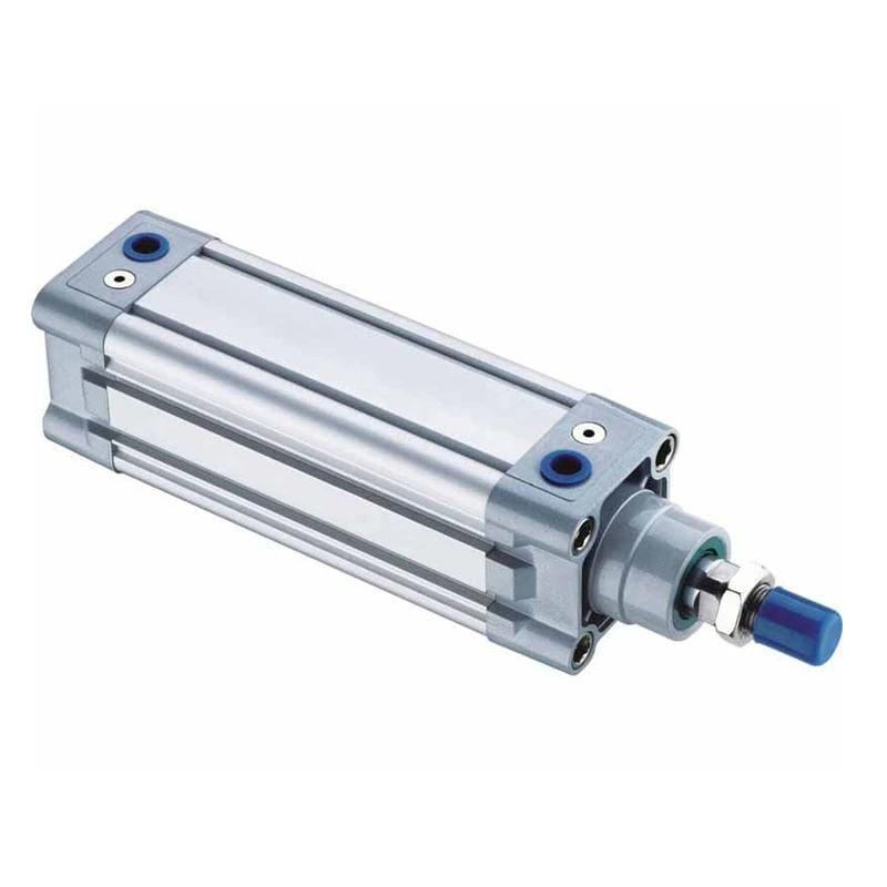
That square relationship is easy to underestimate when moving between catalog sizes. A 26% diameter increase from 50 mm to 63 mm produces a 58.8% increase in piston area. Moving from 63 mm to 80 mm adds about 27% diameter but 61.2% area. The percentage change in air demand is therefore much larger than the number printed in the bore column suggests.
Use the cap-end swept-volume equation to isolate bore:
Piston area = pi x bore^2 / 4
Cap-end swept volume = piston area x stroke
Approximate free-air equivalent = swept volume x absolute pressure ratio
At 6 bar gauge, a first-pass pressure ratio is about 7 because the chamber is near 7 bar absolute while the reference atmosphere is near 1 bar absolute. NIST defines one standard atmosphere as 101,325 Pa and warns that standard gas-flow units can use different reference temperatures (NIST Pressure and Gas Flow Conversions, updated 2025). State the reference basis whenever values from different catalogs are compared.
The following table holds stroke at 500 mm and pressure at 6 bar gauge. It shows cap-end air only, so the bore effect stays visible without rod-size differences.
| Bore | Piston area | Cap-end swept volume | Approx. free-air equivalent | Index vs. 40 mm |
|---|---|---|---|---|
| 40 mm | 1,257 mm2 | 0.628 L | 4.40 L | 1.00 |
| 50 mm | 1,963 mm2 | 0.982 L | 6.87 L | 1.56 |
| 63 mm | 3,117 mm2 | 1.559 L | 10.91 L | 2.48 |
| 80 mm | 5,027 mm2 | 2.513 L | 17.59 L | 4.00 |
Does doubling bore double air use? No. It quadruples cap-end volume when stroke and final pressure remain unchanged. The broader bore-size force and speed guide explains the same area relationship from the force and flow side; this article carries it into annual operating cost.
How Should Cylinder Air Consumption Be Calculated?
A complete calculation includes both cylinder chambers, cycles per minute, and valve-to-cylinder tubing. SMC’s 50 mm bore, 600 mm stroke, 0.5 MPa example uses about 13 L per cylinder cycle plus 0.56 L for two meters of 6 mm-ID piping (SMC Model Selection Guide, accessed 2026).
Free-air equivalent is the expanded volume reported at a stated atmospheric reference condition, not the smaller physical volume inside a pressurized cylinder chamber.
For a single-rod double-acting cylinder, extension and retraction volumes differ:
Extension swept volume = piston area x stroke
Retraction swept volume = (piston area - rod area) x stroke
Cylinder free-air per cycle =
  (extension swept volume + retraction swept volume) x pressure ratio

Total free-air per minute =
  (cylinder air per cycle + switched tubing air per cycle) x cycles per minute
Festo provides a useful check. Its DNC-50-500 example at 4.5 bar uses about 4.5 L on extension and 3.8 L on retraction, or 8.3 L for the double stroke (Festo Operating Conditions and Standards, accessed 2026). The rod-side deduction is not optional.
The next table uses a 500 mm stroke, 6 bar gauge, and representative rod diameters. These rod sizes are calculation inputs, not a universal ISO assignment. Replace them with the selected catalog values.
| Bore / rod | Extension air | Retraction air | Cylinder air per cycle | At 20 cycles/min |
|---|---|---|---|---|
| 40 / 16 mm | 4.40 L | 3.69 L | 8.09 L | 162 L/min |
| 50 / 20 mm | 6.87 L | 5.77 L | 12.64 L | 253 L/min |
| 63 / 20 mm | 10.91 L | 9.81 L | 20.72 L | 414 L/min |
| 80 / 25 mm | 17.59 L | 15.87 L | 33.47 L | 669 L/min |
These are approximate cylinder-only free-air equivalents. They exclude tube volume, valve cavities, pilot air, leakage, blow-off, vacuum generators, incomplete chamber filling, and overlapping machine movements. SMC distinguishes air consumption used for compressor and cost estimates from required flow used for speed and component sizing. Don’t use one number for both jobs.
For a measurement-first boundary that includes switched piping and actual machine flow, use the double-acting cylinder air-consumption guide. The cylinder formula reference covers the area and force equations behind the inputs.
What Changes When You Move to the Next Standard Bore?
ISO 15552:2018 covers detachable-mounting cylinders from 32 mm through 320 mm at a maximum rated pressure of 1,000 kPa, or 10 bar. ISO confirmed the edition in 2025, but its scope is dimensional interchangeability, not application energy performance (ISO 15552, confirmed 2025).
Moving to the next standard bore changes more than the purchase specification. It raises cap-end force and volume together, changes rod-side volume according to the selected rod, increases the flow required for the same stroke time, and may change the valve port, tube ID, cushion setting, mounting envelope, and moving mass.
The table below separates the recurring air penalty from other selection consequences:
| Bore step | Diameter increase | Cap-end area increase | Example full-cycle increase | Main engineering rechecks |
|---|---|---|---|---|
| 40 to 50 mm | 25.0% | 56.3% | 8.09 to 12.64 L, 56.2% | Force reserve, valve flow, tube ID |
| 50 to 63 mm | 26.0% | 58.8% | 12.64 to 20.72 L, 63.9% | Dynamic pressure, cycle time, cushioning |
| 63 to 80 mm | 27.0% | 61.2% | 20.72 to 33.47 L, 61.5% | Porting, exhaust flow, impact energy |
Why is the full-cycle increase slightly different from the cap-end area increase? The rod diameter changes the annular area. A catalog with a larger rod may improve buckling capacity but reduce retract-side chamber volume and retract force area. Use the exact bore and rod pairing from the selected model.
The most useful purchasing question isn’t “How much bigger is 63 than 50?” It is “What recurring air volume am I accepting to gain the required force margin?” That phrasing forces the RFQ to show dynamic pressure, load, cycle rate, and annual hours alongside the bore.
If the application is a direct replacement, dimensional compatibility must also be checked. The ISO 15552 interchangeability guide covers mounting centers, rod thread, ports, accessories, and sensor provisions that an air-use calculation cannot verify.
Turning Air Demand Into Annual Cost
CAGI defines compressor specific power as the electrical input required to deliver 100 cfm at a stated discharge pressure. Its verified data sheets report package power and flow so buyers can compare compressors on a common basis (CAGI Performance Verification, accessed 2026). Use site data, not a universal cost per cubic meter.
Compressor specific power is package input power divided by delivered free-air flow at stated test conditions. Lower values indicate less input power for the same reported flow.
The operating-cost sequence is:
Average free-air flow (m3/min) = air per cycle x cycles per minute / 1000
Actuator-equivalent power (kW) = average flow x package specific power
Annual energy (kWh) = actuator-equivalent power x active hours per year
Annual cost = annual energy x electricity price
Specific power may be published as kW/100 cfm. NIST gives 1 cfm = 28.31685 L/min, so 100 cfm = 2.831685 m3/min (NIST Pressure and Gas Flow Conversions, updated 2025). Keep the compressor pressure and flow basis aligned with the air-consumption estimate.
Here is an illustrative comparison using the full-cycle values above:
- 20 complete cycles per minute
- 4,000 active production hours per year
- Package specific power of 7 kW per m3/min
- Electricity price of $0.12/kWh
- No tubing, leakage, pilot-air, or part-load correction
| Bore / rod | Flow at 20 cycles/min | Actuator-equivalent power | Annual energy | Illustrative annual cost |
|---|---|---|---|---|
| 40 / 16 mm | 0.162 m3/min | 1.13 kW | 4,532 kWh | $544 |
| 50 / 20 mm | 0.253 m3/min | 1.77 kW | 7,081 kWh | $850 |
| 63 / 20 mm | 0.414 m3/min | 2.90 kW | 11,604 kWh | $1,392 |
| 80 / 25 mm | 0.669 m3/min | 4.69 kW | 18,742 kWh | $2,249 |
The scenario shows why site-specific inputs matter. Moving from 50 to 63 mm adds roughly 4,523 kWh and $543 per active year under these assumptions. It isn’t a universal savings claim. A modulating compressor, unloaded power, storage, pressure band, simultaneous demand, and production downtime can all change the real electrical result.
For an installed machine, compare cost per accepted production cycle rather than compressor power during a short test. Rejects, idle pressurization, leaks, and longer cycle time can erase a theoretical bore saving. The Compressed Air Energy Cost Calculator can screen annual kWh and cost after measured average flow and package specific power are available.
When Is a Larger Bore Worth the Extra Cost?
AutomationDirect recommends calculated cylinder force at least 25% above the actual requirement as a starting allowance for friction, pressure drop, and related effects. Its 4 inch bore example produces 1,257 lbf at 100 psi before practical deductions (AutomationDirect Cylinder Sizing, accessed 2026).
A larger bore is justified when the smaller option cannot pass a documented force check at the lowest expected differential pressure. It may also be justified when load variation, acceleration, vertical motion, exhaust back pressure, seal friction, wear, or machine risk demands more margin than a simple static calculation provides.
Use this order:
- Calculate required force from the real load and motion direction.
- Use pressure measured at both cylinder ports during the demanding part of motion.
- Apply one documented sizing factor or manufacturer load ratio.
- Calculate extension and retraction separately.
- Select the next available bore that passes the force check.
- Verify valve flow, tube ID, exhaust capacity, stroke time, and cushioning.
The correct formula is:
Required theoretical force = actual load x selected application factor
Required effective area = required theoretical force / dynamic pressure differential
Required bore = sqrt(4 x required area / pi)
Do not divide required area by a safety factor greater than one. That would make the selected bore smaller as the requested margin increases. The Cylinder Bore Size Calculator applies load, pressure, direction, rod diameter, friction allowance, and safety factor before suggesting a common metric bore.
What if a large bore is being used to hide low dynamic pressure? Measure first. A restricted filter, undersized valve, long small-ID tube, clogged silencer, or excessive exhaust back pressure can make a correctly sized cylinder look weak. The working-pressure guide and pressure-drop troubleshooting guide show where to place gauges and what to record under flow.
How Can You Audit an Oversized Cylinder Safely?
Festo documents a DSBC 32-500 example that used about 5.1 Nl per cycle at 6 bar, then about 4.0 Nl when return pressure was reduced to 3 bar, a 22% reduction without changing bore or stroke (Festo Energy Efficiency, accessed 2026).
That example shows why “replace the cylinder” shouldn’t be the first audit action. The excess demand may come from bore, pressure, tubing dead volume, unnecessary powered return force, leakage, or idle pressurization. Isolate those variables before ordering hardware.
Use a controlled audit sequence:
- Define the boundary. Name the cylinder, valve, switched tubing, manifold branch, and production state included.
- Record geometry. Capture bore, rod diameter, stroke, action type, port size, and tube ID and length.
- Measure the load. Include gravity, acceleration, process force, friction, and the worst credible product condition.
- Measure dynamic pressure. Record both cylinder ports during acceleration and peak process force.
- Establish the baseline. Log accepted cycles, cycle time, idle flow, and normal or standard air over a representative run.
- Model one change. Compare the next smaller bore or a lower return pressure without mixing several modifications.
- Check risk controls. Review lost-air behavior, stored energy, guarding, lockout, and restart conditions.
- Run a controlled trial. Confirm load, timing, cushioning, temperature, rejects, and repeatability.
- Verify the result. Compare air per accepted cycle under the same production conditions.
Downsizing can reduce air demand while creating a new failure mode. A smaller bore may stall during low supply pressure, extend cycle time, increase sensitivity to seal friction, or require higher pressure that cancels part of the saving. Long-stroke compression loads also need a separate rod-buckling check. Bore alone doesn’t solve the load path.
The audit should produce a traceable decision: retain the bore, downsize, split extension and return pressures, shorten switched tubing, repair leakage, or correct a flow restriction. If none of those options passes the process and safety checks, the current air cost may be the justified cost of reliable motion.
A Bore-Size Decision Worksheet
The U.S. Department of Energy lists more than 40 MEASUR calculators, including Pneumatic Air Requirement and compressor operating-cost calculations for industrial systems (DOE MEASUR Calculator List, accessed 2026). A useful project worksheet connects geometry, production demand, compressor performance, and acceptance evidence in one record.
| Input group | Record these values | Why it matters |
|---|---|---|
| Motion | Load, direction, acceleration, stroke, target time | Establishes required force and flow |
| Cylinder | Bore, rod, stroke, action type, mounting | Establishes chamber volume and load path |
| Pressure | Supply, cap-port, rod-port, exhaust back pressure | Establishes real differential force |
| Circuit | Valve model, tube ID and length, fittings, silencer | Adds switched volume and pressure loss |
| Production | Cycles/min, active hours, rejects, idle state | Converts cycle air into annual demand |
| Compressor | Flow basis, pressure, package specific power, control mode | Converts air demand into electrical demand |
| Cost | Electricity price, maintenance assumptions, project cost | Supports payback without a generic claim |
| Acceptance | Force, stroke time, cushion, temperature, quality, safety | Prevents an energy change from harming the machine |
The decision rule is simple: choose the smallest standard bore that passes every required operating state, then calculate its recurring air demand with the actual rod, stroke, pressure, and cycle rate. If two bores both pass, compare annual cost and implementation risk. If only the larger bore passes, document why.
Keep the worksheet with the machine. Future maintenance teams can compare dynamic port pressure, cycle air, and stroke time with a known-good baseline instead of increasing pressure or bore from guesswork. That record also improves replacement RFQs because suppliers receive the operating boundary, not just a cylinder part number.
FAQs: What Should Engineers Check Before Changing Bore?
NIST lists 1 atmosphere as exactly 101,325 Pa and 1 cfm as 28.31685 L/min, while warning that “standard” flow may use different reference temperatures (NIST Pressure and Gas Flow Conversions, updated 2025). These unit details directly affect every bore comparison and annual cost estimate.
Does doubling pneumatic cylinder bore quadruple air consumption?
Doubling bore quadruples piston area and cap-end swept volume when stroke and final pressure are unchanged. A complete double-acting cycle won’t be exactly four times unless rod diameter scales consistently because the return chamber uses annular area. SMC also counts valve-to-cylinder piping in the operating air boundary (SMC, accessed 2026).
Does a smaller bore always reduce operating cost?
A smaller bore reduces chamber volume, but it may need higher pressure, longer stroke time, or a different circuit to move the load. AutomationDirect recommends at least 25% calculated force above actual demand as a starting point. If the smaller bore fails dynamic force or timing checks, its lower theoretical air use isn’t an acceptable saving (AutomationDirect, accessed 2026).
Should I lower pressure or reduce bore first?
Test the force requirement in each direction before changing either variable. Festo’s 32 mm by 500 mm example cut cycle air from about 5.1 Nl to 4.0 Nl by reducing only return pressure from 6 to 3 bar. That 22% result applies to its stated circuit, not every machine (Festo, accessed 2026).
How do I estimate annual cylinder air cost?
Calculate free-air flow from air per cycle and cycles per minute, multiply flow by verified compressor package specific power, then multiply resulting kW by active hours and electricity price. CAGI defines specific power on a stated flow and discharge-pressure basis, so use the compressor data sheet or measured system value (CAGI, accessed 2026).
Why is measured air use higher than the cylinder formula?
The basic formula covers cylinder chambers. SMC’s worked example adds 0.56 L of switched piping to 13 L of cylinder air before multiplying by ten cylinders and five cycles per minute. Leakage, pilot air, valve cavities, blow-off, vacuum demand, and idle flow can widen the gap further (SMC, accessed 2026).
Sources and Calculation Basis
The source set uses primary standards, government tools, and manufacturer engineering data. SMC’s worked case totals 678 L/min for ten 50 mm bore cylinders cycling five times per minute after adding 13 L of cylinder air and 0.56 L of piping per cycle (SMC, accessed 2026).
- ISO 15552:2018, detachable-mounting cylinder scope, 32-320 mm bore range, 1,000 kPa maximum rated pressure, confirmed current in 2025. Retrieved 2026-07-14.
- SMC Best Pneumatics: Air Cylinders Model Selection, cylinder and piping air consumption, cycles-per-minute calculation, compressor margin, and required-flow distinction. Retrieved 2026-07-14.
- Festo: Operating Conditions and Standards in Pneumatics, DNC-50-500 double-stroke air-consumption example and formula inputs. Retrieved 2026-07-14.
- Festo: Energy Efficiency, 32 mm by 500 mm two-pressure example and stated 22% reduction. Retrieved 2026-07-14.
- AutomationDirect: Cylinder Sizing and Force, pressure-area equations, rod-side force, bore table, and 25% starting force allowance. Retrieved 2026-07-14.
- CAGI: Performance Verification, package specific-power definition, verified compressor data-sheet basis, and power-cost method. Retrieved 2026-07-14.
- NIST: Pressure and Gas Flow Unit Conversions, atmosphere, psi, cfm, L/min, and standard-flow reference cautions. Updated 2025; retrieved 2026-07-14.
- U.S. Department of Energy: MEASUR Calculator List, pneumatic air requirement and compressor operation-cost calculation scope. Retrieved 2026-07-14.