

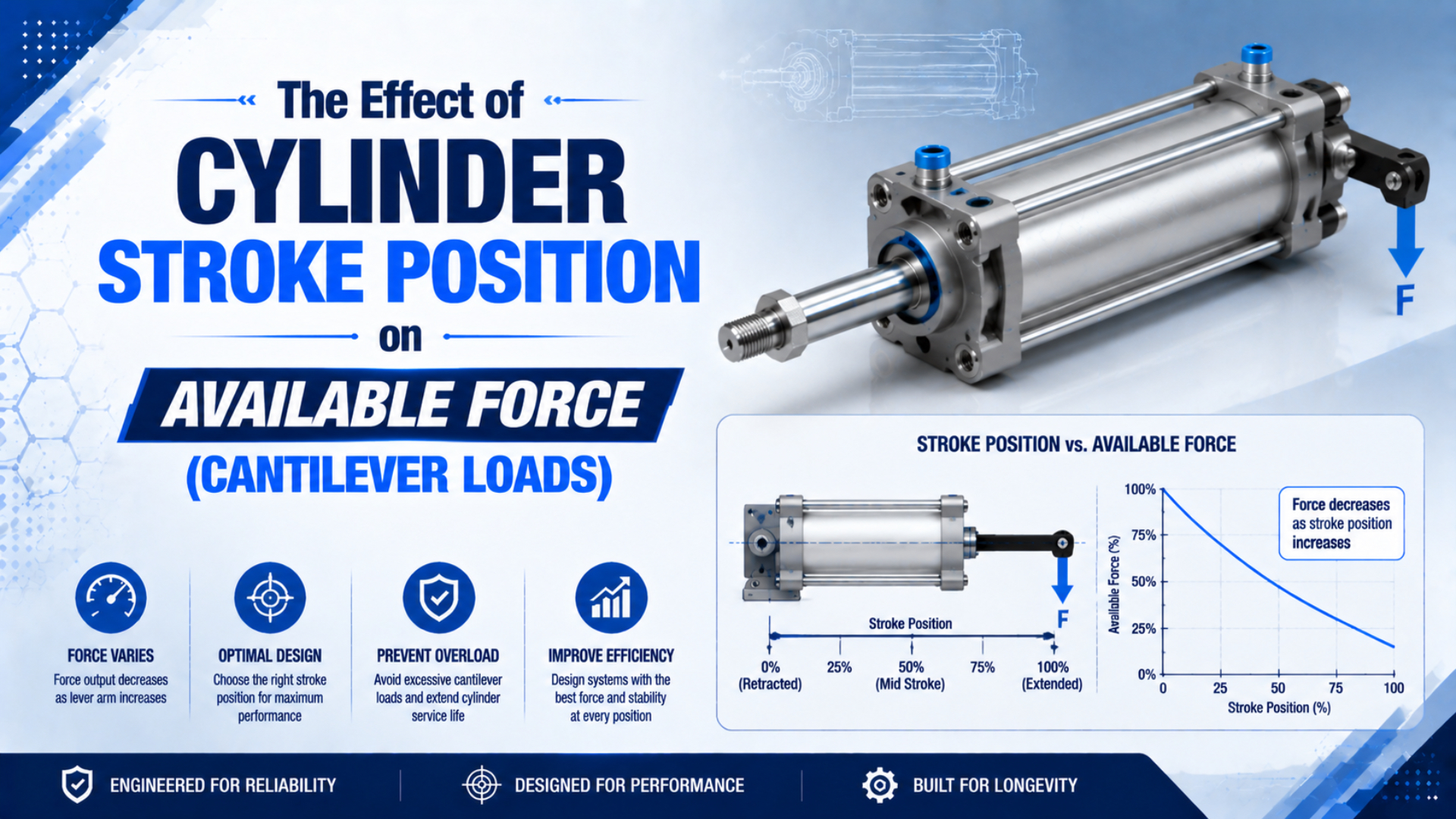
Cylinder stroke position does not directly reduce pressure-generated axial force. If effective pressure and piston area remain the same, theoretical thrust is the same when the rod is retracted, at mid-stroke, or fully extended. What changes with extension is the mechanical condition: a longer lever arm increases bending moment and deflection, while a longer unsupported rod has less resistance to buckling.
This distinction matters because an actuator can have enough pneumatic thrust and still be unsafe for the applied side load. A sound design therefore separates three questions: Can the cylinder generate the required axial force? Can its rod, bearing, and mounting tolerate the transverse load and moment at this position? Is the extended rod stable under compression?
Key Takeaways
- Parker defines theoretical cylinder force from pressure and effective piston area, not piston position.
- Festo publishes transverse-load checks using both stroke length and lever arm; one DSBC example permits only 9.5 N under its stated geometry.
- Parker requires alignment checks with the rod both extended and retracted.
- Full extension is often the worst structural case, but it is not automatically the worst pressure-force case.
Does Stroke Position Change Pneumatic Cylinder Force?
No, not by itself. For a conventional double-acting cylinder, axial force comes from the pressure acting on the effective areas of the piston, minus opposing pressure and friction. Stroke position is absent from that force balance. Parker expresses the basic theoretical relationship as force equals pressure multiplied by area in its pneumatic actuator catalog.
For an extending cylinder, a more complete force balance is:
where:
- is the usable axial force in newtons (N).
- and are the effective cap-end and rod-end pressures in pascals (Pa).
- is the full piston area in square metres (m²).
- is the rod-side annular area in square metres (m²).
- includes seal and bearing friction in newtons (N).
Real force can vary during a stroke because chamber pressure, exhaust back pressure, seal friction, acceleration, or supply flow changes. Those are pressure and dynamics effects. They should not be described as an automatic cantilever-force derating caused by position.
For the pressure-area calculation and unit conversions, see our complete pneumatic cylinder theoretical force guide.
The useful design distinction is between generated axial force and allowable mechanical load. The first can remain nearly constant while the second falls as the rod extends. Treating them as one number hides the actual failure mechanism.
Why Can Full Extension Still Reduce the Safe Load?
Extension increases the distance between the side load and the cylinder’s supporting bearing or mounting. The same transverse force therefore creates a larger bending moment. Festo’s DSBC engineering data explicitly evaluates transverse force as a function of stroke length and lever arm rather than subtracting it from axial thrust.
The basic moment relationship is:
Here, is bending moment in newton-metres (N·m), is transverse force in newtons, and is the perpendicular lever arm in metres. If stays at 100 N while grows from 0.05 m to 0.35 m, the moment rises from 5 N·m to 35 N·m even though the pressure-generated thrust is unchanged.
That moment can increase rod-bearing contact pressure, seal wear, mounting deflection, and misalignment. Parker’s Cylinder Safety Guide warns that cylinder rods are normally not designed for bending moments or loads perpendicular to their motion.
Which Three Cylinder Limits Must Stay Separate?
A cylinder selection is incomplete until pneumatic thrust, transverse loading, and rod stability have each passed their own check. Theoretical cylinder force is the pressure-generated axial output. Transverse load is force applied perpendicular to the motion axis. Bending moment is the turning effect of that force at an offset. These limits cannot be collapsed into one universal derating percentage.
| Design check | Governing variables | What position changes | Required evidence |
|---|---|---|---|
| Axial force | Effective pressure, piston and annular areas, friction | Nothing directly; pressure and friction may change during motion | Pressure calculation or measured chamber pressures |
| Transverse load and moment | Side force, lever arm, bearing and mounting geometry | Lever arm and manufacturer-permitted side load | Exact model’s lateral-load or moment chart |
| Rod deflection | Side force, unsupported length, modulus, second moment of area | Deflection rises rapidly with unsupported length | Beam screening plus catalog limits |
| Compression buckling | Rod diameter, effective length, end condition, material | Longer effective length lowers the critical load | Manufacturer buckling or maximum-stroke chart |
For a simplified cantilever with a tip load, elastic beam theory gives:
The cubic length term explains why a modest increase in unsupported length can produce a much larger deflection. This equation assumes an ideal, slender, linearly elastic beam with a fixed support. NASA’s beam-deflection reference supports the relationship, but an actual cylinder also has bearing clearance, mounting compliance, seals, and non-ideal load introduction. Use our cylinder deflection guide for the detailed screening method.
For an ideal compression member, Euler’s critical load is:
The term represents the end-condition factor. This equation is useful for screening, not for overriding a manufacturer’s rating. SMC’s rod buckling selection data shows that maximum usable stroke depends on bore, operating pressure, and mounting arrangement. You can use the pneumatic cylinder rod buckling calculator to organize an initial check, then confirm it against the selected model’s catalog.
What Does a Three-Position Worked Check Show?
Consider a 63 mm bore cylinder operating at 6 bar with a constant 100 N transverse load. Festo’s current ISO-cylinder data lists 1,870 N theoretical advance force for this bore and pressure. That value does not change across the three positions below; the illustrative bending moment changes sevenfold because the assumed lever arm grows from 50 mm to 350 mm.
| Position | Theoretical advance force at 6 bar | Assumed lever arm | Transverse load | Resulting moment |
|---|---|---|---|---|
| Retracted | 1,870 N | 50 mm | 100 N | 5 N·m |
| Mid-stroke | 1,870 N | 200 mm | 100 N | 20 N·m |
| Full extension | 1,870 N | 350 mm | 100 N | 35 N·m |
The moment values come from and are an illustration, not a rating for a particular 63 mm cylinder. The 1,870 N force comes from Festo’s ISO cylinder technical catalog, which lists theoretical force by bore, direction, and pressure separately from stroke.
This example reveals why “available force” needs a qualifier. Pneumatically, 1,870 N remains available under the stated ideal conditions. Mechanically, the cylinder may be unable to use all of it safely if 35 N·m exceeds the rod bearing, mounting, or external guide limit. The next step is to compare each position with the selected model’s transverse-force and moment charts.
Festo’s DSBC example illustrates the scale of those limits: for its stated 32 mm cylinder, 150 mm stroke, and 84 mm lever arm, the permissible transverse force is 9.5 N. That number belongs only to the documented geometry and model. It should not be generalized to other bores or mounting arrangements.
How Should You Check a Real Machine?
Check the actual load path at retracted, intermediate, and fully extended positions, then repeat the review for static, accelerating, and stopped conditions. Parker specifically calls for alignment to be checked with the rod both extended and retracted. Adding an intermediate position catches linkages whose force direction changes during the stroke.
- Draw the load path. Mark the cylinder axis, payload centre of gravity, attachment points, external guides, and every offset from the rod centreline.
- Calculate effective axial force. Include pressure on both sides of the piston, exhaust back pressure, friction allowance, and the required safety margin.
- Resolve transverse forces. Include gravity, belt or linkage reactions, hose forces, acceleration, stops, and impact loads. Do not count only the payload weight.
- Calculate moment at each position. Use the actual lever arm from the relevant cylinder bearing, mount, or guide datum specified by the manufacturer.
- Check model-specific ratings. Compare side force, bending moment, stroke, speed, and mounting orientation with the exact catalog, not a generic bore-size table.
- Check compression stability. Use the manufacturer’s rod buckling or maximum-stroke chart for the selected mount and pressure.
- Verify alignment through the whole stroke. Parker notes that improper alignment can accelerate gland and bore wear. A dial indicator or alignment fixture can expose a bind that a retracted-only inspection misses.
In our experience, the fastest design review uses three columns for retracted, mid-stroke, and full extension. Recording axial pressure force, transverse moment, and buckling status separately makes an unsafe assumption visible before it becomes a seal-wear or rod-bearing problem.
For mounting trade-offs, see which cylinder mounting type maximizes load capacity. For correction methods when the load cannot be kept axial, use our guide to mitigating side-load issues.
When Do You Need an External Guide or Different Actuator?
Add external guidance when the machine load creates meaningful side force or moment that the cylinder is not explicitly rated to carry. SMC instructs designers to use an external guide when allowable lateral load could be exceeded because excess side load affects the bearing and piston seal. Its guidance appears in the C96 cylinder operation manual.
Common solutions include:
- A linear rail or guide shaft that carries payload weight and moments while the cylinder supplies only axial drive force.
- A guided cylinder with published pitch, yaw, roll, and transverse-load ratings.
- A trunnion, clevis, or spherical connection that allows the actuator to follow an intentional arc without binding.
- Two synchronized guides around a central cylinder when the load has a wide or offset centre of gravity.
- A rodless guided actuator when space is limited, provided its carriage moment ratings cover the real load.
A rodless cylinder does not automatically eliminate cantilever loading. An unguided or poorly supported carriage can still see pitch, yaw, and roll moments. Compare the actuator’s published moment capacity with the payload geometry, just as you would check a piston rod. Our rodless versus standard cylinder comparison explains the architectural differences.
A Position-by-Position Design Review
Approve the application only when every independent limit passes at every relevant position and operating state. A high calculated thrust does not compensate for a failed side-load or buckling check. Conversely, a well-guided load does not fix inadequate pressure force.
Use this decision sequence:
- First, verify that effective axial force exceeds the required process force with an appropriate engineering margin.
- Second, verify that transverse force and each applied moment remain below the exact actuator or guide ratings.
- Third, verify rod buckling for compression, especially near full extension and for pivoted mounts.
- Fourth, verify deflection and alignment against the machine’s positional and seal-life requirements.
- Finally, confirm speed, cushioning, stop loads, and pressure transients under the real duty cycle.
Do not add force, moment, deflection, and buckling values into one “capacity” number; their units and failure modes differ. The safe design is the one in which none of these checks becomes the limiting failure condition.
Cylinder Stroke Position and Cantilever Load FAQs
The questions below separate pressure-generated thrust from position-dependent structural limits. ISO 15552 covers interchangeable mounting dimensions for cylinders with 32 mm to 320 mm bores and rated pressure up to 1,000 kPa, but it does not provide one universal side-load allowance. Use the exact manufacturer and model data for those limits. See the ISO 15552 scope.
Does cylinder force decrease as the rod extends?
Not automatically. If effective chamber pressure, piston area, and friction remain the same, theoretical axial force is independent of rod position. Measured force can change because pressure drops, exhaust back pressure, seal friction, acceleration, or valve flow changes during motion. Diagnose those effects separately from cantilever loading.
Why can an extended rod fail if thrust is unchanged?
Extension increases the lever arm for a transverse load and the unsupported length of a rod in compression. The resulting bending moment, deflection, bearing load, or buckling risk can exceed a mechanical limit even when the cylinder continues to generate the same theoretical pressure force.
Can I use beam equations as cylinder ratings?
No. Beam and Euler equations are useful screening tools under stated ideal assumptions. A real cylinder includes bearing clearance, mounting compliance, threads, shoulders, seals, and manufacturer-specific safety criteria. Use calculations to identify risk, then accept or reject the design using the exact model’s published load and buckling data.
Does a rodless cylinder eliminate cantilever loading?
No. A rodless design removes an external piston rod, but its carriage and guide can still experience transverse force plus pitch, yaw, and roll moments. A guided rodless actuator may handle these loads well, but only within its published force and moment ratings at the actual payload offset.
Which stroke positions should be checked?
Check at least retracted, mid-stroke, and full extension, plus any position where linkage geometry, payload orientation, acceleration, or an external stop changes. Parker specifically requires alignment checks in extended and retracted states. Compression buckling and transverse moment are often most demanding near full extension, but linkage reactions can peak elsewhere.