

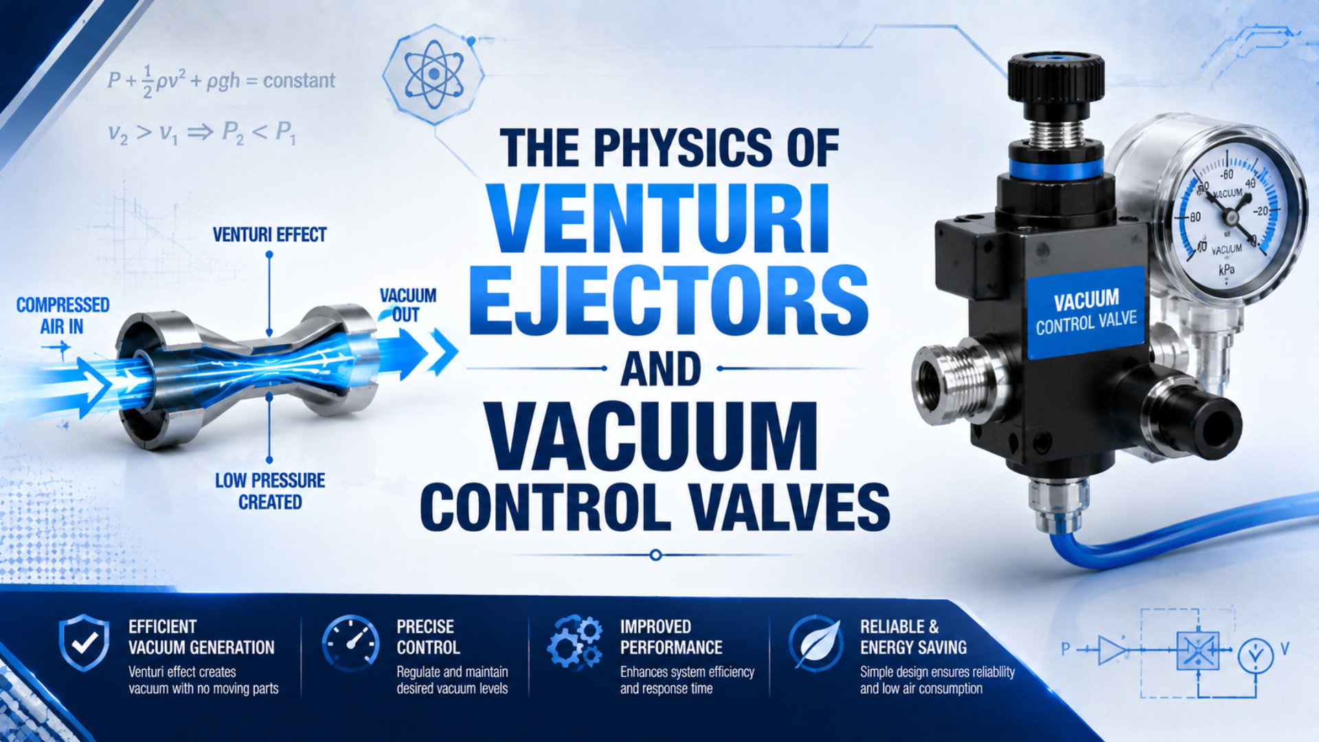
A Venturi ejector is a pneumatic vacuum generator that expands compressed motive air through a nozzle, entrains air from a suction port, mixes the streams, and recovers pressure in a diffuser. Its performance is governed by compressible flow and the complete flow path, not by Bernoulli’s equation alone.
Don’t select an ejector from maximum vacuum alone. Read its supply-pressure curve, air consumption, suction flow versus vacuum, and evacuation-time data at the same operating point. Design the controls around leakage, required holding pressure, response time, and safe release.
Key Takeaways
- Commercial ejectors commonly list maximum vacuum around 80-90 kPa below atmosphere, but that is a sealed-port condition, not usable suction flow.
- Nozzle flow can choke at Mach 1, so Bernoulli alone cannot predict ejector capacity.
- Vacuum switches, hysteresis, and check valves can stop motive air after the holding threshold is reached.
How Does a Venturi Ejector Generate Vacuum?
A pneumatic ejector has three external ports and at least four internal flow zones. SMC identifies compressed-air supply, vacuum, and exhaust as the basic connections, while its ZQ series lists standard supply pressures from 0.35 to 0.43 MPa depending on nozzle size (SMC ZQ Series).
The sequence is easier to understand if the motive and suction streams are kept separate:
- Motive air enters the supply port. Upstream pressure and temperature establish the available gas density and energy.
- The nozzle accelerates the motive air. Static pressure falls as the gas expands toward the nozzle outlet.
- Low pressure at the suction chamber draws in secondary air. This is the air removed from the cup, tube, manifold, or vessel.
- The two streams exchange momentum in the mixing section. Entrainment is not free; it changes both velocity and pressure.
- The diffuser slows the mixed stream and recovers part of its static pressure. The combined flow then exhausts to atmosphere.
Why Is Bernoulli’s Equation Not Enough?
Choked flow is the condition in which a nozzle throat reaches Mach 1 and cannot pass more mass flow merely by lowering downstream pressure. NASA’s compressible-flow derivation shows this maximum at the smallest flow area, which is why an air ejector cannot be modeled as constant-density flow (NASA Mass Flow Choking).
Bernoulli’s equation remains a useful qualitative entry point: velocity rises while static pressure falls along an ideal streamline. It does not, by itself, predict the motive mass flow, suction mass flow, mixing loss, shock behavior, diffuser recovery, or exhaust back pressure in a real ejector.
From our analysis of manufacturer curves, the useful mental model is not “small passage equals vacuum.” The nozzle establishes a high-speed motive jet, while the complete geometry determines how much secondary flow that jet can entrain at the required suction pressure. A narrow nozzle can limit motive mass flow even at high velocity.
Three boundaries matter:
| Boundary | What controls it | What the buyer should request |
|---|---|---|
| Motive-flow limit | nozzle throat, upstream absolute pressure, temperature | air consumption versus supply pressure |
| Suction performance | entrainment chamber, mixing geometry, leakage | suction flow versus vacuum pressure |
| Exhaust recovery | diffuser, silencer, downstream back pressure | allowed exhaust restriction and noise data |
The entrainment ratio is sometimes written as:
Here, is the secondary suction mass flow and is the primary motive mass flow. The ratio depends on the stated pressure and temperature conditions. A catalog ratio without those conditions isn’t transferable to another ejector or operating point.
For more detail on the sonic boundary, see the guide to sonic conductance and critical pressure ratio.
Reading an Ejector Performance Curve
Maximum vacuum is the sealed-port endpoint, not the flow available during evacuation. For example, SMC’s 0.5, 0.7, and 1.0 mm ZQ nozzles list maximum suction flows of 5, 10, and 22 L/min, while motive-air consumption is 15, 25, and 47 L/min (SMC ZQ Series).
A real application operates between two catalog endpoints. Maximum vacuum is measured with the suction port sealed and flow near zero. Maximum suction flow is measured near atmospheric pressure at the suction port, where usable vacuum is near zero.
SMC’s explanation of vacuum flow curves makes the relationship explicit: sealing the suction port produces maximum vacuum at zero suction flow, while opening it increases suction flow and lowers vacuum pressure (SMC ZM Series). Porous workpieces and leaks move the operating point toward higher flow and lower vacuum.
| Catalog value | Test condition it represents | Common misuse |
|---|---|---|
| Maximum vacuum | sealed or nearly sealed suction port | treated as guaranteed vacuum under leakage |
| Maximum suction flow | low vacuum, open inlet condition | used as flow available at the holding setpoint |
| Air consumption | stated supply pressure and reference condition | compared without checking ANR, NL/min, or SCFM basis |
| Evacuation time | stated volume, tube, pressure target, and test circuit | scaled only by cup size while ignoring tubing and fittings |
Some ejectors reach their intended point below plant header pressure. Excess supply pressure can add motive-air use and noise without a proportional suction gain. Regulate locally and follow the selected model’s curve.
Use absolute pressure in gas calculations:
For vacuum, is negative. A reading of -85 kPa gauge corresponds to roughly 16 kPa absolute at standard atmosphere. See the absolute-pressure guide for conversion details.
Vacuum Control Valves: Regulation and Air Saving
An energy-saving ejector does not need to consume motive air for the entire holding period. Festo’s VADM/VADMI documentation describes a vacuum switch, supply solenoid valve, non-return valve, and air-saving function that restarts generation only when vacuum falls below the set range (Festo VADM/VADMI).
The term “vacuum control valve” can refer to several different components. Define the function before selecting a part:
| Component | Primary job | Typical control variable |
|---|---|---|
| Ejector supply valve | starts and stops motive air | PLC command or local logic |
| Vacuum switching valve | connects or isolates a pump source | cycle state |
| Non-return valve | holds vacuum after generation stops | pressure differential |
| Vacuum switch or sensor | reports holding threshold and loss | vacuum pressure |
| Vacuum regulator | limits or stabilizes a vacuum level | downstream vacuum setpoint |
| Blow-off valve | admits positive air for fast release | timed release command |
For a sealed workpiece, the efficient sequence is usually:
- Open the motive-air valve.
- Confirm that the vacuum crosses the safe-pick threshold within the allowed time.
- Stop motive air at the upper threshold.
- Hold vacuum through the non-return valve.
- Restart the ejector if leakage pulls vacuum below the lower threshold.
- At placement, isolate vacuum and apply a short, controlled blow-off pulse.
Vacuum-switch hysteresis is the pressure band between air shutoff and restart. Too narrow a band makes the valve chatter; too wide a band may reduce holding margin. Monitor time between restarts. Shortening intervals are a useful leakage and cup-wear signal.
Evacuation-Time Estimate
For a closed volume with constant effective pumping speed, Leybold gives the simplified logarithmic relationship between volume, pumping speed, initial pressure, and target pressure. Leybold also warns that conductance, leakage, desorption, and changing pumping speed make real pump-down slower (Leybold Pump-Down Time).
The simplified estimate is:
where:
- is evacuation time;
- is the total evacuated volume, including cup, tube, fittings, and manifold;
- is effective suction flow at the connected volume;
- is initial absolute pressure;
- is target absolute pressure.
For example, take a 2.0 L volume, 1013 mbar initial absolute pressure, 400 mbar target pressure, and 20 L/min effective suction flow. The idealized result is about 5.6 seconds.
That result is a screening estimate. Ejector flow normally falls as vacuum rises, so constant is an approximation. Use the manufacturer evacuation curve when response time is a release criterion. SMC likewise selects ejectors and switching valves from suction capacity and adsorption response time (SMC Vacuum Equipment Selection).
Long tubing can dominate a small cup’s volume and restrict conductance. For rapid pick confirmation, mount the ejector close to the suction point and route compressed air to it instead of running a long vacuum line to a cabinet.
How Should You Size a Vacuum Ejector for a Real Load?
Vacuum level alone does not size a handling system. Schmalz defines theoretical cup holding force as pressure difference multiplied by effective suction area, , and notes that surface condition and application dynamics require a separate safety factor (Schmalz Vacuum Suction Cups).
Use two independent checks:
- Holding-force check: Can the cups support gravity, acceleration, orientation, and process forces at the minimum allowed vacuum?
- Flow and response check: Can the ejector remove the initial volume and continuous leakage quickly enough to reach that vacuum?
The ideal static relationship is:
Here, is theoretical normal holding force, is ambient pressure minus cup pressure, and is the manufacturer’s effective suction area. Apply acceleration, orientation, friction, uneven load sharing, surface texture, contamination, cup wear, and a suitable safety factor separately.
Higher vacuum isn’t automatically better. SMC notes that doubling vacuum pressure doubles theoretical lifting force, while doubling cup diameter quadruples it. Excessive vacuum can also lengthen response time, consume more energy, and shorten pad life (SMC Vacuum Equipment Model Selection).
A larger cup at moderate vacuum can outperform a small cup near maximum vacuum. Check force with the Vacuum Suction Cup Force Calculator, then select ejector flow from leakage and response time.
For operating cost, use measured air consumption and actual on-time in the Vacuum Generator Air Cost Calculator. Air-saving logic changes duty cycle, not the instantaneous motive-air flow.
What Causes Low Vacuum, Slow Response, or High Air Use?
Start with the symptom because maximum vacuum and maximum suction flow occur at opposite ends of the performance curve. SMC’s flow-curve guidance says leakage raises suction flow while reducing vacuum, so a system can show high flow and low vacuum without the ejector itself being defective (SMC ZM Series).
| Symptom | Most likely checks | Diagnostic clue |
|---|---|---|
| Low final vacuum | cup seal, porous part, cracked tube, blocked nozzle, exhaust back pressure | vacuum improves when suction port is capped |
| Slow evacuation but acceptable final vacuum | excessive volume, long narrow tube, clogged filter, undersized ejector | capped test reaches target, but connected system is slow |
| High motive-air use | supply pressure too high, no air-saving logic, leakage-driven restarts | air continues after the safe-pick threshold |
| Unstable vacuum signal | narrow hysteresis, sensor mounted far away, pulsating leak | rapid valve cycling around one pressure point |
| Slow or unreliable release | missing blow-off, restricted vent, sticky or deformed cup | vacuum remains after the supply valve closes |
| Excessive noise | high supply pressure, damaged or clogged silencer, restricted exhaust | back pressure changes vacuum performance |
Run three tests before replacing the ejector:
- Cap the suction port. This tests achievable vacuum with virtually no secondary flow.
- Measure evacuation time on a known volume. This tests usable suction capacity.
- Record supply pressure at the ejector while flowing. This catches upstream pressure drop that a static regulator gauge misses.
These tests separate sealing, flow, and supply faults. Correct capped vacuum with slow evacuation points to conductance or capacity. Low capped vacuum points to the nozzle, silencer, supply, or ejector. If both checks pass, investigate the machine-side leak or workpiece.
Inspect the compressed-air path too. An undersized valve, fitting, or tube can reduce dynamic supply pressure even when the ejector inlet reads correctly at rest. The guides to pneumatic pressure drop and pneumatic tubing routing cover those upstream checks.
See About Bepto for author context. For a circuit review, contact engineering with the model, pressure, target vacuum, evacuation time, volume, and leakage.
Venturi Ejector FAQs: What Should Engineers Verify?
Manufacturer examples span different operating points rather than one universal specification. SMC lists ZQ maximum vacuum around -80 kPa, while Schmalz lists some high-vacuum ejectors at -850 to -900 mbar; both still require model-specific suction-flow and air-consumption checks (SMC ZQ; Schmalz SBPL).
What vacuum level can a Venturi ejector achieve?
Many industrial models specify maximum vacuum in the range of roughly 80-90 kPa below atmospheric pressure, but the value is model-specific and normally measured near zero suction flow. Check the curve at the application’s leakage flow. State the result as gauge vacuum or absolute pressure so the requirement cannot be misread.
Does higher supply pressure always create more vacuum?
No. Each ejector has a recommended or standard supply pressure. Above that point, motive-air consumption and noise may rise without a proportional performance gain. Use dynamic inlet pressure and the selected model’s curve. A plant header at 0.6 MPa does not mean every ejector should receive 0.6 MPa.
What is the difference between maximum suction flow and maximum vacuum?
Maximum suction flow occurs near low vacuum with the suction port open. Maximum vacuum occurs near zero suction flow with the port sealed. A real cup or vessel operates between those points. Select from the curve at the required vacuum, not by combining the two catalog maxima as if they occurred together.
When should an air-saving vacuum circuit be disabled?
Continuous suction may be more stable for porous workpieces or large continuous leaks. Festo warns that rapid leakage can cause frequent switching and provides logic that can revert to continuous suction when cycling becomes excessive. For sealed parts, a check valve and pressure-switch hysteresis can sharply reduce motive-air on-time.
How should a vacuum ejector be selected for a porous workpiece?
Measure or conservatively estimate the continuous leakage at the required holding vacuum. Then choose an ejector whose suction-flow curve can sustain that operating point with margin. A high maximum-vacuum rating alone is unsuitable. Test the actual material, cup geometry, filter, tube, and cycle before approving the machine release.
Sources and technical references
- NASA Glenn Research Center: Mass Flow Choking, compressible nozzle mass flow and the Mach 1 choking condition. Retrieved 2026-07-19.
- SMC ZQ Series Vacuum Ejector, nozzle size, standard supply pressure, maximum suction flow, air consumption, and maximum vacuum. Retrieved 2026-07-19.
- SMC ZM Series Vacuum Ejector, explanation of vacuum-pressure and suction-flow curves. Retrieved 2026-07-19.
- SMC Vacuum Equipment Model Selection, ejector and switching-valve selection from suction capacity and response time. Retrieved 2026-07-19.
- Festo VADM/VADMI Vacuum Generator, integrated supply valve, vacuum switch, check valve, blow-off pulse, and air-saving control. Retrieved 2026-07-19.
- Schmalz Vacuum Suction Cups, pressure-difference and effective-area holding-force relationship. Retrieved 2026-07-19.
- Leybold: How to Calculate Pump-Down Time, constant-effective-speed evacuation estimate and its limits. Retrieved 2026-07-19.