


Route pneumatic tubing by separating fixed runs from moving runs, selecting the exact tube for the pressure, temperature, environment, and motion, then keeping every bend above the applicable manufacturer limit. Give moving tube a controlled path and neutral length. Protect it from abrasion, heat, chips, pinch points, and connector loads. Finally, cycle the complete machine while watching the tube path and measuring pressure at peak demand. Pneumatic tubing routing is both a mechanical-motion problem and a compressed-air flow problem. A visually tidy route can still twist a fitting, flatten in a carrier, or starve an actuator.
Key Takeaways
- Use the tube manufacturer’s stated bend radius; one 6 mm Festo tube specifies 12 mm minimum and 26.5 mm flow-relevant radii.
- Let moving tube travel freely without tension, twisting, tangling, or uncontrolled rubbing.
- Validate the final route through every machine state and peak-flow event.
What Must You Define Before Routing Pneumatic Tubing?
ISO 4414:2010 applies pneumatic-system safety principles across design, assembly, installation, operation, and maintenance (ISO 4414, confirmed 2021). Start the route by documenting every machine state, not by drawing the shortest line between two ports. The route must remain acceptable during production, setup, cleaning, faults, and service.
Create a routing input sheet before choosing clips or a carrier. Record the tube material, outside and inside diameter, working pressure, temperature range, fluid, chemical exposure, cleanliness requirement, flame behavior, and whether the product is approved for static or dynamic service. The lowest rating among tube, fitting, valve, and environment controls the circuit.
What can move into this path?
Then map the machine itself:
- Mark fixed ports, moving ports, full axis travel, rotation, acceleration, and dwell positions.
- Add guards, doors, tooling changes, product paths, cable bundles, coolant spray, hot surfaces, sharp edges, and chip fall zones.
- Identify the approved energy-isolation points, exhaust paths, gravity loads, and actuators or accumulators that can retain hazardous energy after the air supply has been isolated.
- Define the required actuator pressure and timing during the highest simultaneous-flow event.
- Preserve access.
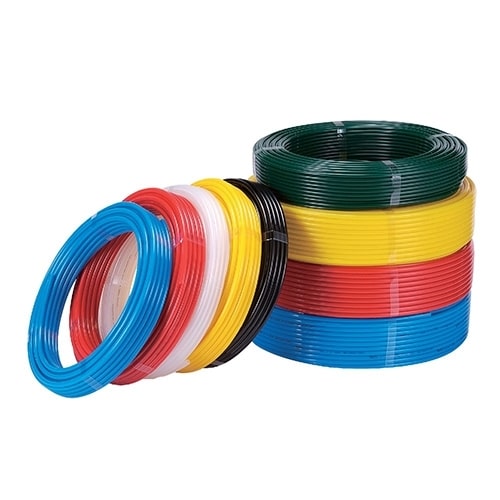
Color can help identify circuits, but it isn’t proof of material, pressure rating, or bend performance. Keep the part number and route identifier in the machine documentation. When corrosion, washdown, or chemical exposure affects the connection, review the complete tube-and-fitting interface alongside the pneumatic fitting material guide.
Treat each route as two overlapping systems. The mechanical route controls bending, tension, rubbing, and access. The pneumatic route controls line volume, flow resistance, pressure drop, and response. Passing one review doesn’t prove the other has passed.
How Should You Choose Bend Radius for Fixed and Moving Tubes?
A 6 mm Festo PUN-V0 tube lists a 12 mm minimum bending radius but a 26.5 mm flow-relevant radius (Festo datasheet, 2026). That difference is why a universal rule such as eight times outside diameter cannot replace the exact datasheet or the carrier manufacturer’s dynamic requirement.
The minimum bend radius usually describes a stated test condition. It may be a static limit rather than a repeated-flex limit. It also may not describe the radius needed to preserve the tube’s effective bore. If a bend approaches the minimum, check whether the datasheet separately lists a flow-relevant radius, dynamic radius, or energy-chain approval.
Which radius actually governs the bend?
Classify the route before choosing a number:
| Route condition | Radius decision | Evidence required |
|---|---|---|
| Fixed tube with no movement | Stay at or above the product’s stated static radius | Exact tube datasheet and installed temperature |
| Tube moves occasionally for service | Add neutral length without loading the fitting | Full service motion and connector-load check |
| Repeated linear travel | Use tube approved for the carrier and its dynamic radius | Tube and carrier documentation plus cycle test |
| Multi-axis or torsional motion | Use a product and guide intended for 3D motion | Defined torsion, travel, speed, and test life |
| Continuous rotation | Replace twisting tube with a suitable rotary interface | Media, pressure, speed, port count, and seal compatibility |
For moving use, SMC warns that the published minimum radius for its TUZ tubing assumes static piping; extra tube length and the radius specified by the flexible protection system are required (SMC TUZ precautions, retrieved 2026-07-14). Don’t create that length as a random loose loop. Establish a neutral position, move the axis through its full envelope, and confirm that the tube never becomes taut, buckles, or pushes sideways on the fitting.
How Do You Route Tubing Through Linear Cable Carriers?
igus recommends 5-10% all-around clearance for pneumatic hoses in an energy chain and calls for interior separation above 0.5 m/s and 10,000 cycles per year in the stated high-speed case (igus carrier guidance, retrieved 2026-07-14). Use the carrier’s rules as a system, not as isolated percentages.
Choose the carrier bending radius from the stiffest or largest-radius service inside it. Then verify that the installed tube can move freely through the curved section. It must not be pulled against the inner radius, crushed against the outer radius, stacked where it can tangle, or forced around a divider edge.
Where does the tube change direction?
For a linear axis:
- Start untwisted.
- Keep different diameters and jacket materials separated when they could cross, stick, or abrade.
- Distribute service weight across the carrier width rather than loading one side.
- Follow the carrier and tube instructions for strain relief at the moving and fixed ends, including any required distance between the strain-relief point and the active bending segment.
- Keep the transition from the carrier to the machine smooth and outside the active bending segment.
- Verify the upper and lower runs at maximum travel, acceleration, and deceleration.
Extra length is correct only when it lets the tube follow the designed path. Too little transfers tension to the fitting. Too much can create a migrating loop that rubs, crosses another service, or becomes trapped at the end of travel. Judge length by the full motion envelope, not by a fixed percentage added to the axis stroke.
If valves can be moved closer to the actuator without compromising safety or service access, compare centralized and distributed architectures using the pneumatic valve placement guide. A shorter moving bundle may be better than placing more tube inside a larger carrier.
What Changes in Multi-Axis and Continuous-Rotation Motion?
SMC’s first TUZ piping caution prohibits ordinary tube connections where the connection itself slides or rotates and directs users to rotary-type fittings for such motion (SMC TUZ precautions, retrieved 2026-07-14). Separate repeated bending, torsion, limited rotation, and continuous rotation because each creates a different load.
Conventional linear carriers control one plane. A robot wrist or articulated mechanism may combine bending, twisting, axial pull, and changing contact points. Model every axis combination, including homing, manual jogging, recovery moves, tool changes, and maintenance positions. The worst tube state may not occur during the normal production cycle.
Can the route untwist itself? It can’t.
Create a motion-state matrix before selecting the dress pack. Put each axis position on one side and every possible companion state on the other, then record where the tube enters a carrier, changes plane, approaches a guard, or transfers load into a fitting. Include the nonproduction states that technicians actually use: homing, manual jog, fault recovery, tool release, maintenance access, and power-off settling. The matrix exposes conflicts that a single animation can hide. Review it with the electrical and mechanical layouts because a safe pneumatic path can still collide with a cable connector, coolant hose, sensor bracket, or removable panel. Mark the neutral tube position, permitted contact zones, forbidden contact zones, and inspection viewpoints on the released drawing. That record gives commissioning and maintenance teams something objective to compare against after the machine has run.
Choose the motion-control method from the actual envelope:
| Motion | Preferred routing concept | Reject when |
|---|---|---|
| Single-axis reciprocation | Linear carrier or guided loop | Tube rubs, stacks, or loads a port |
| Limited angular motion | Controlled arc with defined neutral position | Tube twists at the connector |
| Multi-axis robotic motion | 3D carrier or dress pack rated for the motion | Bend and torsion cannot be separated or verified |
| Continuous rotation | Rotary union or rotary pneumatic interface | Tube accumulates twist with each revolution |
Rotary unions transfer a pressurized fluid from a stationary inlet to a rotating outlet (DSTI rotary-union overview, retrieved 2026-07-14). Selection still requires pressure, media, rotational speed, port count, leakage allowance, seal material, temperature, and service-life data. A swivel fitting that relieves installation alignment is not automatically a continuous-duty rotary union.
How Should Fixed Tubing Be Supported and Protected?
SMC identifies 3 connector loads to avoid: twisting, pulling, and moment loading (SMC TUZ precautions, retrieved 2026-07-14). Fixed pneumatic tubing therefore needs enough support to control its path without clamping it so tightly that the support flattens the bore or transfers thermal and assembly stress into a fitting.
There is no universal support spacing for every tube size, material, orientation, temperature, vibration level, and machine geometry. Follow the machine builder’s standard and the tube/support manufacturer’s instructions. Add support where gravity, vibration, a direction change, or a nearby connector would otherwise let the tube move or pull.
What happens when vibration moves the bundle?
Protect fixed runs from:
- unfinished holes;
- hot surfaces, radiant heat, and nearby equipment whose normal operating temperature can reduce the tube’s allowable pressure or accelerate material aging;
- weld spatter, chips, coolant, cleaning chemicals, and UV exposure;
- footsteps, carts, dropped tools, and closing guards;
- repeated rubbing against cables, hoses, frames, or moving products;
- vacuum collapse or pressure-related length change outside the product specification.
Rounded guides, compatible grommets, sleeves, conduit, guards, or stand-off supports belong where the risk assessment calls for them. A sleeve isn’t a cure for uncontrolled motion. If the tube keeps sawing across an edge, redesign the path or guide the motion before adding another sacrificial layer.
Keep connectors accessible and avoid bending the tube immediately at the collet. Cut the tube square with the specified tool, inspect the end, insert it fully, and perform the fitting manufacturer’s retention check. Labels should remain readable after the machine is assembled. The circuit should be traceable without pulling on the bundle.
How Do Tube Length and Bends Affect Pneumatic Response?
CAGI says well-designed compressed-air systems generally keep compressor-to-use pressure drop within 10% and recommends sufficient tube diameter with the minimum necessary length (CAGI pressure-drop brief, retrieved 2026-07-14). On a machine, tube inside diameter, length, fittings, bends, valve capacity, and peak flow determine the dynamic result.
Long routes add internal volume that must be filled and exhausted. A small inside diameter raises resistance. A tight or flattened bend can further reduce the effective flow area. These effects become visible during a fast cylinder stroke, simultaneous actuator demand, or an exhaust-limited return, even when the static pressure gauge looks normal.
Which pressure matters? The moving one.
Measure the route under the real event:
- Identify the event.
- Record supply pressure at the valve or manifold and pressure at the actuator port on the same time base so the two traces can be compared without guessing about timing.
- Capture command time, motion start, stroke completion, and the highest simultaneous demand.
- Compare the measured result with the valve, fitting, tube, and actuator requirements.
- Move the sensor one segment at a time when isolating an unexpected loss.
Screen tube length and inside diameter with the compressed-air pressure-drop calculator, then confirm the route with live measurements. The pneumatic tube volume calculator helps when line volume may delay filling, exhausting, or purge response. Neither tool detects a pinched tube, carrier interference, or a poor fitting insertion.
The shortest route isn’t automatically the fastest safe route. A slightly longer path with a larger effective radius and no flattened section can outperform a visually direct path that chokes near a port. Compare routes by measured dynamic pressure and timing, not centerline length alone. The broader pressure-drop troubleshooting guide helps separate local routing loss from upstream supply problems.
Installation and Commissioning Checklist
Four tube conditions appear in SMC’s periodic inspection guidance: physical damage, leakage, twisting or crushing, and material deterioration (SMC TUZ precautions, retrieved 2026-07-14). Commissioning should establish a clean baseline for those checks and prove the route through every approved operating state before production release.
Does it still clear at speed?
Before pressurization:
- Confirm every tube part number, fitting size, route label, and port destination against the drawing.
- Check square cuts, full insertion, retention, connector alignment, guards, dividers, clips, and strain relief.
- Verify the tube remains above the applicable bend radius and doesn’t carry twist from the coil.
- Move each axis manually through its permitted envelope where the validated procedure allows it, then repeat the critical combined-axis states that can place the bundle closest to guards or tooling.
- Photograph the baseline.
During controlled start-up, keep personnel clear of motion and stop on unexpected movement, noise, leakage, or tube displacement. Test single axes first, then the highest-risk combined motion. Repeat at production speed and load. Watch both ends of every carrier, transitions into fixed routing, robot wrist zones, and points hidden when guards are closed.
Record route photographs at defined machine positions, minimum observed clearance, applicable bend-radius values, pressure and timing traces, leak-test result, and any inspection points. If the system contains high-speed motion, compare the routing review with the high-speed pneumatic cylinder checklist.
Maintenance Inspection and Replacement
OSHA 29 CFR 1910.147 requires control of hazardous energy during covered servicing, including stored or residual energy (OSHA 1910.147, retrieved 2026-07-14). Inspect pneumatic tubing through the site’s approved isolation procedure, and never disconnect a line or fitting merely because the supply valve appears closed.
The commissioning record reveals change. Fresh polishing, dust, or colored transfer at a contact point can show rubbing before the tube leaks. A route that shifts sideways in the carrier may indicate a failed divider, strain relief, or transition. Oil, coolant, heat, UV, and cleaning chemistry can change tube hardness or surface condition.
Has the path moved since release?
Replace the tube when the manufacturer or risk assessment requires it, or when inspection finds cracking, gouging, flattening, crushing, hardening, softening, leakage, damaged labeling, loss of retention, or an unapproved repair. Don’t patch a damaged pneumatic tube for reuse. Investigate the route before installing the replacement, or the new tube will inherit the same failure mechanism.
After replacement, repeat the relevant commissioning steps instead of checking only for an audible leak. Confirm the part number, radius, neutral length, full motion envelope, fittings, carrier behavior, pressure, and cycle time. For actuator-specific service planning, connect the route inspection to the rodless-cylinder preventive maintenance checklist.
FAQ
Three manufacturer values summarize the routing method: one 6 mm Festo tube lists 12 mm minimum and 26.5 mm flow-relevant radii, while igus recommends 5-10% pneumatic-hose clearance in its carrier guidance (Festo and igus, retrieved 2026-07-14). Use product-specific limits rather than universal spacing rules.
What minimum bend radius should I use for pneumatic tubing?
The exact tube datasheet controls the answer. Distinguish static, flow-relevant, and dynamic values. One 6 mm Festo PUN-V0 tube specifies a 12 mm minimum radius and 26.5 mm flow-relevant radius. A different material or size can require another value, especially in an energy chain or repeated-flex application.
How much extra tube should I leave for a moving axis?
Don’t use a universal percentage. SMC says moving tubing needs extra length, but the correct amount must keep the tube neutral through the full motion without tension, buckling, rubbing, or connector load. Set the length from the actual axis envelope, carrier geometry, bend radius, and transition points, then verify it at speed.
Can pneumatic tubing share an energy chain with electrical cables?
It can when the carrier, tube, cables, and machine rules allow it. igus recommends 5-10% clearance around pneumatic hoses and uses separators where services could stack, tangle, or interfere. Check voltage segregation requirements separately, distribute weight, prevent incompatible jackets from sticking, and keep every service free to move through the carrier radius.
Should I support fixed pneumatic tubing every 12 to 18 inches?
Not as a universal rule. Required spacing changes with tube material, diameter, orientation, vibration, temperature, route geometry, and support design. SMC instead focuses on preventing twist, pull, moment load, crushing, and damage. Follow the machine and component instructions, then add support wherever the installed tube can move, sag, rub, or load a connector.
How do I verify that a tubing route isn’t restricting airflow?
Measure pressure at the valve supply and actuator port during the highest-flow event, then compare motion timing with the requirement. CAGI recommends sufficient tube diameter and minimum necessary length, with no more than 10% compressor-to-use loss in a well-designed system. Inspect tight bends and flattened sections before raising supply pressure.
Sources and Retrieval Notes
ISO, ISO 4414:2010 Pneumatic Fluid Power. System safety and lifecycle scope. Retrieved 2026-07-14.
Festo, PUN-V0-6X1-RT Datasheet. Minimum and flow-relevant bending radii. Retrieved 2026-07-14.
SMC, Series TUZ Tubing and Precautions. Moving-tube, fitting-load, and inspection guidance. Retrieved 2026-07-14.
igus, Energy Chain Cable and Hose Installation Guidance. Clearance, separation, bend-radius, and strain-relief guidance for moving services. Retrieved 2026-07-14.
CAGI, Technical Brief on Pressure Drop. Tube diameter, length, and pressure-drop guidance. Retrieved 2026-07-14.
OSHA, 29 CFR 1910.147. Hazardous-energy control during servicing. Retrieved 2026-07-14.
DSTI, What Is a Rotary Union?. Rotary fluid-interface definition. Retrieved 2026-07-14.
igus, How to Assemble E2.1 e-chain Cable Carrier. Carrier assembly video. Retrieved 2026-07-14.