


Eliminate push-in fitting leaks by treating the tube and fitting as one specified assembly. Match the tube outside diameter and material to the exact fitting series, make a clean square cut, push the tube to the internal stop, perform a light pull check, support the connected tube, and verify the joint under the approved test procedure.
That method is more reliable than adding sealant or replacing every fitting that hisses. ISO 14743 covers complete push-in connector assemblies used with thermoplastic tube from 3 mm through 16 mm outside diameter. Therefore, compatibility and performance belong to the assembly, not to the fitting body alone (ISO 14743:2021, 2021).
Push-in connector assembly is the fitting, its internal gripping and sealing elements, and the tube specified to work with them under defined pressure, temperature, media, and installation conditions.
Key Takeaways
- Match the exact tube outside diameter, material, hardness, pressure, temperature, and media to the fitting series.
- Cut square with a tube cutter, inspect the sealing surface, insert to the stop, and pull lightly to confirm retention.
- Diagnose tube-side, thread-side, and fitting-body leaks separately before deciding what to replace.
Why Do Push-in Fittings Leak After Installation?
Most installation-related leaks begin at one of four interfaces: the tube surface against the O-ring, the tube against the gripper, the fitting thread against the port, or the fitting body itself. ISO 14743 tests complete assemblies across 3 mm to 16 mm tube sizes, so a sound-looking fitting can still leak when its tube or installation is wrong (ISO, 2021).
Inside a typical fitting, the release collet operates the gripping mechanism, the gripper resists tube pullout, the O-ring seals against the tube’s outside surface, and an internal shoulder sets the insertion position. A tube can feel retained before it has fully crossed the sealing element and reached that shoulder.
Think of acceptance as a four-interface check, not a one-part inspection:
| Interface | Installation fault | Typical clue | Correct response |
|---|---|---|---|
| Tube to O-ring | Angled cut, scratch, dirt, ovality, incompatible tube | Bubbles or acoustic signal at the collet | Isolate, remove, recut or replace the tube, then reinstall |
| Tube to gripper | Incomplete insertion, damaged tube, unsupported side load | Tube movement, intermittent leak during vibration | Check insertion depth and support; replace damaged parts |
| Male thread to port | Wrong thread form, poor thread condition, incorrect sealing method | Leak appears behind the hex rather than at the collet | Verify both thread standards and follow the component instructions |
| Fitting body | Crack, impact, chemical or thermal damage | Leak remains after tube and thread interfaces are excluded | Replace the fitting with the correctly rated model |
This boundary also prevents a common diagnostic error. A leak near a fitting is not automatically a push-in seal failure. The NPT thread guide explains why thread form and port compatibility need a separate check.
What Must Match Before You Cut the Tube?
Verify the exact fitting-series catalog before assembly, because nominal tube size alone is insufficient. ISO 14743 applies to thermoplastic tubing from 3 mm through 16 mm outside diameter, but it does not make every tube in that size range compatible with every connector. The selected manufacturer and series still define the permitted materials and service conditions (ISO, 2021).
Check these fields together:
- tube outside diameter and whether the system uses metric or inch sizing;
- tube material and hardness or durometer range;
- working pressure, proof or test requirements, and vacuum suitability if applicable;
- minimum and maximum operating temperature at the fitting;
- compressed-air quality, lubricant, cleaning chemical, washdown, and other media exposure;
- fitting material, seal material, thread form, port material, and environment;
- manufacturer rules for insertion depth, tube reuse, minimum bend radius, and support.
Do not force an almost-correct tube into the fitting. For example, a smaller outside diameter may not seal or grip. An oversized, unusually hard, unusually soft, or oval tube can damage the seal or fail to seat as designed. For corrosive or critical environments, the stainless-steel pneumatic fitting guide adds material and compatibility checks without changing this installation sequence.
How Should You Isolate the Pneumatic System Safely?
Before cutting, removing, loosening, or reconnecting a fitting, apply the site’s hazardous-energy procedure. OSHA 29 CFR 1910.147 requires stored or residual energy to be relieved, disconnected, restrained, or otherwise rendered safe, and isolation must be verified before work begins (OSHA 1910.147, accessed 2026).
A closed hand valve, regulator set to zero, stopped PLC, or centered directional valve is not proof that downstream pressure is gone. Trapped air may remain between valves, inside an actuator chamber, or behind a check valve. Secure gravity loads and mechanisms that could move when air is vented.
Only an authorized person following the machine-specific energy-control procedure should break the connection. Use rated test points for live measurements. Never loosen a fitting to check whether the line is pressurized, and never place a hand over a suspected leak.
How Do You Prepare a Tube End That Will Seal?
Use a dedicated tube cutter to make a square cut, then reject any sealing area with scoring, embedded debris, flattening, or distortion. SMC’s installation instructions explicitly say to cut tubing at a right angle and not to use pliers, nippers, or scissors; they also instruct users to cut off a chewed section before reuse (SMC, accessed 2026).
Follow this sequence after safe isolation:
- Mark the planned cut where the tube is round, clean, and free from printing damage or clamp marks.
- Place the tube squarely in the correct cutter. Do not crush it while cutting.
- Inspect the full circumference of the end. The cut face should be perpendicular to the tube axis, without a long tail, diagonal lip, or inward collapse.
- Inspect the outside sealing length for scratches, gouges, paint, oil, metal chips, and dirt.
- Clean the tube only by a method allowed for that tube and fitting series. Do not improvise with an incompatible solvent.
- If the tube has already been gripped, cut back past all tooth marks and damaged surface, provided the remaining routing and minimum length are still acceptable.
Do not try to rescue a poor cut by wrapping the tube with thread tape, applying pipe sealant, sanding the outside diameter, or adding lubricant. Those actions change the sealing surface and may contaminate the pneumatic circuit.
How Do You Insert and Confirm a Push-in Connection?
Insert the prepared tube straight through the collet and sealing element until it reaches the fitting’s internal stop, then pull lightly to confirm retention. SMC specifies secure full insertion followed by a light pull check, and Parker’s 63-second PLP demonstration shows tubing pushed until it bottoms (SMC, accessed 2026; Parker video, 2022).
Keep the tube aligned with the fitting axis. Resistance at the gripper or O-ring is not necessarily the final stop. Where the manufacturer publishes an insertion depth, mark that distance on the tube before insertion and confirm that the mark reaches the collet as expected.
After insertion, make one controlled light pull. This is a retention check, not a strength test. Do not twist, rock, or pull with tools. If the tube moves outward, will not reach the specified depth, or shows fresh damage, isolate the system and correct the assembly rather than pressurizing it.
In my experience reviewing pneumatic fitting applications, two separate acceptance questions are useful: “Did the tube reach the stop?” and “Is the tube routed so it will stay there?” The first catches incomplete insertion. The second catches joints that pass a bench check but later leak because the connected tube continually loads the collet sideways.
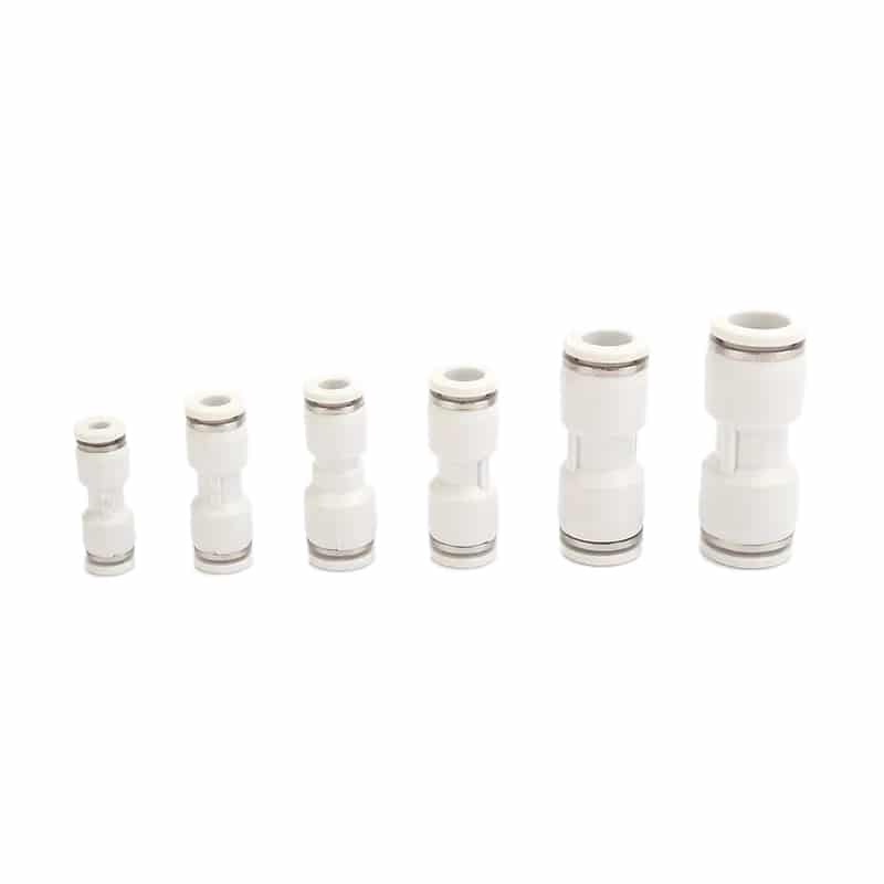
The PU straight-union family can simplify an in-line tube connection, but its exact tube and service limits still need to be checked against the selected part number.
How Should the Tube Be Routed and Supported?
Support the tube so the fitting is not used as a clamp, hinge, or structural brace. SMC warns against external force on push-in fittings and states that piping should be supported separately; this matters at elbows, reducers, manifolds, and branches where tube weight or motion produces leverage (SMC, accessed 2026).
Maintain the tube manufacturer’s minimum bend radius and leave enough straight tube at the connector for axial entry. Prevent these loads:
- tight bends that pull continuously across the collet;
- unsupported vertical drops and heavy hose bundles;
- repeated rubbing against guards, cable trays, or moving machine members;
- short, taut runs between vibrating components;
- Y-branches whose combined tube weight twists the branch fitting;
- heat exposure that softens the tube near the seal;
- washdown jets or chemicals outside the fitting and tube ratings.
Where motion or vibration cannot be removed, add suitable supports, guides, service loops, or a connector designed for the duty. Do not cable-tie the tube so tightly that it becomes oval.
How Do You Test the Joint Without Inventing a Universal Pressure Rule?
Pressurize and test only to the values and sequence approved for the machine, tube, fitting, and applicable standard. ISO 4414 covers pneumatic-system safety for machinery, but its public scope does not establish a universal “1.5 times pressure for five minutes” rule for every push-in connection (ISO 4414:2010, 2010).
The responsible engineer or approved commissioning procedure should define test medium, pressure, ramp rate, stabilization time, hold time, permissible leakage, guarded area, and acceptance record. Manufacturer proof-pressure data may be useful, but it is not permission to proof-test an assembled machine at that value.
For an approved soap-solution test, use a leak-detection fluid compatible with the fitting, tube, seal, port, and surrounding equipment. Apply it to one interface at a time and watch for persistent bubble growth. Clean the area afterward according to the product instructions. Do not use an open flame.
For a pressure-decay test, isolate a known volume, let temperature stabilize, record starting and ending pressure with calibrated instruments, and control all intentional consumers. A pressure decrease confirms leakage across the test boundary. However, it does not identify which component leaked. The pressure-decay leak-rate calculator can estimate leakage when the known volume and test conditions are valid.
Pressure-decay test is a leakage measurement in which a safely isolated known volume is monitored for pressure change over a defined time after temperature and operating conditions have stabilized.
How Can You Find and Prioritize Leaks in an Operating Plant?
Use a site-wide leak survey to locate candidates, then repair and verify one defined boundary at a time. DOE reports that compressed-air leaks can account for 20% to 30% of compressor output in poorly maintained systems, but that system-level range must not be presented as a fitting-only loss rate (U.S. DOE Compressed Air Tip Sheet #3, 2004).
Acoustic cameras and ultrasonic detectors can help find leaks while machinery is running, especially where ambient noise masks an audible hiss. Fluke describes acoustic imaging as a method for visualizing compressed-air leaks, but the image still needs confirmation at the actual tube, thread, seal, or body interface (Fluke ii900, accessed 2026).
Prioritize by estimated loss, production impact, safety access, repair difficulty, and recurrence history. Record the asset, location, pressure, detection method, suspected interface, repair, replacement part, and post-repair verification. A large header leak may deserve attention before many small fitting leaks, while a smaller leak on a critical actuator may rank higher because it causes unstable motion.
The calculator expresses the economic screen as:
Annual leak cost = estimated leak flow × compressor specific power × operating hours × electricity price
Treat the result as an estimate. Hole geometry, pressure, compressor controls, demand profile, and measurement quality all affect the answer. The pressure-drop troubleshooting guide helps separate true leakage from undersized tube, restricted valves, clogged filters, and normal peak demand.
How Do You Diagnose a Leak That Returns?
A recurring leak calls for root-cause separation, not a shorter replacement interval. DOE’s 20% to 30% system-loss range shows why recurrence matters economically, while the assembly approach in ISO 14743 means the tube, fitting, support, environment, and installation process all belong in the review (DOE, 2004; ISO, 2021).
Use the leak location to choose the branch:
- Leak at the collet: isolate, remove, and inspect tube cut, scratches, tooth marks, ovality, contamination, tube specification, insertion depth, and side load.
- Leak behind the fitting hex: verify the male and female thread forms, port condition, engagement, torque method, and approved thread sealant or sealing washer.
- Leak from the body: inspect for impact, stress, cracking, chemical attack, thermal exposure, corrosion, and an exceeded rating.
- Leak only during motion: inspect tube routing, vibration, moving-machine contact, bend radius, and repeated tension.
- Tube releases: remove the assembly from service and investigate the fitting series, tube OD and hardness, insertion, gripper damage, pressure excursions, and external load.
Tube-side leak is leakage at the push-in sealing interface where the fitting’s O-ring contacts the outside surface of the inserted tube. It is distinct from a threaded-port leak or a cracked fitting body.
Replace parts by condition and documented cause. There is no defensible universal rule that all push-in fittings must be replaced after a fixed number of years or cycles. Inspection frequency should reflect consequence, duty cycle, vibration, environment, historical failures, and the machine’s approved maintenance plan.
Installation Acceptance Checklist
A defensible handover record should prove compatibility, preparation, insertion, support, and verification. ISO 14743 treats the tube and fitting as a complete assembly. OSHA separately requires control of stored pneumatic energy before servicing. Both boundaries belong on the acceptance sheet (ISO, 2021; OSHA, accessed 2026).
- Exact fitting series and part number recorded
- Tube OD, material, hardness, pressure, temperature, and media compatibility verified
- Male and female thread forms confirmed where a threaded port is used
- Hazardous energy isolated, stored energy controlled, and isolation verified
- Tube cut square with the specified cutter
- Tube sealing length free from scratches, ovality, debris, and previous grip damage
- Manufacturer insertion depth or internal stop reached
- Light pull check passed
- Bend radius, straight entry, support, vibration, and moving clearance accepted
- Approved leak test completed at the defined conditions
- Leak location, corrective action, and post-repair verification recorded
Frequently Asked Questions
Can I reuse tubing after removing it from a push-in fitting?
Reuse it only if the manufacturer permits it and the reinstalled sealing length is undamaged. SMC says to cut off a chewed portion before reuse. After isolation, inspect for grip marks, scratches, flattening, and contamination, then recut squarely. If the remaining tube cannot meet routing or insertion requirements, replace it.
Can I use thread-seal tape to stop a leak at the collet?
No. Thread-seal tape belongs only where the exact threaded connection permits it; it cannot repair the tube-to-O-ring interface. A collet leak requires safe isolation and inspection of tube size, material, cut, surface, insertion depth, support, and fitting condition. Keep loose tape fragments out of pneumatic valves and actuators.
How far should the tube enter a push-in fitting?
Push it to the fitting’s internal stop or the insertion depth published for that exact series. Parker’s PLP demonstration shows tubing inserted until it bottoms, while SMC requires secure full insertion followed by a light pull. Do not copy one brand’s depth to another fitting; mark the catalog depth when provided.
Is a pull test enough to prove the connection is leak-free?
No. A light pull confirms retention, not sealing or pressure integrity. The O-ring may still leak because of a scratch, angled cut, contamination, incompatible tube, or side load. Complete the pull check, routing inspection, and approved leak test. Record the test conditions and verify the repaired interface afterward.
How often should push-in fittings be replaced?
There is no universal calendar interval. Base inspection and replacement on the fitting manufacturer’s instructions, application consequence, pressure and temperature exposure, vibration, chemicals, tube movement, leak history, and verified condition. DOE’s 20% to 30% figure applies to poorly maintained compressed-air systems overall, not to fitting life or replacement timing.
Sources
The evidence set prioritizes standards, workplace-safety rules, manufacturer installation instructions, and compressed-air efficiency guidance. Product-specific limits and actions remain tied to the named series. No cited source is used to support a universal fitting replacement interval or a universal pressure-test multiplier.
- ISO 14743:2021, Pneumatic fluid power, push-in connectors for thermoplastic tubes, scope for complete connector assemblies using 3 mm through 16 mm tube outside diameters. Retrieved 2026-07-14.
- ISO 4414:2010, Pneumatic fluid power, general rules and safety requirements for systems and their components, machinery pneumatic-system safety scope. Retrieved 2026-07-14.
- OSHA 29 CFR 1910.147, control of hazardous energy, stored-energy control and verification before servicing. Retrieved 2026-07-14.
- SMC, tubing installation and piping precautions, right-angle cutting, full insertion, light pull check, damaged-tube removal, and external-force precautions. Retrieved 2026-07-14.
- U.S. DOE, Compressed Air Tip Sheet #3, system-level 20% to 30% leak-loss context, common leak locations, and leak-program guidance. Retrieved 2026-07-14.
- Fluke ii900 Sonic Industrial Imager, acoustic visualization of compressed-air leaks; not used as a component rating source. Retrieved 2026-07-14.
- Parker video, How to Use Prestolok PLP Composite Fittings, visual demonstration of bottoming the tube and operating the release collet; not used to transfer Parker ratings to other series. Retrieved 2026-07-14.
Jason Tan’s credentials are carried by the page author system. Site ownership and technical scope are described on the About page, and readers can submit corrections through Contact.