

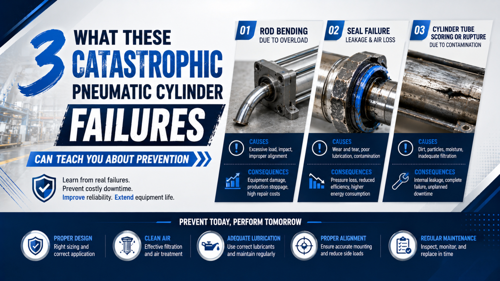
A catastrophic pneumatic cylinder failure is a loss of motion, force, sealing, guidance, or restraint with consequences severe enough to threaten people, tooling, product, or the machine. It rarely begins with one dramatic event. A force margin narrows, a seal or lubricant leaves its qualified temperature range, or a mounting joint starts to move.
These three scenarios are engineering reconstructions, not claims about named customer incidents. Each combines documented component behavior with a plausible failure chain. Their purpose is to show what evidence would confirm the mechanism, which early signals matter, and where a prevention barrier should interrupt the sequence.
Key Takeaways
- SMC publishes magnetic holding force by cylinder size, not as one universal value.
- Low-temperature reliability depends on the complete cylinder, grease, air quality, sensors, and seals.
- Press speed does not define the vibration spectrum at a cylinder mount.
- Preserve the as-found condition before adjusting, retightening, or replacing failed parts.
Why Can Minor Degradation Become a Catastrophic Failure?
ISO 4414:2010 is a 38-page pneumatic-system safety standard covering design, construction, installation, adjustment, operation, maintenance, reliability, and environmental considerations. Its system scope is the central lesson: a cylinder fault becomes catastrophic when several independent barriers fail to detect, contain, or safely stop the developing condition (ISO 4414:2010).
“Catastrophic” describes consequence, not a special component failure mode. The same coupling slip can be a recoverable stoppage on an unloaded transfer axis or a severe collision where the carriage carries fragile tooling. Severity depends on stored energy, load behavior, access to the hazard zone, stopping distance, and the machine’s response to a position discrepancy.
A useful failure reconstruction separates six stages:
- Latent weakness: inadequate force margin, an unqualified material, a flexible bracket, or missing fault detection.
- Applied stressor: acceleration, low temperature, contamination, vibration, shock, or maintenance disturbance.
- Margin loss: coupling capacity, seal elasticity, lubrication, joint preload, or guide alignment deteriorates.
- Detectable symptom: position error, leakage, slow response, fretting, noise, or changing vibration appears.
- Functional failure: the cylinder no longer reaches, holds, guides, seals, or stops the load as intended.
- Hazardous consequence: uncontrolled motion, collision, dropped load, damaged tooling, or personnel exposure occurs.
This sequence prevents a common root-cause mistake. The component found broken after the event is not automatically the initiating cause. A bent mount may have started as misalignment, lost preload, an impact, or overload created elsewhere in the mechanism.
For a control-system perspective, the related ISO 13849 pneumatic safety-circuit guide explains how risk reduction differs from ordinary cylinder position control.
How Can a Magnetic Coupling Lose Its Force Margin?
SMC’s CY3B catalog lists magnet holding forces from 19.6 N at 6 mm bore to 2,256 N at 63 mm bore. That wide model-specific range proves that a magnetic rodless cylinder must be checked against its exact holding-force rating, payload, acceleration, orientation, guide resistance, and operating condition (SMC CY3B Catalog).
Failure reconstruction 1: the carriage no longer follows the piston
Magnetic decoupling is relative movement between the internal piston and external carriage after the required transfer force exceeds the available magnetic holding force. In a magnetic rodless cylinder, compressed air moves the piston while magnets transfer motion through the nonmagnetic tube wall to the carriage.
Permanent demagnetization is not required for decoupling. A heavier payload, increased acceleration, an obstructed carriage, guide misalignment, hose drag, impact, or an operating temperature outside the product rating can consume the available margin. Treat an external magnetic field as a cause only when the field, orientation, distance, duration, magnet specification, and manufacturer limit are documented.
| Evidence | What it can establish | What it cannot establish alone |
|---|---|---|
| Piston indication differs from carriage position | relative motion occurred | why coupling capacity was exceeded |
| Dynamic pressure at both cylinder ports | pneumatic driving force during motion | magnetic holding force |
| Carriage breakaway or guide-drag measurement | external resistance changed | magnet condition |
| Exact model and catalog holding force | rated coupling limit | actual force margin under every transient |
| Temperature and nearby equipment history | an environmental stressor existed | irreversible demagnetization |
A sensor that detects the internal piston can report arrival even when the external carriage has not reached the same coordinate. On a consequence-critical axis, independent carriage or load verification may therefore be necessary. That decision belongs in the machine risk assessment, not in a generic cylinder rule.
Prevention starts with a documented force budget. Record the exact model, holding force, moving mass, process load, orientation, acceleration profile, guide resistance, temperature, and expected obstruction cases. Commission the axis at the worst approved recipe and verify that the machine detects a piston-to-carriage discrepancy before a collision.
Position disagreement is often a better early warning than a magnetic-field reading. A field measurement without controlled probe geometry and a healthy reference can be ambiguous. By contrast, a growing difference between commanded motion, piston indication, and carriage position directly exposes lost motion transfer.
For the force-transfer physics and recoupling limits, see the magnetic coupling break-away guide. The cylinder sensor fault-isolation guide covers electrical and magnetic signal faults separately.
How Can Cold Conditions Disable a Pneumatic Cylinder?
SMC’s -XB7 cold-resistant option is rated from -40 to 70°C and changes both seal material and grease. It also calls for dry air to prevent moisture freezing and lists model-specific restrictions. Cold reliability is therefore a complete configuration problem, not a simple choice between NBR and silicone (SMC Cold-Resistant Cylinder).
Failure reconstruction 2: leakage and drag rise during a cold start
Cold-start failure is a loss of acceptable motion, sealing, or control when an assembly begins operating at its lowest stabilized temperature. Suppose an outdoor cylinder moves slowly after a long idle period, then develops leakage or fails to reach position. Four mechanisms can produce that symptom:
- condensed water freezes in a pilot passage, valve, silencer, tube, or cylinder port;
- a seal compound stiffens and cannot follow its dynamic sealing surface;
- grease viscosity and boundary friction increase breakaway resistance;
- a switch, tube, fitting, regulator, or accessory falls outside its own temperature rating.
Do not identify “brittle NBR” from temperature alone. Parker explains that elastomers lose elasticity as temperature falls and uses temperature-retraction testing such as TR10 to evaluate low-temperature function. The same handbook also notes that silicone has good cold flexibility but poor wear resistance and is mainly suitable for static applications (Parker O-Ring Handbook).
That distinction matters in a pneumatic cylinder. Rod and piston seals are dynamic interfaces. Compound formulation, seal profile, lubricant, pressure, speed, surface finish, media, gland geometry, and cycle history all affect whether a material works. A generic material-family temperature table cannot approve a replacement seal.
Collect measurements before the equipment warms:
- ambient, cylinder body, valve, tube, and enclosure temperatures;
- pressure dew point at the relevant pressure and sampling location;
- dynamic pressure at both cylinder ports during the failed stroke;
- leakage location, carriage or rod position, and direction of motion;
- breakaway behavior and cycle time from cold start through warm operation;
- complete model codes, seal option, grease, tube, switch, and accessory ratings.
If response improves as the assembly warms, temperature is correlated with the symptom, but the mechanism is still unresolved. Ice, grease, elastomer stiffness, electrical behavior, and thermal misalignment need different corrective actions.
Effective prevention defines the lowest credible component and air temperatures, keeps pressure dew point below the coldest internal point with a documented margin, selects a complete cold-rated assembly, and tests the machine after its longest expected cold soak. Heating or insulation may help, but it must not create an uncontrolled surface temperature or mask wet compressed air.
For more detail, the cold-weather pneumatic failure guide covers dew point, winter commissioning, and component registers.
How Does a Mounting Joint Lose Preload Under Vibration?
IEC separates sinusoidal vibration testing in IEC 60068-2-6 from broadband random vibration testing in IEC 60068-2-64. Those two standards show why press strokes per minute cannot define the vibration environment at a cylinder mount. Frequency content, direction, amplitude, fixture response, and test severity must be measured or specified (IEC 60068-2-6; IEC 60068-2-64).
Failure reconstruction 3: a cylinder mount begins to move
Joint preload is the clamping force created when a fastener is tightened. A correctly clamped mounting joint transfers external shear through friction between its contact surfaces. If vibration, bracket flexure, impact, embedding, poor contact, or installation error reduces that force enough for slip to begin, the fastener can experience alternating shear and rotation. Movement then accelerates fretting, hole wear, preload loss, and misalignment.
Machine event rate is only one clue. A press running at a fixed stroke rate can excite frame modes and bracket resonances at other frequencies. Measurements taken on the press base do not necessarily describe the response at the cylinder mounting face.
NASA RP-1228 covers fastener torque, fatigue loading, washers, locking methods, and loads on fastener groups. It supports an engineered joint review, but it does not justify a universal rule that one washer, adhesive, or nut will survive every vibration spectrum (NASA Fastener Design Manual).
Evidence of joint movement can include:
- shifted witness marks or a changed nut position recorded against the installation baseline;
- polished contact patches, fretting debris, or red oxide;
- elongated holes, displaced washers, or bracket paint cracking;
- different vibration response at the base and cylinder mount;
- recurring alignment or side-load symptoms after retightening;
- damaged threads, bearing surfaces, or mounting faces.
Do not retighten first and photograph later. Breakaway torque after a joint has moved is not the original assembly preload, and retightening can erase the nut position, interface gap, and debris pattern needed to reconstruct the load path.
Prevention combines a stiff and correctly aligned mounting structure, fastener grade and engagement approved for the design, controlled installation, a qualified locking method, accessible witness marks, and a vibration acceptance test representative of the installed environment. Inspection intervals should follow observed stability and consequence, not an invented universal cycle count.
For measurement strategy and event-rate limits, use the high-speed stamping vibration guide. If a fracture has occurred, the tie-rod and mount fatigue analysis guide explains evidence preservation and fracture classification.
Evidence Preservation Before Root-Cause Analysis
NASA describes fatigue fracture in three stages: initiation, propagation, and final rupture. Evidence from those stages can coexist on one fracture face, while cleaning, grinding, matching surfaces, or running the machine again can destroy the origin. Preserve the as-found condition before attempting a component-level explanation (NASA RP-1291).
Safety comes first. Apply the site’s energy-control procedure, isolate pneumatic and other energy sources, relieve or restrain stored energy, support gravity loads, and verify isolation. Do not preserve evidence at the expense of exposing personnel to unexpected motion.
Once safe, create an evidence package:
- photograph the full machine, load path, cylinder, guides, mount, tubes, valves, sensors, guards, and failed position;
- record the last normal cycle, first symptom, alarms, controller states, pressure, temperature, recipe, load, and recent maintenance;
- mark the location and orientation of each fastener, seal, bracket, fracture half, and connector before removal;
- retain displaced parts, debris, grease, contamination, damaged seals, and comparison parts from unaffected positions;
- preserve PLC events, condition-monitoring trends, vibration data, maintenance records, torque records, and product certificates;
- document every action taken after the stop, including pressure relief, manual movement, adjustment, cleaning, and part replacement.
Separate observations from conclusions. “Carriage stopped 18 mm short” is an observation. “Magnet weakened” is a proposed mechanism. “External field caused irreversible demagnetization” is a root-cause statement that needs additional evidence.
In our experience reviewing pneumatic applications, the most useful evidence often comes from the first safe photographs and time-aligned machine records. A replacement cylinder can restore production, but it cannot recreate a moved witness mark, an undisturbed fracture face, cold-start pressure, or the controller state that existed before shutdown.
Use the separate side-loading guide to distinguish actuator damage from a machine load-path problem.
Prevention Barriers Across the Three Failure Chains
ISO/TR 14121-2:2012 is a 38-page guide to machinery risk assessment methods and risk-reduction measures under ISO 12100. A useful prevention plan therefore combines design, detection, maintenance, and safe-state controls. No single inspection, sensor, seal material, or locking device can cover all three failure chains (ISO/TR 14121-2:2012).
| Failure chain | Design barrier | Detection barrier | Maintenance barrier | Safe-state barrier |
|---|---|---|---|---|
| Magnetic coupling margin | model-specific force budget and guide review | independent carriage or load verification where risk requires it | trend position disagreement and guide drag | stop before collision after disagreement |
| Cold sealing and response | complete cold-rated configuration and dry-air specification | temperature, dew point, pressure, cycle-time, and leakage trends | pre-winter inspection and controlled cold-start test | inhibit motion outside approved conditions |
| Mounting-joint movement | stiff aligned bracket and engineered fastener system | witness marks and vibration baseline at the mount | inspect by condition and consequence | detect abnormal motion before detachment |
A barrier needs an owner, acceptance limit, test method, response, and record. “Inspect regularly” is not a control until the team defines what to inspect, how to measure it, what constitutes failure, and what happens when the limit is exceeded.
Monitor the variable closest to lost function. A gauss reading may help a magnetic investigation, but carriage disagreement measures failed motion transfer. Ambient temperature matters, but cold-start pressure, leakage, and travel time reveal actual pneumatic response. Frame vibration matters, but mount movement exposes loss of joint integrity.
Return-to-Service Criteria After a Serious Failure
OSHA 29 CFR 1910.147 requires hazardous stored or residual energy to be relieved, disconnected, restrained, or otherwise rendered safe, with isolation verified before servicing. It also requires the work area and equipment to be checked before energy is restored. A repaired cylinder alone is not sufficient return-to-service evidence (OSHA 1910.147).
Use the site’s authorized safety and commissioning procedures. A technical release should answer these questions:
- Was the failed function identified? State whether the loss involved force transfer, sealing, guidance, mounting integrity, sensing, cushioning, or control.
- Was the initiating cause supported by evidence? Distinguish confirmed findings, contributing conditions, and unresolved hypotheses.
- Was the complete damage boundary inspected? Include guides, brackets, valves, tubes, sensors, tooling, guards, stops, and the machine frame.
- Does the corrective action remove or control the cause? A larger cylinder does not correct binding; a new seal does not remove wet air; fresh bolts do not stiffen a resonant bracket.
- Were safety functions revalidated? Confirm protective stops, load restraint, guards, interlocks, position discrepancy detection, and safe exhaust behavior as applicable.
- Was commissioning staged? Start without exposed personnel or valuable workpieces, then progress through reduced load, speed, and cycle rate under controlled observation.
- Was a new baseline recorded? Capture pressure, position, leakage, cycle time, temperature, vibration, witness marks, and approved settings for future comparison.
Do not hide an unresolved mechanism behind a shortened inspection interval. More frequent checks can reduce exposure while analysis continues, but they do not convert an unknown failure mode into a controlled design.
Pneumatic Cylinder Failure Prevention FAQs: What Should Teams Ask?
Parker uses TR10 as one low-temperature evaluation method, SMC rates magnetic holding force by model, and IEC separates sinusoidal from random vibration testing. Those three examples support the same rule: prevention limits must be tied to the exact component, test method, installation, and consequence rather than a universal interval or material claim.
Are these three named customer incidents?
These are not named customer incidents. They are engineering failure reconstructions built from documented component behavior and accepted investigation principles. No company, loss amount, downtime figure, or laboratory result is attributed to them. Use the scenarios to build an evidence plan, then base any real root-cause statement on the affected machine’s records, measurements, parts, and approved procedures.
Does magnetic decoupling prove that the magnets were demagnetized?
Magnetic decoupling does not prove demagnetization. It shows that required transfer force exceeded available holding force at that moment. Excess payload, acceleration, impact, guide drag, obstruction, temperature, or magnet condition can contribute. Confirm the model rating, piston and carriage positions, load, pressure, guide resistance, and environmental history before naming irreversible demagnetization as the cause.
Should silicone automatically replace NBR in a cold pneumatic cylinder?
Silicone should not automatically replace NBR. It can offer good low-temperature flexibility, but Parker notes its poor wear resistance and primary suitability for static applications. Dynamic cylinder sealing also depends on compound formulation, profile, gland, lubricant, media, pressure, speed, and surface. Select the manufacturer’s qualified cold configuration rather than substituting a material family by temperature alone.
Is retightening loose cylinder-mount bolts enough?
Retightening alone is not enough. It may restore clamp temporarily while leaving bracket flexure, misalignment, damaged threads, elongated holes, poor bearing surfaces, or an unsuitable locking system unchanged. Preserve the as-found joint, identify why preload was lost, inspect the complete load path, and verify the corrected assembly under the measured or specified vibration environment.
How should preventive inspection intervals be selected?
Set intervals from consequence, duty, environment, manufacturer requirements, commissioning data, and observed degradation rate. Increase inspection frequency while evidence is limited, then revise it using position, leakage, pressure, temperature, vibration, and joint-condition trends. A universal quarterly, annual, or cycle-count rule is not defensible unless the exact product and application documentation establishes it.
Sources and technical references
- ISO 4414:2010, pneumatic-system safety requirements across design, installation, operation, and maintenance. Retrieved 2026-07-27.
- SMC CY3B Catalog, model-specific magnetic holding force, speed, bore, stroke, and precautions. Retrieved 2026-07-27.
- SMC Cold-Resistant Cylinder Specifications,
-XB7temperature range, low-nitrile seals, cold-resistant grease, dry-air requirement, and restrictions. Retrieved 2026-07-27. - Parker O-Ring Handbook, low-temperature elasticity, TR10 testing, compound limits, and dynamic-seal considerations. Retrieved 2026-07-27.
- IEC 60068-2-6, sinusoidal vibration testing. Retrieved 2026-07-27.
- IEC 60068-2-64, broadband random vibration testing. Retrieved 2026-07-27.
- NASA Fastener Design Manual, RP-1228, fastener loading, torque, fatigue, washers, and locking methods. Retrieved 2026-07-27.
- NASA Fracture Control Handbook, RP-1291, fatigue-fracture stages and evidence interpretation. Retrieved 2026-07-27.
- ISO/TR 14121-2:2012, machinery risk-assessment methods and risk-reduction examples. Retrieved 2026-07-27.
- OSHA 1910.147, hazardous-energy control, stored-energy treatment, verification, and restoration requirements. Retrieved 2026-07-27.