

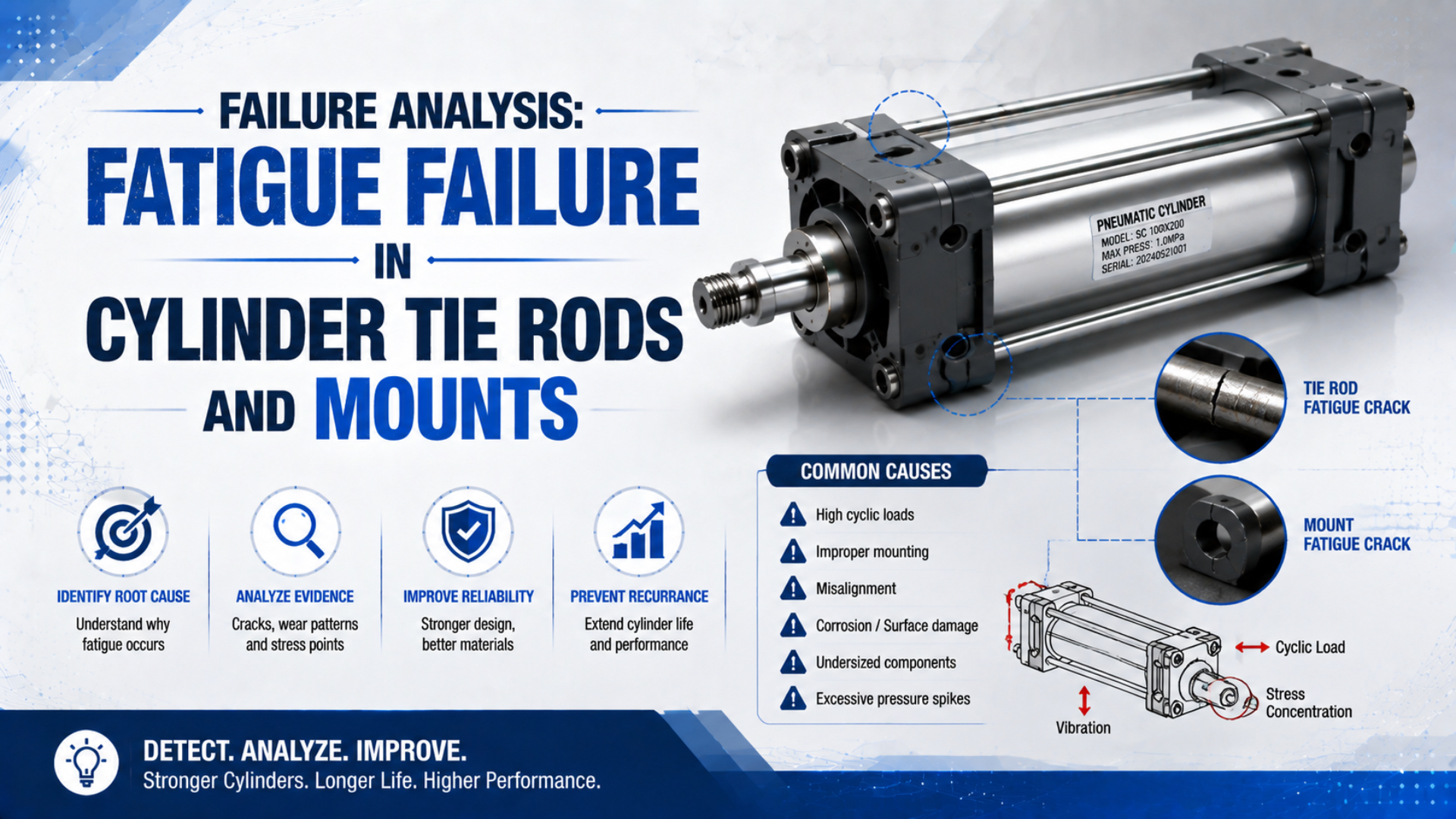
Fatigue failure is progressive crack initiation and growth under repeated or fluctuating stress, followed by final rupture when the remaining section can no longer carry the load. In cylinder tie rods and mounts, cycle count alone cannot diagnose it. The investigation must connect the fracture origin to a specific load path and service condition.
The practical question is not, “How many cycles should this part last?” It is, “What stress range acted at this specific origin, and why was that stress present?” The answer may involve pressure cycling, lost preload, installation misalignment, an unsupported side load, mount movement, corrosion, or several mechanisms acting together.
Key Takeaways
- NASA divides fatigue fracture into 3 stages: initiation, propagation, and final rupture.
- Preserve both fracture halves and the as-found joint before cleaning or retightening anything.
- Reconstruct pressure load, preload condition, bending, alignment, and mount reactions separately.
- Select NDT by material, crack location, and procedure limitations.
Publisher information and contact details are available on the About Us page.
Failure Analysis Starts With Evidence Preservation
NASA describes fatigue fracture as a 3-stage process of initiation, propagation, and final rupture. The fracture face may therefore contain evidence from different periods of service, but cleaning, grinding, matching broken halves, or running the machine again can destroy that evidence before an analyst identifies the origin (NASA RP-1291, 1993).
Fracture origin is the point or small region where crack initiation began. Preserve it with the surrounding material, deposits, and mating components. A laboratory may need the unaltered surface to distinguish machining damage, corrosion, fretting, material discontinuities, and service loading.
First make the equipment safe. Follow the site’s energy-control procedure, isolate pneumatic and other energy sources, bleed stored pressure, restrain gravity loads, and verify isolation. OSHA 29 CFR 1910.147 includes pneumatic energy and requires stored or residual energy to be relieved, disconnected, restrained, or otherwise rendered safe during covered servicing (OSHA 1910.147).
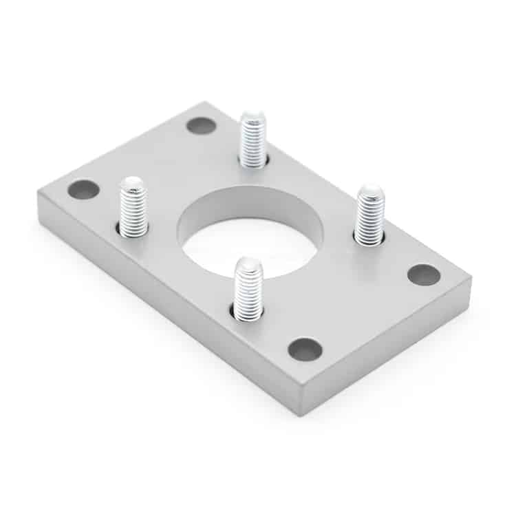
A fixed mounting plate creates several possible evidence locations: stud threads, mounting holes, contact faces, and the supporting frame.
Preserve the as-found condition before disassembly:
- Photograph the complete cylinder, load, guides, brackets, hoses, and guards from several directions.
- Mark each tie rod, nut, washer, mount, pin, spacer, and fracture half so its location and orientation remain known.
- Record witness-mark movement, end-cap gaps, fretting, corrosion, paint cracking, displaced washers, loose hardware, and contact marks.
- Record the failed stroke position, motion direction, payload, pressure, speed, recent maintenance, and any unusual event.
- Protect fracture faces from contact and moisture. Do not wire-brush, blast, pickle, grind, or coat them.
- Retain mating hardware and comparison parts from unaffected positions whenever the investigation plan allows.
In our experience, the most valuable photograph is often taken before anyone reaches for a wrench. Nut position, polished interfaces, red oxide, debris, and uneven gaps can explain how load moved through the joint. We found that cleaning and retightening too early can erase the only record of that movement.
Is the Fracture Fatigue Failure, Overload, Corrosion, or Joint Movement?
NASA notes that fatigue striations are associated with crack propagation and require high magnification, while the final rupture region may be ductile, brittle, or mixed. A smooth or banded fracture seen by eye is therefore not enough to declare fatigue, count cycles, or identify the initiating load (NASA RP-1291, 1993).
Classify observations as evidence, not conclusions:
| Observation | Possible explanation | What the observation does not prove |
|---|---|---|
| Crack begins at a thread root or machining mark | Local stress concentration or damaged surface | The nominal load was excessive |
| Concentric or curved progression marks | Progressive crack-front movement | One visible band equals one operating cycle |
| Ratchet marks from several origins | Multiple cracks joined during growth | The material was defective |
| Small progressive region with a large rough final region | Crack growth followed by final overload | The final event initiated the crack |
| Fretting or polished joint faces | Relative movement at a nominally clamped interface | Tie-rod torque was definitely too low |
| Corrosion products at the origin | Environment contributed to initiation or growth | Corrosion was the only cause |
| Necking or broad plastic deformation | Ductile overload is possible | No earlier fatigue crack existed |
The fracture is evidence. It is not yet the cause.
A fatigue conclusion needs an identified origin, progressive growth evidence, and a final ligament failure. Overload needs a load path compatible with the observed deformation. Corrosion-assisted cracking needs matching material, environment, and morphology. Joint movement needs compatible witness marks and a mechanical reason for lost clamp or applied shear.
Do not estimate remaining life from the visible crack face alone. ISO 12108:2018 describes controlled fatigue-crack-growth testing from a threshold stress-intensity range toward unstable fracture under stated specimen and loading conditions. A service component with unknown residual stress, geometry, environment, and load history does not reproduce that test automatically (ISO 12108:2018).
Reconstruct the Tie-Rod Stress Range From the Pressure Cycle
NASA’s Fastener Design Manual explains that a preloaded joint changes how an external tensile load is divided between increased fastener tension and reduced compression in the clamped parts. Pressure force cannot simply be divided by the number of tie rods unless joint stiffness, geometry, seating, and load distribution justify that model (NASA RP-1228, 1990).
Tie-rod preload is the tensile force established during controlled assembly before pressure is applied. Its purpose is to keep the clamped interfaces seated through the intended service load. Torque is one possible installation input for producing preload, but unknown friction prevents a wrench reading from proving the original clamp force.
Start with the ideal separating force on the pressurized end area:
Here, is the ideal end-separating force, is cylinder gauge pressure, and is the effective pressurized diameter. Use consistent SI units. The effective diameter must match the real pressure boundary; bore diameter is only a screening assumption when the end-cap geometry is unknown.
For a pressure range from to :
For a screening example, let and let pressure change from to . The ideal external force range is about 4.71 kN. That is not the range in each tie rod. Dividing by 4 would imply about 1.18 kN per rod only if the full external change entered the fasteners and the joint shared it equally. Pressure data establishes one input; it does not establish , preload retention, end-cap stiffness, or equal seating. Record the drawing source for , measure pressure at the cylinder, and preserve the assumptions beside the result.
If a joint model assigns a fraction of that external range to fastener load and distributes it across tie rods:
is a stiffness-dependent load fraction, not a universal constant. It depends on tie-rod and clamped-part stiffness, contact geometry, preload, seating, and whether the interface remains compressed. Unequal gaps, end-cap bending, damaged threads, or a loose rod can invalidate equal distribution.
Using the tensile stress area of the actual thread:
The alternating and mean nominal stresses are:
These equations organize the load history; they do not predict life by themselves. A qualified assessment still needs the real thread geometry, material and heat treatment, surface condition, residual stress, corrosion exposure, preload, stress concentration or fatigue notch factor, and applicable fatigue data. ISO 12107:2012 treats fatigue properties statistically at defined stress levels rather than as a universal cycle rating (ISO 12107:2012).
Pressure is only one load source. Add cushion and impact events, acceleration, cylinder weight, guide reactions, mount bending, frame movement, and misalignment in their correct directions. For example, the cylinder force calculator can screen pressure-generated force, but it cannot calculate tie-rod fatigue life or mount stress.
Keep pressure, bending, and impact separate.
The useful output is not one calculated stress. Build a load timeline that places pressure, position, speed, and external reaction beside each other. A mount may see its largest bending range during reversal or cushion entry even when the highest static pressure occurs elsewhere in the cycle.
Where Should You Look for the Crack Origin?
Parker requires piston-rod alignment to be checked in both extended and retracted positions, giving at least 2 machine states for the installation review. Its mounting guidance also says trunnion bearing blocks must be aligned and rigidly mounted so the trunnions are not subjected to bending moments (Parker Cylinder Safety Guide).
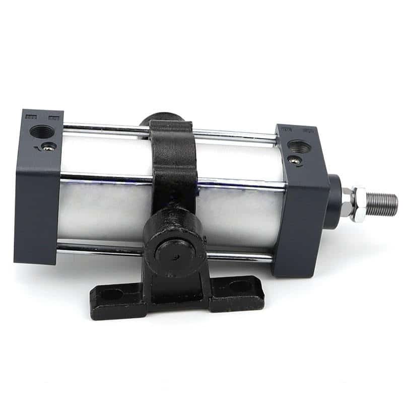
A trunnion mount should pivot about aligned pins. Frame distortion, bearing clearance, or pin-axis error can add bending that a pressure-only calculation misses.
For a tie rod, document the complete transition from the nut-bearing face through the engaged thread, first free thread, thread runout, plain shank, and end attachment. Potential origins include corrosion pits, damaged threads, sharp runouts, handling marks, galling, unintended bending, and local contact. The fracture origin must be matched to the actual feature, not selected from a generic list.
For a mount, inspect both the cylinder part and the supporting machine structure:
- mounting-hole edges, counterbores, spot faces, washers, and bolt-bearing surfaces; photograph hardware orientation and every contact mark before any disassembly begins;
- flange pilots, dowels, thrust keys, and evidence of interface slip;
- clevis and trunnion pins, bushings, lubrication condition, and pin-axis alignment;
- weld toes, weld terminations, heat-affected regions, and repaired areas; record where the origin sits relative to the weld profile and load direction;
- bracket section changes, cutouts, sharp internal corners, and corrosion traps;
- frame cracks, loose anchors, distorted plates, and guide misalignment through the full stroke.
Trace the crack back to its origin under magnification. Record the direction of growth and the position of the final rupture region. Then place that direction on the assembly drawing. A fracture face that indicates bending on a part intended for pure axial tension is a strong reason to investigate alignment, eccentricity, and joint movement.
The related cantilevered-cylinder deflection guide covers rod bending calculations. The tie-rod torque and longevity guide covers controlled preload and reassembly. Keep those calculations separate from the present fracture investigation.
Select NDT by Material and Crack Location
ASTM E1417/E1417M-21 applies liquid penetrant testing to nonporous materials and discontinuities open to the surface. ASTM E3024/E3024M-22a covers magnetic-particle detection of surface or slightly subsurface discontinuities in ferromagnetic materials. These are different capabilities, so material and expected crack location must be known before selecting a method (ASTM E1417; ASTM E3024).
| Method | Useful boundary | Important limitation |
|---|---|---|
| Visual examination | As-found position, deformation, corrosion, fretting, open cracks | Cannot exclude a small, hidden, or subsurface crack |
| Liquid penetrant | Surface-connected discontinuities in suitable nonporous materials | Does not establish depth and will miss closed or internal cracks |
| Magnetic particle | Surface and slightly subsurface discontinuities in ferromagnetic parts | Not applicable to non-ferromagnetic alloys; field direction affects detectability |
| Ultrasonic testing | Internal discontinuities when geometry, frequency, calibration, and procedure are suitable | Threads, small sections, rough surfaces, and complex geometry can limit interpretation |
| Eddy-current testing | Surface and near-surface examination of conductive materials with a qualified setup | Geometry, lift-off, conductivity, permeability, and reference standards affect the signal |
| Metallographic or SEM examination | Origin morphology, microstructure, deposits, and high-magnification fracture features | Usually requires laboratory preparation and may consume part of the evidence |
No single method covers every defect.
NDT must follow a written, applicable procedure with qualified personnel, suitable reference standards, calibrated equipment, surface preparation, coverage, acceptance criteria, and recorded results. A method name on a work order is not a procedure.
Inspect comparison locations, not only the visible break. A failed tie rod can leave the remaining rods overloaded, and one cracked mount can indicate that nominally identical corners experienced different stiffness or contact. The investigation plan should define which parts remain available for laboratory work and which must be returned to service.
Connect the Finding to the Real Load Path
Parker states that side-mounted cylinders rely on friction at the mounting surfaces and recommends thrust keys or dowels to resist the major load. It also requires aligned clevis pins and trunnion supports. These details show why a mount crack must be connected to interface slip, shear transfer, pivot geometry, and frame stiffness, not pressure alone (Parker U250/U250N).
Build a cause-and-evidence matrix before choosing corrective action:
| Suspected contributor | Evidence to seek | Corrective direction if confirmed |
|---|---|---|
| Pressure-cycle range | Port pressure, cycle states, pressure spikes | Correct circuit, pressure envelope, or joint design |
| Lost or uneven preload | Witness movement, gaps, fretting, hardware and assembly records | Restore with exact parts and the controlled OEM procedure |
| Misalignment | Extended, mid-stroke, and retracted measurements; wear direction | Realign cylinder, guide, coupling, and frame |
| Side-mounted interface slip | Polished faces, moved marks, bolt-hole bearing, missing key or dowel | Provide approved shear transfer and mounting preload |
| Trunnion or clevis bending | Pin wear, bearing alignment, support movement | Correct pivot geometry, bearings, support stiffness, and lubrication |
| End-of-stroke impact | Motion trace, cushion setting, damaged stops, mount vibration | Reduce entry energy or add a correctly sized stopping system |
| Corrosion-assisted initiation | Deposits at origin, environment records, material and coating evidence | Remove exposure path and select compatible protection or material |
| Manufacturing discontinuity | Origin at a material or machining feature, comparison-part evidence | Escalate supplier and process investigation with traceable samples |
One finding can have several contributors.
Consider a side-mounted cylinder with a crack growing from one mounting-hole edge. Normal pressure history does not clear the installation. If the contact face is polished, witness marks have shifted, and the specified thrust key is absent, the evidence may support repeated interface slip and bolt-hole bearing as the local load path. The corrective action would then address shear transfer, mounting preload, and frame stiffness. Merely installing a thicker bracket could leave the initiating movement unchanged. This is a hypothetical reasoning chain, not a diagnosis; each link still needs measured or photographed evidence from the actual machine.
Do not stop at the first plausible cause. A loose mount may be the result of frame movement, not the initiating event. A corrosion pit may mark the origin, but bending may have created the stress range that propagated the crack. A final impact may complete a fracture whose fatigue region grew over many earlier cycles.
For load-path correction, use the side-load mitigation guide and the broader cylinder mounting selection guide. If end impact appears in the evidence, review the cylinder cushioning method separately.
Decide Between Replacement, Redesign, and Escalated Analysis
ISO 12108:2018 spans crack-growth testing from the threshold stress-intensity range to the onset of rapid, unstable fracture. A discovered service crack has already changed the section and local stress field, so retightening, stop-drilling, grinding, or welding it without an approved engineering disposition does not restore the original validated condition (ISO 12108:2018).
Replace the affected tie rod, fastener, mount, or complete cylinder when the exact product instruction requires replacement, the crack exceeds an approved repair limit, material identity is uncertain, mating parts are damaged, or the assembly cannot be inspected and tested to defined criteria. Replace associated hardware when the failure redistributed load or the manufacturer’s procedure requires a set.
Redesign the load path when evidence shows the original architecture repeatedly imposes bending, interface slip, impact, or side load that the component was not meant to carry. A stronger fastener does not correct a flexible frame, skewed guide, missing thrust key, or trunnion subjected to bending.
Escalate to a qualified failure-analysis laboratory or responsible design authority when:
- the origin is unclear or has been damaged;
- the failure consequence is safety-critical or the same design remains installed on other machines;
- several mechanisms remain plausible;
- material, heat treatment, coating, or residual stress is disputed;
- a custom repair or weld is proposed;
- remaining-life or fleet-wide disposition is required;
- similar cracks appear in more than one component or machine, suggesting a common design, manufacturing process, operating environment, installation method, or maintenance contributor.
Suppose 2 nominally identical cylinders fracture at the same thread position on different machines. Replacing both rods may restore operation, but it does not answer whether the shared cause is thread geometry, material processing, assembly damage, end-cap bending, pressure transients, or installation practice. The investigation should preserve comparison rods, match model and lot records, compare the origins, review torque and lubrication instructions, and overlay the measured load histories. If the origins and evidence are materially alike, the disposition may need to cover the installed population rather than only the 2 failed units. That decision belongs to the responsible design authority with traceable laboratory and service evidence.
The corrective action should remove the cause represented by the origin, not merely replace the part that finally separated. If the origin is at a thread damaged during assembly, control the assembly process. If it is at a mount hole loaded in repeated bearing after interface slip, restore the intended shear path and frame stiffness.
Build a Return-to-Service Evidence Package
ISO 4414:2010 remains current after its 2021 confirmation and covers pneumatic-system hazards through design, installation, operation, and maintenance. OSHA 1910.147 separately requires hazardous-energy control during covered servicing. A replacement component and a successful no-load stroke are therefore only parts of a defensible return-to-service decision (ISO 4414; OSHA).
The release package should identify:
- machine, cylinder, complete model code, bore, stroke, mount, and serial or lot information;
- failed part position, orientation, material, dimensions, as-found photographs, and custody history for every retained sample from removal through laboratory examination and final storage;
- fracture origin, propagation direction, final region, and laboratory methods;
- pressure, load, position, speed, acceleration, cushion, and cycle-history evidence;
- tie-rod, nut, washer, pin, bushing, bracket, frame, guide, and coupling findings;
- root cause, contributing causes, excluded causes, remaining uncertainty, and the evidence supporting each decision;
- replacement parts, design changes, controlled assembly instructions, and tool records;
- static alignment, leakage, no-load, controlled-load, and production validation results;
- follow-up inspection trigger based on risk and the observed mechanism, including the method, coverage, responsible person, acceptance limit, and stop condition rather than a generic calendar interval.
Return pressurization must use a guarded, controlled test plan defined by the manufacturer, responsible engineer, applicable standards, and the lowest-rated component. Record dynamic pressure at the cylinder, not only the regulator setting. Verify the full stroke, mount movement, guide reaction, cushion entry, sensor function, leakage, and the machine’s acceptance criteria.
If the cylinder joint was disassembled, use exact torque and friction conditions from the current model-specific instruction. Do not infer torque from bore size or copy it from another series. The separate repair-versus-replace guide helps document the commercial and technical disposition after the root cause is known.
From our work, a good failure report lets another engineer reproduce the reasoning without seeing the broken part. It connects each conclusion to a photograph, measurement, trace, calculation, material record, or test. Statements such as “fatigue from vibration” are not enough unless the report identifies the origin, stress direction, vibration source, and corrective verification.
Cylinder Tie-Rod and Mount Fatigue Failure FAQs
NASA separates fatigue fracture into 3 stages, while ASTM distinguishes surface-connected penetrant indications from surface or slightly subsurface magnetic-particle indications in ferromagnetic parts. These boundaries answer the most common investigation questions: what proves fatigue, where to inspect, what a test can detect, and when a cracked component requires engineering escalation (NASA; ASTM).
Can the number of operating cycles prove a tie-rod fatigue failure?
No. Cycle count describes exposure, not the stress range, material, geometry, preload, environment, or failure mechanism. ISO 12107 treats fatigue properties statistically under defined test conditions. Confirm fatigue through the fracture origin and propagation evidence, then reconstruct the loads that acted at that origin rather than applying a universal cycle threshold.
Where do fatigue cracks usually start in a cylinder tie rod?
Inspect thread roots, the first free or first highly loaded thread, thread runout, section transitions, corrosion pits, and damaged surfaces, but do not assume one location. The true origin must be identified on the fracture and mapped back to the tie rod’s installed orientation, load direction, nut, end cap, and mating interfaces.
Can dye penetrant find every fatigue crack?
No. ASTM E1417 applies penetrant testing to discontinuities open or connected to the surface of suitable nonporous materials. It does not establish crack depth and cannot exclude a closed or fully internal crack. Material, surface condition, geometry, expected crack orientation, and a qualified written procedure determine whether penetrant is appropriate.
Should an unbroken tie rod be reused after another rod fractures?
Not automatically. The remaining rods may have carried redistributed load, and their threads, straightness, corrosion, or preload condition may be unacceptable. Preserve them for comparison, inspect them to the manufacturer’s criteria and investigation plan, and follow the exact replacement rules for the cylinder. Unknown history is not evidence of serviceability.
Is retightening enough when a mount shows fretting or a fatigue crack?
No. Fretting indicates relative movement but does not identify why it occurred. A fatigue crack changes the load-bearing section. Isolate the machine, preserve evidence, inspect the joint and frame, and determine whether preload, shear transfer, alignment, pivot geometry, impact, or structural flexibility caused the movement before approving replacement or redesign.
Sources and technical references
-
NASA RP-1291, Fractography Handbook of Spaceflight Metals. Evidence role: fatigue initiation, propagation, final rupture, and fracture-surface interpretation. Published 1993; retrieved 2026-07-19.
-
NASA RP-1228, Fastener Design Manual. Evidence role: preloaded-joint load sharing and fastener fatigue mechanics. Published 1990; retrieved 2026-07-19.
-
ISO 12107:2012. Evidence role: statistical planning and analysis of metallic-material fatigue data. Retrieved 2026-07-19.
-
ISO 12108:2018. Evidence role: controlled fatigue-crack-growth testing boundaries. Retrieved 2026-07-19.
-
Parker U250/U250N Pneumatic Tie-Rod Cylinders. Evidence role: alignment and mounting recommendations. Retrieved 2026-07-19.
-
Parker Cylinder Safety Guide. Evidence role: extended and retracted alignment checks, trunnion and clevis mounting boundaries. Retrieved 2026-07-19.
-
ASTM E1417/E1417M-21. Evidence role: liquid-penetrant testing scope and limitations. Retrieved 2026-07-19.
-
ASTM E3024/E3024M-22a. Evidence role: magnetic-particle testing for general industry. Retrieved 2026-07-19.
-
ISO 4414:2010. Evidence role: pneumatic-system general rules and safety scope. Confirmed 2021; retrieved 2026-07-19.
-
OSHA 29 CFR 1910.147. Evidence role: control of hazardous energy during covered servicing. Retrieved 2026-07-19.