

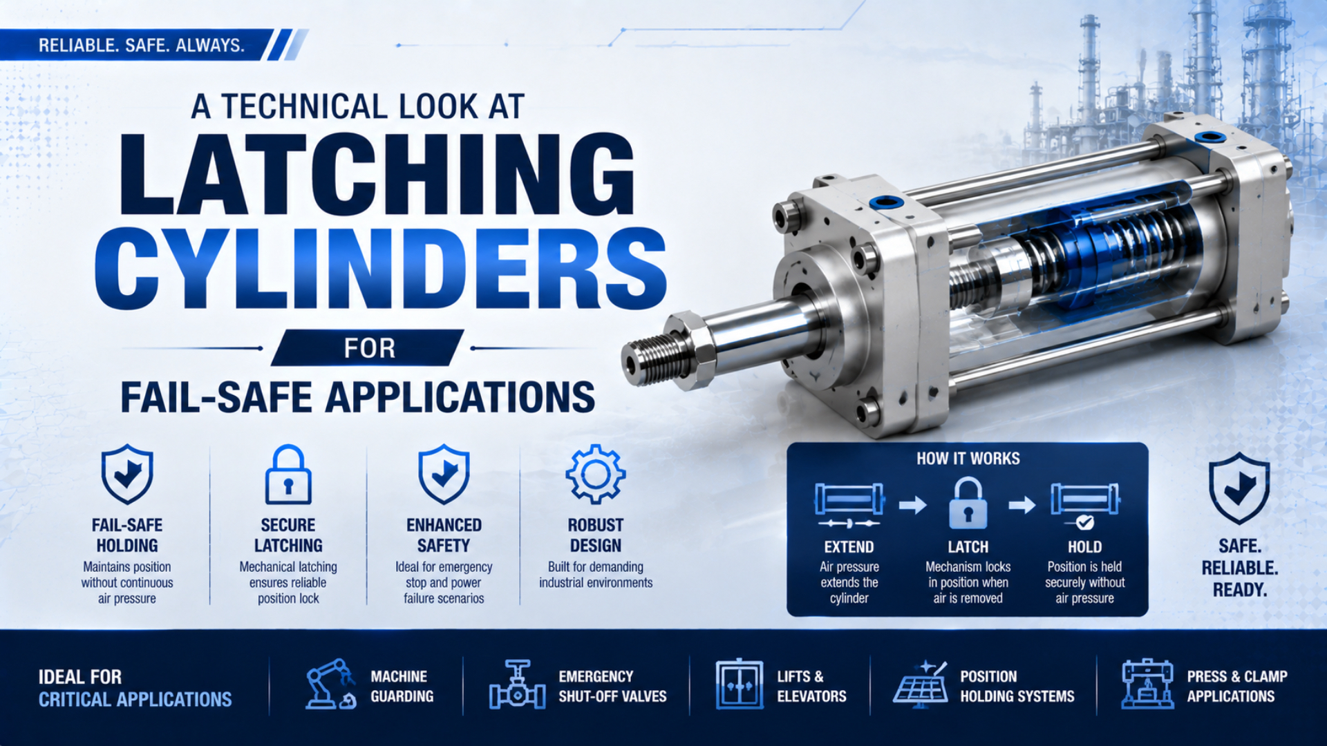
Latching cylinders use a mechanical feature to retain a defined position after their normal driving energy changes or disappears.
The feature helps, but it isn’t a complete safety function. Safe performance still depends on where the latch acts, what load it must restrain, how it releases, and what happens during restart.
That distinction matters because the U.S. Bureau of Labor Statistics recorded 756 fatal contact incidents in 2024, including events involving powered equipment and falling or suspended objects (BLS CFOI, 2026). Mechanical holding is valuable only when the device and complete safety function match the actual hazard.
Key Takeaways
- Parker’s End-Lock acts only at the fully retracted position.
- An any-position rod lock is a different device with different limits.
- Static holding and dynamic braking require separate ratings.
- “Fail-safe” must be demonstrated through risk assessment, circuit design, release sequencing, and validation.
What Is a Latching Cylinder, Exactly?
Parker’s pneumatic End-Lock uses multiple spring-loaded pins and engages only when the piston rod is fully retracted; removing cylinder air completes the mechanical lock (Parker End-Lock, 2025). In this article, latching cylinder means that end-position arrangement, not every cylinder fitted with a holding device.
Field Note from David Li
In our experience, the drawing should mark the safe position first. That single mark settles the product category quickly. I found the next question should be whether the device must hold a stopped load or arrest motion. Our team found the final check is recovery: what prevents movement when air returns and the latch releases?
Geometry carries the decision. Manufacturers normally build the latch into, or offer it as an option for, a specific cylinder family. Moving parts engage a machined feature at the designed endpoint. Once engaged, the load passes through the rod, lock parts, cylinder body, mounts, and frame.
That definition excludes several devices that are often placed in the same catalog conversation:
| Device | Where it can hold | What creates the hold | Main engineering question |
|---|---|---|---|
| End-position latching cylinder | One specified end position | Pins, dogs, hooks, or another positive mechanical feature | Has the piston reached the engagement position? |
| Rod lock or clamping unit | End or intermediate positions | A clamp grips the piston rod | Is the rod stopped, aligned, and within the static or dynamic rating? |
| Pilot-operated check or closed-center valve | Wherever trapped pressure balances the load | Blocked pneumatic flow | How much drift occurs through valves, seals, tubing, and fittings? |
| External mechanical restraint | One defined support position | Block, prop, pin, brake, or structural stop | Can the restraint carry the full hazardous load independently? |
Product naming is not a safety function. Endpoint hardware that reliably holds full retraction cannot protect an operator when the hazard occurs halfway through the stroke. Start with the required safe position, then decide whether an end latch, an any-position cylinder rod lock, or a separate restraint fits.
End-Position Latches Versus Any-Position Rod Locks
Festo lists up to 8,000 N of static holding force for its DNCKE cylinder with clamping unit, but that figure describes an any-position rod clamp rather than universal latching-cylinder capacity (Festo DNCKE, 2020). It is a separate device. End latches hold only at a registered endpoint.
Endpoint latches wait for a known geometric condition. Before pins or dogs can enter their mating feature, the piston must arrive and register correctly. That suits a “fully retracted and mechanically retained” state. It offers no intermediate-stroke protection, whereas rod locks clamp wherever motion stops under their approved direction, rod, pressure, and load limits. The rod-lock selection guide covers that separate duty.
Static holding differs from dynamic braking. Holding a stopped 1,000 N load is not equivalent to arresting it in motion; braking adds kinetic energy, stopping distance, heat, contact stress, and wear. A static rating cannot become an emergency-stop rating. Valve-based pneumatic check circuits are farther removed because they trap air rather than create a direct mechanical path, leaving leakage and stored-pressure hazards to manage.
What Happens When Air or Electrical Power Is Lost?
Parker states that removing air pressure completes the End-Lock’s mechanical locking process, while normal release requires pressure to return to the head end before the cap end (Parker End-Lock, 2025). That sequence shows why “spring engaged” alone is not a complete fault analysis.
Consider the whole transition, not just the final locked state:
- Approach: The piston moves toward the permitted latch position. Speed and cushioning must keep the end impact within the cylinder’s limits.
- Engagement: The piston reaches the mechanical registration point and the latch elements enter fully. A position switch may confirm piston location, but confirmation of the latch itself is stronger when available.
- Energy loss: Air or electrical power disappears. The mechanism must remain engaged while external force acts through the cylinder and mounting structure.
- Recovery: Supply returns, chamber forces are brought to the required state, and the latch releases only after the control system has prevented unintended motion.
What if power fails before the piston reaches the endpoint? The latch may never engage. A load reversal after engagement can also expose an overlooked force case. Meanwhile, the opposite chamber may hold compressed air, and a spring, counterweight, product, or process force may move the axis as soon as the latch releases. Both the pressure condition and mechanical condition must therefore be defined in the fault analysis.
When Can a Latching Cylinder Be Called Fail-Safe?
ISO 13849-1:2023 applies to safety-related control systems in high-demand and continuous operation across electrical, hydraulic, pneumatic, and mechanical technologies, but it does not prescribe the safety function or required Performance Level for a particular machine (ISO 13849-1, 2023). A latching cylinder can contribute to a safety function; it cannot inherit machine-level compliance by itself.
Position comes first. Risk reduction starts with ISO 12100 risk assessment: identify exposure, hazardous motion, credible severity, and the state that reduces risk. An end latch fits only when its reachable position matches that state. Then define control behavior, determine PLr, and evaluate the complete response. The ISO 13849 pneumatic safety circuits guide covers that method, while IEC 62061 projects should retain SIL terminology (IEC 62061, 2021). System-level pneumatic hazards remain within ISO 4414, alongside any more detailed type-C standard.
A defensible “fail-safe” claim needs four linked statements: the hazard is defined, the safe state is measurable, the latch stays within documented limits, and relevant faults have been validated. Missing any one calls for narrower wording such as “spring-engaged end-position holding.” During maintenance, automatic control remains separate from isolation. OSHA 29 CFR 1910.147 requires covered machinery to be isolated and residual energy made safe (OSHA 1910.147, 2026).
How Should Holding Force and Load Paths Be Checked?
Festo’s DNCKE data separates size-dependent static holding values up to 8,000 N from braking behavior, and Parker limits its End-Lock description to fully retracted locking (Festo DNCKE, 2020; Parker End-Lock, 2025). Selection must therefore follow the exact device rating and load case, not cylinder bore alone.
A useful load-case statement is:
Here, is the required restraining force in newtons. is the gravity component along the motion axis, is any external process force, is cylinder force acting in the hazardous direction, and covers only dynamic effects that the manufacturer permits the device to absorb.
This relationship organizes the load case; it doesn’t authorize an arbitrary safety factor. Selection margin comes from the risk assessment, standard, manufacturer rating method, load variation, and validation evidence. Use the Pneumatic Cylinder Force Calculator when pressure force acts in the hazardous direction, then add gravity, tooling, product, spring, counterweight, and process forces. Finally, trace the load through the lock, rod, cylinder body, mounts, fasteners, and frame. A weak bracket can defeat an adequately rated latch.
Before requesting a quotation, record:
| Required information | Why the supplier needs it |
|---|---|
| Exact safe position | Confirms whether one endpoint is sufficient |
| Static holding or dynamic braking | Determines whether energy absorption is part of the duty |
| Load magnitude and direction | Establishes the hazardous force case |
| Cylinder bore, rod, stroke, and mounting | Checks mechanical and dimensional compatibility |
| Pressure range and failure state | Defines engagement and release conditions |
| Speed at a possible demand | Supports stopping-distance and wear review |
| Required feedback | Identifies latch-engaged, latch-released, or piston-position sensing |
| Environment and cycle rate | Checks contamination, temperature, corrosion, and service limits |
Safe Release and Restart Logic
Festo warns that its clamping unit may be released only after piston forces reach equilibrium and that blocking both cylinder ports with a 5/3-way valve does not by itself provide safety (Festo DNCKE, 2020). The same principle applies to endpoint latches: release must not expose an unbalanced load.
Pressure restoration is a new operating event. Opening the latch before controlling chamber force, load, and command state can make the piston jump from the endpoint. Reset must not become a motion command, and missing latch feedback should inhibit the next hazardous cycle. Design the recovery sequence backward from the first safe motion, asking what must be true at every prior step until the machine is still de-energized. This catches a common blind spot: safe air loss followed by unsafe air restoration.
Mechanism-specific instructions control the final sequence. Parker calls for head-end back pressure before cap-end pressure, while another design may use a separate release port or manual tool. Don’t copy a generic sequence across product families.
Commissioning and Maintenance
ISO 13849-2:2012 remains the published validation standard while a replacement is under development; it calls for analysis and testing of safety functions, Categories, and Performance Levels (ISO 13849-2, 2012). A latching-cylinder installation therefore needs measured evidence from each installed machine.
Keep personnel clear. Commission in stages without exposed personnel. Confirm engagement and release first, then progress to representative and worst credible conditions. Record pressure, load, direction, speed, position, signals, feedback, movement after demand, and final state.
| Test | Evidence to record | Typical fault revealed |
|---|---|---|
| Endpoint approach | Speed, cushion setting, and confirmed latch position | Piston reaches the end but the latch doesn’t seat fully |
| Loss of air or power | Demand time, engagement feedback, and load movement | Tubing or valve behavior delays engagement |
| Static holding | Load, direction, duration, and measured displacement | Structure deflects or the device creeps |
| Release under controlled pressure | Chamber pressures and first motion | Unbalanced force causes a jump |
| Feedback disagreement | Controller response and restart inhibition | Sensor failure is accepted as a safe state |
| Manual recovery | Access method, tooling, restraint, and authorization | Recovery bypasses energy control or exposes personnel |
Inspection records should name the observed condition instead of saying only “lock OK.” Note fretting, galling, peening, burrs, ovality, corrosion, contamination, looseness, misalignment, delayed seating, or unstable feedback when present. Each symptom points to a different failure path. Add measured release pressure, engagement delay, displacement under load, sensor disagreement, and relevant fastener torque. Photographs taken from a repeatable angle make gradual damage easier to compare. If a measurement moves from its commissioning baseline, investigate before widening the acceptance limit. Static latches deserve this discipline even when they never brake a moving load, because endpoint impact, mounting strain, and poor alignment can still degrade engagement.
Braking wear is measurable. For a dynamically approved product, track stopping distance and how it changes with use. Festo says overtravel must be established during machine setup and can increase with stress, braking frequency, and wear; static-only latches should engage after motion stops. Maintenance then follows the manufacturer’s interval and risk assessment, covering the engagement feature, mating surface, alignment, seals, release plumbing, sensors, brackets, and fasteners. Trend engagement time, release pressure, stopping distance, and visible wear instead of relying on a generic life claim. The latch isn’t isolation. For covered service work, use the site’s energy-control procedure even when engagement appears confirmed. OSHA requires verification before work begins and continued control if hazardous energy can reaccumulate. Gravity may also need an independent block that doesn’t depend on pneumatic control.
Latching Cylinder FAQs: What Should Engineers Verify?
BLS recorded 5,070 fatal work injuries in 2024, including 756 contact incidents, so a latching-cylinder review should focus on the complete hazardous-motion path rather than a catalog label (BLS CFOI, 2026). These answers separate endpoint locking, rod clamping, braking, pneumatic holding, and energy isolation.
Is a latching cylinder the same as a cylinder rod lock?
No. In the narrow technical sense used here, a latching cylinder locks at a designed endpoint through a positive mechanical feature. A rod lock clamps the rod at an endpoint or intermediate position. Catalog terminology varies, so confirm the allowed positions, load direction, and release method from the exact manufacturer’s documentation.
Will an end-position latch hold the cylinder anywhere in its stroke?
No. Parker’s End-Lock example engages only when the rod is fully retracted. If the hazard can occur at an intermediate position, choose a device and safety strategy rated for that location. An endpoint latch cannot protect a position it hasn’t reached, even if air pressure disappears as intended.
Can a latching cylinder stop a moving load?
Only when the manufacturer explicitly rates the exact mechanism for dynamic braking and the application stays within its speed, energy, stopping-distance, and inspection limits. A static holding rating applies after motion has stopped. Don’t treat static force as braking capacity or test emergency stopping with personnel inside the hazard zone.
Does a 5/3 closed-center valve make the axis fail-safe?
No. Festo explicitly warns that blocking both cylinder ports with a 5/3-way valve doesn’t by itself provide safety for its clamping-cylinder application. Trapped air can leak, change pressure, or remain hazardous during service. The risk assessment must define whether the axis needs controlled exhaust, mechanical holding, or both.
What should an RFQ state for a safety-related latching application?
Be specific. State the safe position, load and direction, static or dynamic duty, cylinder dimensions, pressure range, speed, environment, cycle rate, required feedback, release sequence, and applicable safety function. Ask for exact-part ratings and restrictions, plus installation, inspection, maintenance, and validation data for the intended use.
Sources and technical references
- U.S. Bureau of Labor Statistics. National Census of Fatal Occupational Injuries in 2024. Released February 19, 2026. Retrieved July 19, 2026.
- Parker Hannifin. End-Lock Option for Pneumatic Cylinders. Retrieved July 19, 2026.
- Festo. Cylinders with Clamping Unit DNCKE and DNCKE-S. Technical data dated October 2020. Retrieved July 19, 2026.
- International Organization for Standardization. ISO 12100:2010 - Risk Assessment and Risk Reduction. Retrieved July 19, 2026.
- International Organization for Standardization. ISO 13849-1:2023 - General Principles for Design. Retrieved July 19, 2026.
- International Organization for Standardization. ISO 13849-2:2012 - Validation. Retrieved July 19, 2026.
- International Organization for Standardization. ISO 4414:2010 - Pneumatic Fluid Power Safety Requirements. Retrieved July 19, 2026.
- International Electrotechnical Commission. IEC 62061:2021 - Functional Safety of Safety-Related Control Systems. Retrieved July 19, 2026.
- Occupational Safety and Health Administration. 29 CFR 1910.147 - The Control of Hazardous Energy. Retrieved July 19, 2026.