

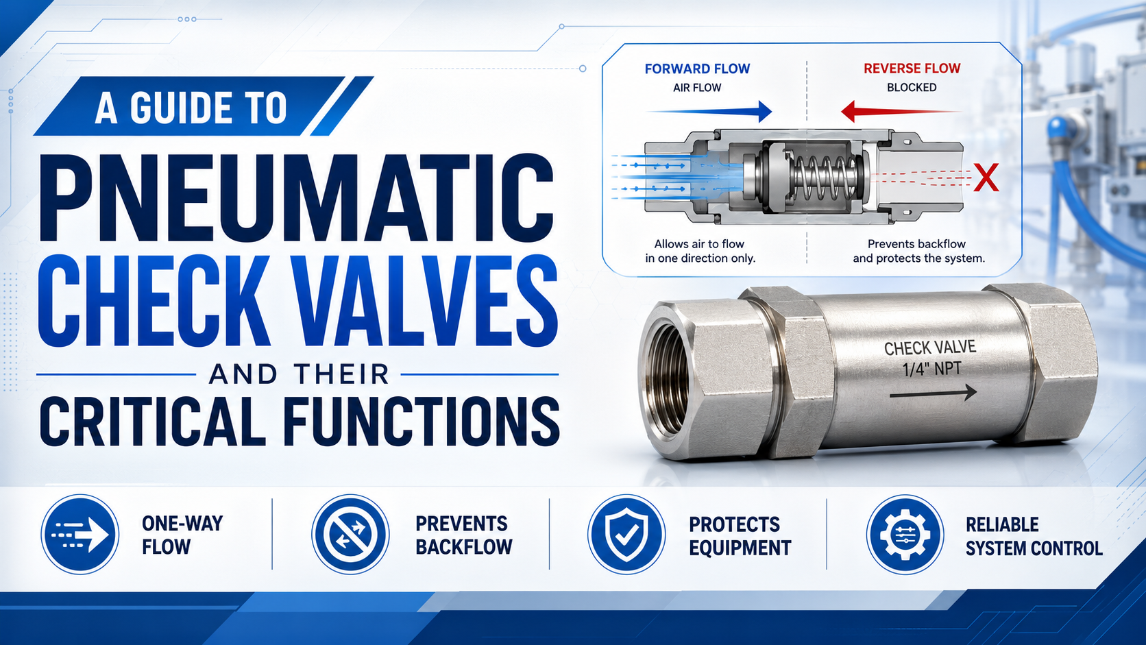
A pneumatic check valve allows air to pass in one direction and restricts reverse flow. That simple function can isolate branches, prevent cross-flow, retain pressure temporarily, protect a regulator from downstream pressure, or provide the free-flow path inside a one-way speed controller.
It cannot guarantee that a suspended load is safe. Real check valves have cracking pressure, forward pressure loss, reverse leakage, contamination limits, and a defined response. Select the valve from those parameters and the circuit’s failure modes, not from port size alone.
Key Takeaways
- Cracking pressure must be below the minimum available forward differential but high enough to resist unwanted opening.
- Forward-flow capacity and reverse-leakage performance are separate specifications.
- A pilot-operated check valve can release trapped pressure on command, but it does not replace a machine risk assessment or mechanical load restraint.
- Test the valve at working flow, minimum supply pressure, worst load, and the required safe state.
What Does a Pneumatic Check Valve Do?
ISO 1219-1 standardizes graphical symbols for fluid-power components, including non-return valves, so a check valve can be identified by function rather than housing shape (ISO 1219-1, 2012). A pneumatic check valve is an automatic non-return valve that opens under an allowed forward pressure differential and seats when flow tries to reverse.
The valve normally contains a seat and a moving element such as a poppet, ball, diaphragm, or cartridge. A spring may push the element toward the seat. Forward inlet pressure must create enough force to overcome the spring, friction, and downstream pressure. Reverse pressure then helps press the element onto the seat.
Three different values describe that behavior:
- Cracking pressure: the forward differential at which the valve begins to open under the manufacturer’s test definition.
- Forward pressure drop: the inlet-to-outlet pressure loss at a stated flow and pressure condition.
- Reverse leakage: the measured flow past the closed element at a stated reverse differential.
These values answer different questions. Low cracking pressure does not prove high flow capacity. A large nominal flow does not prove bubble-tight reverse shutoff. “Zero leakage” should be used only when the data sheet defines the test medium, pressure, duration, temperature, and acceptance limit.
Treat the check valve as two components sharing one body: a forward-flow restriction and a reverse-flow seal. The application must pass both tests independently.
How Do Cracking Pressure and Pressure Drop Affect the Circuit?
ISO 6358-1 defines methods for determining the flow-rate characteristics of pneumatic components using compressible fluids (ISO 6358-1, 2013). In a check-valve circuit, the available forward differential must first overcome cracking pressure, then support the pressure drop created by the required airflow.
Consider a branch with 6 bar upstream pressure and 5.8 bar downstream pressure while the actuator is moving. Only 0.2 bar differential is available across every restriction in that section. A check valve that needs most of that differential to open leaves little margin for tubing, fittings, or the directional valve. Static regulator pressure can therefore look acceptable while the cylinder starves during flow.
The opening process is progressive. At cracking pressure, the moving element has only begun to lift. Full catalog flow usually requires a larger differential. This is why selecting from the cracking-pressure value alone can produce slow filling, delayed pilot response, or an actuator that hesitates at low supply pressure.
Use the worst operating condition:
- Minimum upstream pressure while the machine is flowing.
- Maximum downstream pressure before the valve opens.
- Required instantaneous flow, not only average consumption.
- Tube, fitting, manifold, silencer, and directional-valve losses.
- Temperature and contamination conditions that can change seal friction.
The pneumatic valve pressure-drop calculation guide covers Cv and compressible-flow assumptions in more detail. For a check valve, confirm that the chosen calculation matches the manufacturer’s published rating method.
Check-Valve Types by Pneumatic Function
ISO 4414 covers general rules and safety requirements for pneumatic fluid-power systems and components (ISO 4414, 2010). The useful design split is not simply ball versus poppet; it is whether the circuit needs automatic one-way flow, an adjustable restriction with bypass, or a normally locked path that opens from a pilot signal.
| Valve arrangement | Main function | Best fit | Main limitation |
|---|---|---|---|
| Spring-loaded poppet check | Automatic one-way flow | General branch isolation and pressure separation | Spring adds cracking pressure |
| Ball check | Compact automatic non-return function | Simple inline flow where the specified orientation is acceptable | Seating and orientation depend on design |
| Cartridge or inline check | One-way function in a small envelope | Manifolds, fittings, and point-of-use installation | Small passages can limit flow |
| Pilot-operated check | Lock flow until a pilot signal releases it | Controlled pressure retention and actuator locking circuits | Needs adequate pilot pressure and safe trapped-energy handling |
| One-way flow control | Free flow one way, adjustable restriction the other | Meter-in or meter-out cylinder speed control | It is not a plain check valve |
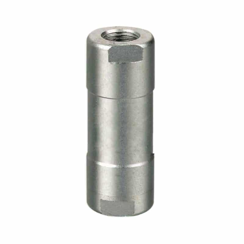
A compact inline check is useful near a cylinder or manifold when space is limited. Installation convenience still does not establish its flow capacity. Read the arrow, port specification, pressure range, compatible tube or thread, seal material, leakage value, and mounting restrictions for the exact model.
Swing checks are common in larger liquid and process piping, but they are rarely the first choice for compact industrial pneumatic circuits. Their operation can depend strongly on orientation, gravity, flow velocity, and disc travel. Use them only when the manufacturer rates the design for the gas service, mounting position, cycling rate, and required response.
For cylinder speed control, use the meter-in versus meter-out guide to distinguish the free-flow check path from the adjustable needle path. Turning the adjustment knob changes the restriction, not the basic reverse-blocking purpose of the check element.
Can a Check Valve Safely Hold a Pneumatic Load?
OSHA’s hazardous-energy rule, 29 CFR 1910.147, requires an energy-control program where unexpected energization, startup, or release of stored energy could injure employees (OSHA Control of Hazardous Energy, accessed 2026). A check valve alone is not an energy-isolation procedure and should not be treated as the sole restraint for a suspended load.
Air is compressible. A trapped cylinder chamber can still move if seals leak, tubing expands, a fitting fails, temperature changes, the load shifts, or the opposite chamber vents. A standard check valve may slow reverse flow without providing a verified holding function. Even a pilot-operated check valve has leakage, pilot-pressure, release, and trapped-energy requirements.
A load-holding design may need several layers:
- A valve arrangement rated for the intended holding function.
- A mechanical rod lock, brake, prop, pin, or blocking device where movement can create a hazard.
- Load-control logic that prevents uncontrolled motion during normal release.
- A monitored safe state after loss of power, pilot pressure, or main supply.
- A defined method to dissipate stored pressure before maintenance.
- A machine-specific risk assessment and applicable safety standard review.
The dangerous moment can be release, not only leakage. If pilot pressure opens a locked valve while the opposing chamber is already exhausted, the load may move before the directional circuit establishes control. Sequence the pilot signal, chamber pressure, exhaust path, and brake release as one function.
“Pressure retained” and “load restrained” are different acceptance tests. Pressure retention measures pneumatic leakage. Load restraint measures machine motion under gravity, external force, seal leakage, component failure, and the defined fault state.
Pilot-Operated Check Valve Selection
A pilot-operated check valve adds a third pressure relationship to the two-port check function: pilot pressure must generate enough opening force against the locked-port pressure and internal spring force. ISO 4414 requires pneumatic systems to address control, component application, and predictable behavior during pressure changes (ISO 4414, 2010).
Do not assume that any available pilot signal will unlock the valve. Obtain the manufacturer’s pilot ratio or release-pressure curve. Then evaluate the highest trapped load pressure, minimum pilot pressure during motion, back pressure at the pilot exhaust, and any area ratio inside the valve.
The RFQ should identify:
- Normal and maximum pressure at the locked port.
- Minimum available pilot pressure at the valve during release.
- Pilot ratio or manufacturer release curve.
- Required main-port flow after opening.
- Internal and external pilot arrangement.
- Reverse leakage acceptance limit.
- Decompression or soft-release requirement.
- Behavior after pilot, electrical power, or supply loss.
Mount the valve close to the actuator when the goal is to minimize the volume between the holding valve and cylinder. Less trapped tube volume can reduce compliance and limit the air released by a downstream hose failure. It does not eliminate movement from cylinder seal leakage or mechanical deflection.
The pilot-operated valve guide explains how a small pilot passage controls a larger main flow. Check-valve selection adds the locked-pressure and release-sequence questions that an ordinary pilot-operated directional valve may not have.
Installation and Commissioning
ISO 4414 applies to the design, construction, modification, installation, and use of pneumatic systems (ISO 4414, 2010). Correct installation starts by matching the valve’s marked flow direction and documented mounting orientation, then keeping contamination and mechanical stress away from the seat.
Follow this installation sequence:
- Isolate and dissipate pneumatic energy using the machine’s approved procedure.
- Confirm the arrow points in the intended free-flow direction.
- Verify the permitted orientation for gravity-sensitive ball or swing designs.
- Clean new tubing and fittings before connecting them.
- Keep thread sealant, tape fragments, chips, and liquid sealant out of the flow path.
- Support rigid piping so valve ports do not carry alignment or bending loads.
- Use the specified thread type, engagement, and tightening method.
- Provide access for pressure measurements, inspection, and replacement.
- Test both forward operation and reverse sealing before production release.
Port markings matter. An arrow usually identifies the allowed flow direction, not the desired cylinder movement. Trace the circuit from supply to actuator and from actuator to exhaust. On a one-way flow controller, the internal check bypass may make the free-flow direction opposite to what an installer expects from the knob location.
Contamination often creates intermittent faults. A particle can hold the seat slightly open and create reverse leakage, then move away during the next cycle. Installing a finer filter is not automatically the cure; the filter, valve, lubricator policy, condensate management, and seal compatibility must follow the component manufacturers’ requirements.
How Do You Test Forward Flow and Reverse Leakage?
ISO 6358-1 separates pneumatic flow characterization from informal port-size comparisons, while ISO 4414 requires verification consistent with the system’s intended function (ISO 6358-1, 2013; ISO 4414, 2010). A useful field test records forward differential under flow and reverse leakage under a controlled pressure boundary.
Forward-flow test
Run the machine at the highest expected coincident demand. Measure pressure immediately upstream and downstream of the check valve with instruments that respond fast enough for the cycle. Record flow, supply pressure, cylinder stroke time, load, valve orientation, and air temperature. A static reading with the actuator stopped cannot reveal the valve’s dynamic pressure loss.
Reverse-leakage test
Isolate the test boundary, apply the approved reverse differential, allow temperature and pressure to stabilize, and measure decay or flow for a defined time. Include the connected tubing, fittings, cylinder seals, and instruments in the boundary description. Otherwise, a falling pressure cannot be assigned to the check valve alone.
Never disconnect a pressurized line merely to see whether air escapes. Use test ports, rated instruments, guarded fixtures, and a controlled depressurization procedure. If the circuit holds a load, secure the load mechanically before changing a valve or opening the pneumatic boundary.
A check-valve test needs two baselines: pressure loss at accepted production flow and reverse leakage at an agreed differential. Replacing a valve because “pressure falls” is guesswork until the test boundary excludes cylinder seals, fittings, tubing, and venting regulators.
What Failure Symptoms Point to the Check Valve?
OSHA requires stored energy to be rendered safe during servicing under the conditions covered by 29 CFR 1910.147 (OSHA Control of Hazardous Energy, accessed 2026). Diagnose a suspected check valve only after the machine and any supported load are in a verified safe state.
| Symptom | Possible check-valve cause | Other causes to exclude | Useful test |
|---|---|---|---|
| Slow forward motion | Undersized passage, high cracking pressure, contamination | Small tube, blocked silencer, low supply, directional-valve restriction | Dynamic upstream/downstream pressure |
| Pressure decays while stopped | Seat damage or contamination | Cylinder seal leakage, fitting leaks, venting regulator | Isolate smaller boundaries and measure decay |
| Valve chatters | Marginal differential, pulsating flow, oversized element | Compressor pulsation, unstable regulator, vibration | Trend pressure on both ports |
| Pilot check will not release | Insufficient pilot force or trapped back pressure | Blocked pilot tube, wrong porting, directional-valve state | Measure pilot and locked-port pressure together |
| Load moves after stop | Reverse leakage or unintended pilot release | Cylinder leakage, hose expansion, mechanical drift | Secure load, then test pneumatic boundaries separately |
Do not jump from symptom to replacement. A new valve can mask a supply-pressure or contamination problem for a short time. Inspect removed parts for particles, seat marks, damaged elastomer, corrosion, lubricant deposits, or thread-seal debris. The failure evidence should change the circuit or maintenance action when appropriate.
Maintenance intervals must come from the component documentation, risk level, cycle count, contamination history, leakage trend, and machine duty. A calendar-only monthly or annual replacement rule is not credible across every pneumatic application. Condition monitoring works better when the machine has a known-good pressure-drop and leakage baseline.
What Information Belongs in a Check-Valve RFQ?
ISO 4414 covers component application as part of pneumatic system safety, and ISO 6358-1 provides a standardized basis for comparing compressible-flow characteristics (ISO 4414, 2010; ISO 6358-1, 2013). A useful RFQ therefore describes function, pressure, flow, leakage, environment, and failure behavior rather than requesting “one check valve” by thread size.
Send these details:
- Circuit function and a marked pneumatic schematic.
- Free-flow direction and required reverse-blocking direction.
- Air or other gas, filtration, lubrication, moisture, and contamination conditions.
- Minimum, normal, and maximum upstream pressure.
- Downstream pressure before opening and maximum reverse differential.
- Required flow and allowable forward pressure drop.
- Maximum acceptable reverse leakage and test condition.
- Required cracking pressure or opening behavior.
- For pilot checks, locked-port pressure, pilot pressure, pilot ratio, and release sequence.
- Port thread, tube size, mounting space, orientation, and connection standard.
- Ambient and medium temperature, vibration, corrosion, and washdown exposure.
- Cycle frequency, expected service life basis, and maintenance access.
- Required state after loss of pilot pressure, electrical power, or main supply.
- Load-holding and personnel-safety requirements, including mechanical restraint.
The RFQ should also state how the valve will be accepted. Examples include maximum pressure drop at a defined flow, maximum reverse leakage at a defined differential, successful release at minimum pilot pressure, and no hazardous movement during the specified fault sequence.
Pneumatic Check Valve FAQ
What is cracking pressure in a pneumatic check valve?
Cracking pressure is the forward inlet-to-outlet differential at which the valve begins to open under the manufacturer’s test definition. It is not the pressure needed for full rated flow. Select it below the minimum available forward differential, then check the pressure drop at the actual required flow.
Does a check valve have zero reverse leakage?
Not unless the manufacturer specifies a zero- or bubble-tight acceptance test for the exact model and conditions. Seat design, particles, seal material, reverse differential, temperature, wear, and test duration affect leakage. Use a stated leakage limit rather than assuming that “closed” means mathematically zero flow.
Can a check valve keep a vertical cylinder from falling?
It may restrict reverse flow, but it should not be the only protection against hazardous load movement. Evaluate cylinder seal leakage, trapped-air compliance, hose failure, pilot release, and component failure. Use rated load-holding hardware, mechanical restraint, safe exhaust sequencing, and a machine risk assessment where required.
Why does a check valve cause excessive pressure drop?
Possible causes include insufficient flow capacity, high cracking pressure, a partly opened element, contamination, incorrect orientation, or a large demand peak. Measure pressure on both sides during the actual motion. Then check the rest of the air path before assigning the entire loss to the valve.
What is the difference between a check valve and a one-way flow control?
A plain check valve permits flow in one direction and restricts reverse flow. A one-way flow control combines a check bypass with an adjustable restriction, allowing free flow one way and metered flow the other. It is commonly used to set cylinder speed through meter-in or meter-out control.
How often should a pneumatic check valve be replaced?
There is no universal replacement interval. Follow the model documentation and base maintenance on cycle count, leakage trend, pressure-drop trend, contamination, duty, environment, and failure risk. Replace or service the valve when it no longer passes the documented forward-flow, reverse-leakage, or functional acceptance test.
A pneumatic check valve is reliable only when its one-way function is defined quantitatively. Specify the opening differential, forward-flow loss, reverse-leakage limit, installation condition, pilot-release behavior, and safe-state requirement. Then test the complete circuit at the lowest supply pressure and highest operating demand.
External technical references and retrieval dates
ISO 1219-1:2012: Graphical symbols and data-processing conventions for fluid-power systems and components. Retrieved 2026-07-11.
ISO 6358-1:2013: Test methods for determining flow-rate characteristics of pneumatic components using compressible fluids. Retrieved 2026-07-11.
ISO 4414:2010: General rules and safety requirements for pneumatic fluid-power systems and components. Retrieved 2026-07-11.
OSHA, Control of Hazardous Energy: Requirements and guidance related to 29 CFR 1910.147 and hazardous-energy control during servicing. Retrieved 2026-07-11.