

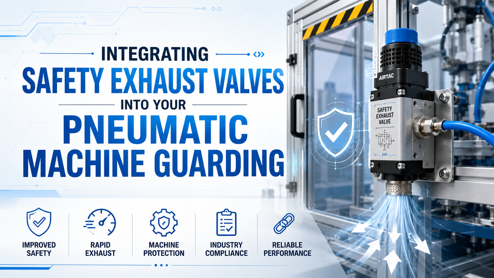
A safety exhaust valve can help a guarded pneumatic machine reach a defined safe state by blocking the air supply and venting downstream pressure when a safety function is demanded. The valve is only one subsystem. Safe integration also depends on risk assessment, control architecture, feedback monitoring, downstream volume, mechanical hazards, reset behavior, and documented validation.
Start with the hazard, not the valve catalog. A machine may need safe exhaust, safe load holding, safe cylinder return, mechanical blocking, or several functions together. Exhausting air is ineffective when gravity, springs, vacuum, trapped pressure, or an accumulator can still move the mechanism.
Safety exhaust is a safety function that removes pneumatic supply and reduces downstream pressure to a validated safe condition. Quick exhaust is a flow function that vents an actuator locally to improve speed. A standard quick exhaust valve is not automatically a safety-rated component and should not be represented as one.
Key Takeaways
- Risk assessment defines the safe state and required PLr.
- A certified valve does not certify the complete machine.
- OSHA sets no universal 0.5-second exhaust limit.
- Safe exhaust does not replace lockout/tagout.
- Vertical loads may need mechanical restraint or safe load holding.
What Makes a Safety Exhaust Valve Different from a Quick Exhaust Valve?
ISO 13849-1:2023 applies to safety-related control-system parts across electrical, hydraulic, pneumatic, and mechanical technologies. It does not prescribe the safety function or PLr for a particular machine (ISO, 2023; retrieved July 11, 2026). That decision begins with the machine risk assessment.
A quick exhaust valve normally sits near a cylinder port and gives exhaust air a shorter route to atmosphere. Its purpose is faster actuator motion. It may have no redundant elements, diagnostic feedback, defined fault response, B10d data, or third-party functional-safety assessment.
A safety exhaust valve usually performs a 3/2 normally closed function: energization supplies air, while de-energization blocks the inlet and connects downstream pressure to exhaust. Depending on the required architecture, the product may use one valve element, redundant valve elements, internal monitoring, or external position or pressure feedback.
The distinction affects purchasing language. Ask for the declared safety function, applicable standard, Category, PL or SIL capability, diagnostic method, B10d or PFHd data, mission time, allowed operating conditions, fault reaction, reset behavior, and integration manual. Do not accept “fail-safe” as a substitute for those records.
Parker’s P33 data provides a useful product-level example. The valve uses an externally monitored redundant dual-poppet design and is described as suitable up to Category 4, PL e and SIL 3 when integrated correctly. Its published switching values and certification apply to that product, not to every valve or every completed machine (Parker, 2024; retrieved July 11, 2026).
For the fluid-power difference, compare this safety function with how a standard quick exhaust valve works. The two components may both vent air, but they solve different engineering problems.
How Does Risk Assessment Define the Required Safety Function?
ISO 12100:2010 defines a machinery risk-assessment and risk-reduction method covering hazard identification, risk estimation, evaluation, protective measures, and documentation (ISO, 2010, confirmed 2022; retrieved July 11, 2026). The exhaust-valve specification should follow that process.
Document the hazardous motion, exposed people, operating modes, foreseeable misuse, severity of harm, exposure frequency, and possibility of avoidance. Then define what the pneumatic system must do when a guard opens, a light curtain is interrupted, an emergency stop is pressed, or a fault is detected.
The resulting safety function needs measurable acceptance criteria. Typical criteria include:
| Safety-function element | Question to answer | Validation evidence |
|---|---|---|
| Trigger | Which guard, sensor, emergency stop, or fault demands the function? | Cause-and-effect matrix and electrical drawings |
| Supply isolation | Must upstream air be blocked, and at what valve location? | Pneumatic schematic and fault test |
| Pressure reduction | Which volume must vent, and what pressure is considered safe? | Pressure trace at the defined test point |
| Mechanical state | May an axis drop, drift, clamp, or coast after pressure loss? | Load and motion test under worst-case conditions |
| Monitoring | How will the controller detect a valve that does not switch or exhaust? | Diagnostic test and controller logic review |
| Reset | What deliberate action is required after a demand or detected fault? | Restart and fault-reset test |
| Performance | What PLr or SIL is required by the risk assessment? | Safety calculation and subsystem documentation |
ISO 13849-1 does not allow the valve label to determine PLr. It provides a methodology for designing and integrating the safety-related parts after the safety function is defined. The complete architecture may include the input device, logic solver, output valve, pneumatic circuit, diagnostic feedback, and mechanical response.
Where Should the Valve Be Installed?
ISO 4414:2010 addresses significant hazards in pneumatic fluid-power systems and applies to system design, construction, modification, installation, operation, maintenance, and cleaning (ISO, 2010, confirmed 2021; retrieved July 11, 2026). Valve placement must therefore be evaluated as part of the complete pneumatic system.
Install the safety exhaust valve so the defined hazardous downstream volume is isolated and vented without unintentionally disabling circuits that must retain pressure. A valve placed at the machine air entry may vent a large volume slowly. A valve placed near one actuator may leave other hazardous branches pressurized.
Review every branch between the safety valve and the hazard:
- Accumulators and air receivers
- Long hoses, manifolds, and large cylinder chambers
- Check valves and pilot-operated check valves
- Regulators and soft-start units
- Flow controls, silencers, and restricted exhaust piping
- Vacuum generators and vacuum reservoirs
- Pressure boosters
- Closed-center directional valves
- Tooling with trapped cavities
Do not route a safety exhaust through an ordinary muffler without checking the approved configuration. A clogged, undersized, or substituted silencer can change pressure-decay performance. Use the manufacturer’s permitted exhaust accessory and include it in testing.
The valve should also be accessible for inspection without encouraging bypass. Protect connectors, tubing, and feedback sensors from impact, contamination, and unauthorized adjustment. The pneumatic diagram, terminal plan, software safety logic, and physical installation must agree.
How Should the Valve Connect to Guards and Safety Controls?
ISO 13850:2015 specifies emergency-stop design principles independent of the energy technology, but it does not define braking, shielding, reversal, or every other function that may form part of the machine response (ISO, 2015; retrieved July 11, 2026). An emergency stop is therefore an input to a defined safety function, not a complete pneumatic design.
The same rule applies to guard switches and light curtains. The sensor detects access or intrusion; the safety logic evaluates the channels; the output stage commands the valve; feedback confirms the expected valve or pressure state; and the machine’s physical response must reach the validated safe condition.
Higher-risk architectures may use two independent output channels and redundant valve elements. Parker’s integration guide notes that achieving the intended Category and Performance Level also depends on plumbing, wiring, pulse testing, and the monitoring design (Parker, retrieved July 11, 2026).
Key integration checks include:
- The safety outputs match the valve coil and diagnostic requirements.
- Short-circuit and cross-fault detection are implemented as required.
- Valve feedback is evaluated within the documented timing window.
- A detected discrepancy prevents the next hazardous cycle.
- Reset is deliberate and cannot initiate hazardous motion.
- Pressure restoration uses the approved soft-start arrangement where required.
- The safety program and pneumatic drawings use the same channel designations.
For ordinary control-valve functions outside the safety subsystem, see the guide to building a reliable pneumatic circuit with modular valves. Keep standard machine control and safety-related control requirements clearly separated in the documentation.
Sizing by Pressure-Decay Performance
Parker publishes 23.3 ms supply switching and 42.7 ms exhaust switching for one P33 configuration, but those component values do not predict the machine’s total pressure-decay or stopping time (Parker, 2024; retrieved July 11, 2026). Downstream volume and restrictions still control the result.
Define the acceptance pressure at the point relevant to the hazard. “Zero pressure” may be impractical as a timing threshold, while a pressure gauge at the valve may not reveal trapped pressure behind a check valve. The risk assessment and mechanical analysis must establish what pressure or motion state is safe.
Collect the variables needed for preliminary selection:
- Maximum and minimum supply pressure
- Total downstream volume, including tubing and manifolds
- Cylinder chamber positions at the worst-case demand
- Valve exhaust flow data over the relevant pressure range
- Exhaust-port fittings and permitted silencer
- Minimum operating temperature
- Contamination class and filtration
- Back pressure at the exhaust
- Required pressure threshold and elapsed time
A simple liquid-flow equation such as (Q = C_vsqrt{Delta P/SG}) is not enough for depressurizing compressed air. Gas flow can become choked, and the pressure changes throughout the event. Use manufacturer exhaust curves or approved sizing software, then confirm the installed machine with a calibrated pressure transducer and time-correlated safety signal.
The article on pneumatic valve Cv sizing is useful for general flow comparison. It does not replace safety validation or a compressible pressure-decay test.
Calculator tools: none. The site’s general Cv and tube-volume calculators are not appropriate as proof of a safety function.
Why Exhausting Air May Not Produce a Safe State
OSHA 1910.147 explicitly includes pneumatic energy and requires potentially hazardous stored or residual energy to be relieved, disconnected, restrained, or otherwise rendered safe after lockout or tagout is applied (OSHA, retrieved July 11, 2026). Pressure reduction alone is not always sufficient.
A vertical cylinder can descend when pressure disappears. A clamp can release a suspended workpiece. A spring-return actuator can move to its de-energized position. Vacuum tooling can drop a load. A mechanically over-center linkage may release stored force even after the gauge reaches zero.
Possible risk-reduction measures include:
- Mechanical blocks, props, rod locks, or load brakes
- Counterbalance or load-holding arrangements with a validated fault response
- Safe cylinder return instead of immediate free exhaust
- Independent restraint for suspended tooling
- Controlled vacuum monitoring and a defined load-release strategy
- Bleed points for isolated cavities
- Pressure sensors at the volume that matters
Do not assume a pilot-operated check valve solves the whole problem. It may hold a load while also trapping hazardous pressure. The safe state, service access method, and recovery procedure must be evaluated together.
Where loss of pressure can release a load, compare the exhaust function with cylinder rod-lock behavior and the design checks for vertical lifting cylinders. Neither device should be credited without application-specific validation.
Machine Guarding Is Not a Substitute for Lockout/Tagout
OSHA 1910.147 requires documented hazardous-energy control procedures for covered servicing and maintenance, including shutdown, isolation, lock application, stored-energy control, and verification (OSHA, retrieved July 11, 2026). A control-system stop or de-energized solenoid is not automatically an energy-isolating device.
Production safeguarding and servicing isolation have different purposes:
| Situation | Typical protection basis | Safety exhaust valve role |
|---|---|---|
| Normal automatic operation | Fixed guards and control system | Normally energized when operation is permitted |
| Guard opening for an authorized production task | Risk-assessed safeguarding and safety function | May block supply and exhaust the defined zone |
| Emergency stop | Emergency-stop function plus machine-specific risk reduction | May contribute to the safe state |
| Maintenance, repair, or clearing with safeguards ineffective | Hazardous-energy control procedure | May assist pressure removal but does not by itself establish LOTO |
| Work under a raised or suspended load | Isolation plus mechanical restraint | Exhaust must not cause uncontrolled descent |
OSHA also requires verification that isolation and de-energization have been accomplished before covered work begins. If pressure can reaccumulate, verification must continue until the work is complete or reaccumulation is no longer possible.
How Should the Safety Function Be Validated?
ISO 13849-2:2012 specifies validation by analysis and testing of the safety functions, achieved Category, and achieved Performance Level for systems designed under ISO 13849-1 (ISO, 2012; retrieved July 11, 2026). Validation must cover the installed circuit, not only a component data sheet.
Create a test plan from the safety requirements specification. Test normal demands and credible faults, including:
- Each guard, emergency stop, and protective device channel
- Loss of electrical power and loss of pneumatic supply
- One output channel failing to switch
- Valve feedback stuck on or off
- Blocked or restricted exhaust where reasonably foreseeable
- Minimum and maximum supply pressure
- Worst-case downstream volume and cylinder position
- Cold-start and warm operating conditions
- Loss and restoration of communication to the safety controller
- Reset after demand and reset after detected fault
- Pressure reaccumulation and unexpected restart
Record the safety input transition, controller output, valve feedback, downstream pressure, and hazardous motion on the same time base. The acceptance result should identify the test point, sensor accuracy, threshold, machine configuration, load, supply pressure, and environmental conditions.
Do not invent a daily, monthly, or annual test interval for every valve. Use the manufacturer instructions, machine risk assessment, applicable type-C standard, use frequency, contamination conditions, and previous test results to establish inspection and proof-test intervals.
Validation also needs configuration control. Record the valve model and revision, safety-controller program checksum, wiring drawing, pneumatic schematic, parameter values, pressure sensor, silencer, tubing sizes, test equipment, results, and approver. A replacement valve or modified exhaust path may require revalidation.
Integration Checklist
ISO 13849-1:2023 applies to high-demand and continuous-mode safety-related control systems and their subsystems, regardless of technology (ISO, 2023; retrieved July 11, 2026). Use this checklist to organize the work, then have the responsible machinery-safety professional approve the design and validation.
- Risk assessment identifies the pneumatic hazards and foreseeable access tasks.
- Safety requirements define the safe state, trigger, PLr or SIL, pressure threshold, motion limit, and reset behavior.
- The selected valve declares the required safety function and provides current integration data.
- Ordinary quick exhaust valves are not credited as safety-rated subsystems.
- Supply isolation and exhaust cover every hazardous downstream branch.
- Trapped cavities, check valves, accumulators, boosters, and vacuum reservoirs are addressed.
- Gravity, spring, clamp, and suspended-load behavior is controlled.
- Electrical outputs, feedback, pulse tests, and discrepancy timing match the integration guide.
- Restart requires the intended deliberate action and does not initiate hazardous movement.
- Installed pressure-decay and stopping behavior are tested under worst-case conditions.
- Credible faults are injected and the reaction is recorded.
- Servicing procedures distinguish safeguarding from OSHA LOTO obligations.
- Drawings, calculations, software revisions, test records, and replacement requirements are controlled.
Frequently Asked Questions
Can a standard quick exhaust valve be used as a safety exhaust valve?
Not merely because it vents air quickly. A safety-related application needs a defined safety function, architecture, reliability data, diagnostics, fault response, and validation appropriate to the required PLr or SIL. Use a product with documented safety suitability and integrate it according to its certified configuration.
How fast must a safety exhaust valve depressurize a machine?
There is no universal 0.5-second OSHA limit for all pneumatic machines. The risk assessment must define the safe pressure or motion state, and validation must measure the total response from safety input through pressure decay and mechanical stopping under the worst credible operating condition.
Does a safety exhaust valve replace lockout/tagout?
No. It can support pressure removal, but OSHA 1910.147 requires covered servicing work to use an energy-control procedure with isolation, lockout or tagout, stored-energy control, and verification. A solenoid command or safety-controller output is not automatically a lockable energy-isolating device.
Does every high-risk machine need a Category 4, PL e valve?
No. ISO 13849-1 states that it does not specify the safety functions or PLr for particular applications. The machine risk assessment and applicable type-C standard determine the required risk reduction. The achieved PL then depends on the complete input, logic, output, diagnostics, and integration.
Why can a cylinder still move after the air supply is exhausted?
Gravity, springs, external loads, trapped pressure, vacuum, accumulators, and mechanical stored energy can continue moving the mechanism. The design may need a rod lock, mechanical prop, load-holding arrangement, safe return, or another independent measure in addition to exhaust.
Conclusion
Integrating a safety exhaust valve into pneumatic machine guarding is a functional-safety design task, not a valve substitution. Define the hazard and safe state first. Then select the architecture, locate the valve, manage trapped and mechanical energy, monitor the safety function, and validate the installed machine.
A safety-rated component can contribute documented reliability, but it cannot certify the surrounding circuit. The machine designer or integrator remains responsible for the risk assessment, safety requirements, achieved PL or SIL, pressure-decay test, fault testing, restart behavior, and the boundary between production safeguarding and hazardous-energy isolation.
Sources
- International Organization for Standardization. ISO 12100:2010, Safety of machinery, risk assessment and risk reduction. Confirmed 2022. Retrieved July 11, 2026.
- International Organization for Standardization. ISO 13849-1:2023, Safety-related parts of control systems. Retrieved July 11, 2026.
- International Organization for Standardization. ISO 13849-2:2012, Validation. Retrieved July 11, 2026.
- International Organization for Standardization. ISO 13850:2015, Emergency stop function. Retrieved July 11, 2026.
- International Organization for Standardization. ISO 4414:2010, Pneumatic fluid power safety requirements. Confirmed 2021. Retrieved July 11, 2026.
- Occupational Safety and Health Administration. 29 CFR 1910.147, The control of hazardous energy. Retrieved July 11, 2026.
- Occupational Safety and Health Administration. 29 CFR 1910.212, General requirements for all machines. Retrieved July 11, 2026.
- Parker Hannifin. P33 Safety Exhaust Valve Integration Guide. Retrieved July 11, 2026.
- Parker Hannifin. P33 Safety Exhaust Valve technical catalogue. November 2024. Retrieved July 11, 2026.