


A reliable modular pneumatic circuit is built by defining the machine states first, then selecting the manifold, valves, pressure zones, exhaust paths, electrical interface, and isolation method as one system. The valve island is only reliable when every station receives enough air, reaches a known fault state, and can be tested without guesswork.
That shifts the design question. Don’t ask only, “Which valve fits this base?” Ask what every actuator must do during run, pause, power loss, air loss, maintenance, and restart. Then prove the answer with dynamic pressure readings and a documented acceptance sequence.
Key Takeaways
- Start with actuator states and simultaneous demand, not an empty manifold drawing.
- ISO 15407 defines 18 mm and 26 mm mounting interfaces, but it doesn’t guarantee functional interchangeability.
- CAGI’s 10% system pressure-drop limit is a ceiling; measure the valve inlet while the machine cycles.
Modular pneumatic circuit is a control assembly built from repeatable valve, manifold, pressure, exhaust, I/O, and isolation modules around a documented machine function.
Valve island is a group of directional valves sharing a base, supply or exhaust galleries, and often a common electrical or fieldbus connection.
Fault state is the defined position or pressure condition that the circuit enters after loss of a command, electrical power, pilot pressure, or main air supply.
[UNIQUE INSIGHT]
Focus the design on an operating state, not one valve station. That state can cross several stations at once. Even a manifold that passes every single-axis bench test can fail when two cylinders extend together, an exhaust gallery sees combined flow, or one pressure zone backfeeds another.
The Reliable Modular Pneumatic Circuit Boundary
ISO 4414:2010 covers pneumatic-system design, construction, modification, assembly, installation, adjustment, continuous operation, maintenance, reliability, energy efficiency, and environmental considerations. That broad scope makes the correct circuit boundary larger than a valve island: it includes the air treatment, isolator, manifold, tubes, actuators, sensors, controls, and stored-energy path (ISO 4414, 2010).
Draw the boundary before selecting part numbers.
Start at the machine’s local air inlet, not the compressor room. End at the actuator ports and position feedback. Include every component that can change pressure, flow, exhaust capacity, motion, or restart behavior.
Use a state table before a pneumatic schematic:
| Machine state | Electrical command | Pneumatic condition | Required actuator behavior | Evidence at acceptance |
|---|---|---|---|---|
| Normal run | PLC outputs active | regulated supply available | commanded axes complete their strokes | cycle time, end sensors, dynamic pressure |
| Pause | commands removed or held | supply may remain | each axis reaches the documented pause state | position and pressure remain predictable |
| Power loss | outputs de-energized | air may remain stored | valves move to their de-energized states | observe actual spool and actuator response |
| Air loss | controls may remain active | pressure decays | loads do not create an uncontrolled motion | decay test and mechanical-risk review |
| Maintenance | control and air isolated | stored air relieved | no unexpected movement is possible | isolation verification before work |
| Restart | supply and power restored | pressure rebuilds | no uncommanded cycle begins | controlled restart test |
Which Valve Modules Belong on the Manifold?
ISO 15407-1 defines mounting interfaces for five-port directional valves in 2 nominal widths, 18 mm and 26 mm, for rated pressure up to 1.6 MPa. It specifies interface dimensions, tolerances, port identification, and actuation-result identification, but explicitly excludes functional characteristics (ISO 15407-1, 2000).
That exclusion is easy to miss.
A mounting standard can establish where ports and fasteners belong without proving that two valves share the same flow, pilot arrangement, center condition, seal material, response time, electrical pinout, or permitted pressure zones. “Fits the footprint” isn’t the same as “works in the circuit.”
Choose each station from its function record:
| Selection field | What to document | Why it matters |
|---|---|---|
| Actuator and motion | single or double acting, stroke, load direction, target time | establishes valve function and flow demand |
| Normal valve state | monostable, bistable, 5/2 or specific 5/3 center | determines pause, power-loss, and restart behavior |
| Pilot arrangement | internal, external, or separate pilot exhaust | affects low-pressure operation and zoning |
| Flow data | ISO 6358 conductance data, Cv, or catalog flow at stated conditions | prevents selection by thread size alone |
| Electrical interface | voltage, wattage, connector, polarity, suppression, fieldbus node | protects PLC outputs and diagnostic behavior |
| Environmental rating | temperature, ingress protection, vibration, washdown exposure | applies to the assembled valve and connector |
| Service method | manual override, station shutoff, module replacement sequence | defines how a fault is isolated safely |
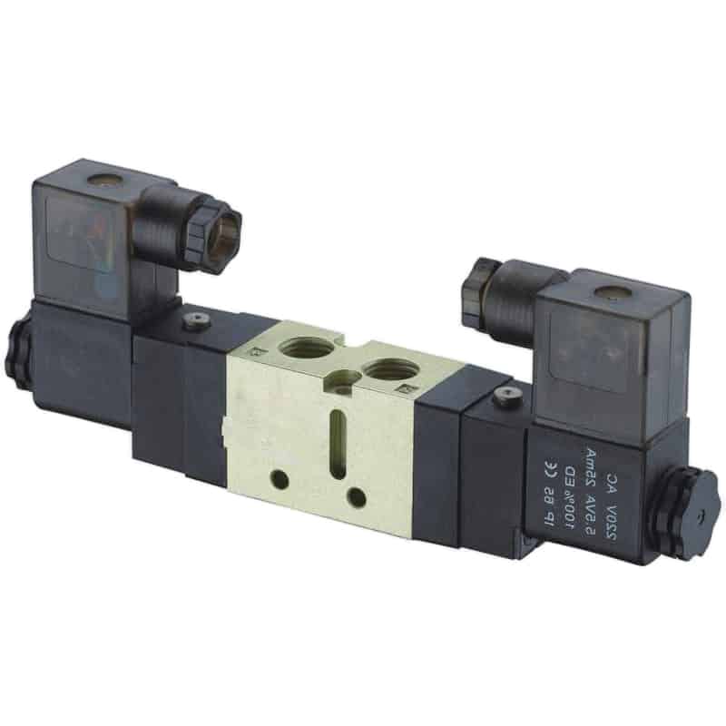
For the underlying port and position logic, use the guide to 4-way directional valve control systems. If the station uses a two-stage main spool, the separate explanation of pneumatic pilot-operated valves covers internal and external pilot behavior.
[UNIQUE INSIGHT]
Base the spare-parts policy on the released function record, not on visual similarity. Two valves can share a footprint and connector while producing different center states or pilot behavior. Store the approved substitute with its tested configuration, not merely a vendor cross-reference.
How Should Shared Supply and Exhaust Be Sized?
ISO 6358-3:2014 provides a method for estimating the overall steady-state flow characteristics of components and piping assembled as a system, including subsonic and choked flow. CAGI adds a plant-level boundary: a well-designed compressed-air system should keep total pressure drop from compressor discharge to point of use within 10% (ISO 6358-3, 2014; CAGI, 2022).
Size the manifold for the worst credible group of simultaneous movements. Adding every station’s peak flow is usually too conservative when the sequence prevents overlap. Sizing from one station is too optimistic when clamps, transfers, ejectors, and blow-off functions can overlap. The control sequence is therefore a pneumatic sizing input.
Use this order:
- Record bore, rod diameter, stroke, working pressure, and target time for every actuator direction.
- Mark which movements can overlap, including maintenance jogs and restart sequences.
- Calculate the required flow for each active group.
- Check the common supply gallery, auxiliary inlet modules, valve paths, fittings, tube ID, and regulator together.
- Check exhaust galleries, silencers, and meter-out controls separately from supply.
- Measure valve-inlet pressure during the worst active group after assembly.
For example, a six-station island may have only three stations in its worst demand group because the PLC sequence prevents the others from moving together. Size from those three real paths, but also test maintenance jog and restart logic. Those modes can create combinations that normal automatic operation never requests.
One gauge at the regulator is not enough.
Add a measurement port at or immediately before the valve island. For long actuator tubes, a second pressure point near the most demanding station helps separate a shared-gallery restriction from a downstream tube or fitting restriction. The existing pressure-drop troubleshooting guide explains that dynamic measurement method in more detail.
Don’t ignore exhaust.
A shared exhaust gallery can create back pressure between stations, especially when several large chambers vent together. If removing a muffler changes cycle time, the valve may be healthy while the exhaust accessory is undersized. The choice between meter-in and meter-out control also changes where restriction belongs.
How Do Pressure and Electrical Zones Change the Layout?
ISO 15407-2 covers the same 18 mm and 26 mm five-port valve sizes while adding an optional electrical connector interface, again up to 1.6 MPa. Parker’s pneumatic valve catalog separately lists valve-island families with multiple-pressure options and flow ranges, showing why mounting, pressure zoning, and electrical architecture must be specified as different layers (ISO 15407-2, 2003; Parker, 2021).
Pressure zoning is useful when clamps, motion axes, grippers, and blow-off functions need different pressures or isolation behavior. It is risky when a zone seal, separator, or external pilot path is assumed rather than documented. Mark every supply zone and every exhaust zone on the manifold drawing. Then mark which pilot air source each valve uses. For example, a low-pressure gripper zone can share the valve island with a higher-pressure transfer axis only when the separator, auxiliary inlet, regulator, and pilot source support that arrangement. If the gripper valve takes an internal pilot from the reduced-pressure zone, lowering grip pressure may also reduce its shifting margin. Electrical zoning deserves the same care. A fieldbus coupler can reduce point-to-point wiring, but it also creates a shared power and communication boundary. Separate these questions:
- Communication power source?
- Which separate power supply feeds the valve coils, which protective device serves it, and what does the risk assessment require during an emergency stop?
- What happens to each station when either supply disappears during a commanded movement?
- Are outputs sourcing or sinking, and does polarity matter?
- Where are surge suppression and protective earth handled?
- Can a failed node interrupt healthy downstream stations or prevent useful diagnostics?
- How is the configured station order matched to PLC addresses?
Air quality is another shared boundary.
ISO 8573-1:2010 classifies compressed-air purity by particles, water, and oil. Specify the required class and measurement location, then verify it before the manifold rather than assuming the compressor-room reading represents the machine inlet (ISO 8573-1, 2010). The related ISO air-quality guide shows how to write that requirement.
What Must the Fault and Safety State Do?
OSHA 29 CFR 1910.147 explicitly includes pneumatic energy and requires machines to be isolated and rendered inoperative before covered servicing where unexpected startup or stored-energy release could injure employees. It also states that push buttons and selector switches are not energy-isolating devices (OSHA 1910.147, retrieved 2026-07-11).
De-energized valve state is part of normal control design, not a complete energy-control procedure. Closed-center spools can trap pressure. Exhaust-center spools can release a vertical load. Bistable valves can remain in their last state after electrical power disappears. Machine risk assessment must decide what is acceptable.
Document at least these four loss conditions separately:
| Loss condition | Question to answer | Test evidence |
|---|---|---|
| PLC command loss | Does the coil de-energize, hold, or receive a fallback command? | force output off and observe valve state |
| Electrical power loss | What state do monostable and bistable valves retain? | remove control and valve power as designed |
| Main air loss | Can gravity, springs, or external loads move an actuator? | isolate supply and record pressure decay and motion |
| Pilot-air loss | Can the main spool still shift or return? | remove the documented pilot source under controlled conditions |
Provide a lockable air-isolation device where the machine’s energy-control design requires it. Relieve or restrain stored energy, account for reaccumulation, and verify isolation before work. If trapped air is intentionally retained for load holding, that decision needs an engineered restraint and a written servicing method, not an assumption that the center valve position is enough.
[UNIQUE INSIGHT]
Design for diagnostic isolation without confusing it with safety isolation. A station shutoff can help find a leaking branch, but a maintenance isolation point must meet the site’s hazardous-energy procedure. Giving both devices the same label or symbol invites the wrong one to be trusted.
A Commissioning Sequence That Finds Weak Links
ISO 4414:2010 applies not only to design but also to installation, adjustment, uninterrupted operation, maintenance, reliable use, and energy efficiency. A commissioning sequence should therefore test the released circuit across several states, not stop after every cylinder moves once (ISO 4414, 2010).
Start with low-risk static checks. Confirm valve order, port labels, tube destinations, connector addresses, regulator settings, manual-override positions, and the documented de-energized state. Check that unused ports are handled exactly as the manufacturer specifies. An exhaust port isn’t a spare connection. Then energize in a controlled sequence. Watch one station at a time before enabling combined motion. Record the inlet pressure at rest and during motion. Compare extend and retract times, check exhaust noise, and confirm each end sensor changes state within the permitted window.
Finally, test the interactions that a single-station check misses:
Use the results as acceptance data, not as a story about how well the circuit “felt.” Record measurement location, gauge or sensor ID, supply setting, active stations, dynamic minimum pressure, stroke times, alarm state, and pass limit. If a limit changes during commissioning, revise the design record and repeat the affected tests.
What Should Go in the Modular Pneumatic Circuit Worksheet?
ISO 6358-3 evaluates a pneumatic assembly from known component and piping flow characteristics, while ISO 15407 separates interface geometry from functional performance. A useful worksheet follows the same logic: it records both compatibility and behavior instead of reducing the design to a manifold part number (ISO 6358-3, 2014; ISO 15407-1, 2000).
Use one row per valve station and separate rows for shared modules. The finished worksheet should be short enough to review but specific enough to reproduce the released configuration.
| Worksheet group | Required fields |
|---|---|
| Circuit identity | machine, circuit name, drawing revision, owner, acceptance date |
| Shared supply | inlet size, isolator, filter/regulator, set pressure, measured dynamic minimum |
| Manifold | series, station count, supply zones, exhaust zones, auxiliary inlets, end-plate orientation |
| Valve station | station number, valve function, normal state, pilot source, flow data, coil and connector |
| Actuator path | actuator, bore, stroke, load direction, tube ID and length, flow-control method |
| Control mapping | PLC address, output type, fieldbus node, sensor inputs, alarm behavior |
| Safety and faults | power-loss state, air-loss state, trapped-energy control, isolation method |
| Acceptance | active demand group, pressure result, stroke time, sensor result, pass limit |
| Spare strategy | approved replacement, required adapter, programmed configuration, retest scope |
[UNIQUE INSIGHT]
Treat the worksheet as the replacement boundary. If a proposed spare changes the valve function, pilot arrangement, flow data, connector, zone seal, or fault state, it is not a like-for-like replacement. The substitution becomes an engineering change that needs the affected acceptance tests repeated.
FAQs About Modular Pneumatic Circuits
The 5 answers below apply the same system boundary used by ISO 4414 and the 10% total pressure-drop ceiling published by CAGI. They address the decisions most likely to be hidden by a compact valve-island drawing: interchangeability, simultaneous demand, zoning, safety isolation, and acceptance evidence (ISO 4414, 2010; CAGI, 2022).
Does an ISO mounting interface make valves interchangeable?
No. ISO 15407-1 defines dimensions, tolerances, port identification, and actuation-result identification for 18 mm and 26 mm interfaces, but it excludes functional characteristics. Confirm valve function, flow data, pilot method, center state, pressure range, seals, connector pinout, power, and zoning before approving a replacement.
Should every valve flow rating be added when sizing the manifold?
Not automatically. Group the stations that can move at the same time, then size the shared supply and exhaust for the worst credible group. Include restart sequences, maintenance jogs, ejectors, and blow-off functions. Finally, measure dynamic pressure at the valve island while that group runs.
When does a modular circuit need more than one pressure zone?
Use separate pressure zones when functions need materially different force, pressure, pilot supply, or isolation behavior. Typical examples include low-pressure grippers beside higher-pressure motion axes. Document zone separators, auxiliary inlets, pilot sources, and exhaust paths so a change at one station cannot silently affect another zone.
Is a valve-island shutoff enough for maintenance lockout?
Only if the site’s energy-control assessment and procedure establish it as the correct energy-isolating device. OSHA 1910.147 requires covered hazardous energy to be isolated and stored or residual energy to be made safe. A control button, PLC command, or diagnostic station shutoff isn’t automatically an energy-isolating device.
What proves that the completed modular pneumatic circuit is reliable?
Reliability is supported by repeatable evidence: correct station mapping, acceptable leakage, stable dynamic inlet pressure, required stroke times, confirmed sensor transitions, documented loss-of-command states, verified isolation, and controlled restart. Record the configuration and limits so replacement or modification work can repeat the affected tests instead of relying on memory.
Source retrieval notes
ISO 4414:2010, Pneumatic fluid power - General rules and safety requirements for systems and their components. Retrieved 2026-07-11.
ISO 15407-1:2000, Five-port directional control valves, sizes 18 mm and 26 mm - Part 1. Retrieved 2026-07-11.
ISO 15407-2:2003, Five-port directional control valves, sizes 18 mm and 26 mm - Part 2. Retrieved 2026-07-11.
ISO 6358-3:2014, Method for calculating steady-state flow-rate characteristics of systems. Retrieved 2026-07-11.
ISO 8573-1:2010, Contaminants and purity classes. Retrieved 2026-07-11.
OSHA 29 CFR 1910.147, The control of hazardous energy. Retrieved 2026-07-11.
Compressed Air and Gas Institute, Technical Brief on Pressure Drop. Retrieved 2026-07-11.
Parker Hannifin, Pneumatic Valve Products, Subbase and Manifold Valves. Retrieved 2026-07-11.
Publisher information: About us | Contact | Privacy policy