

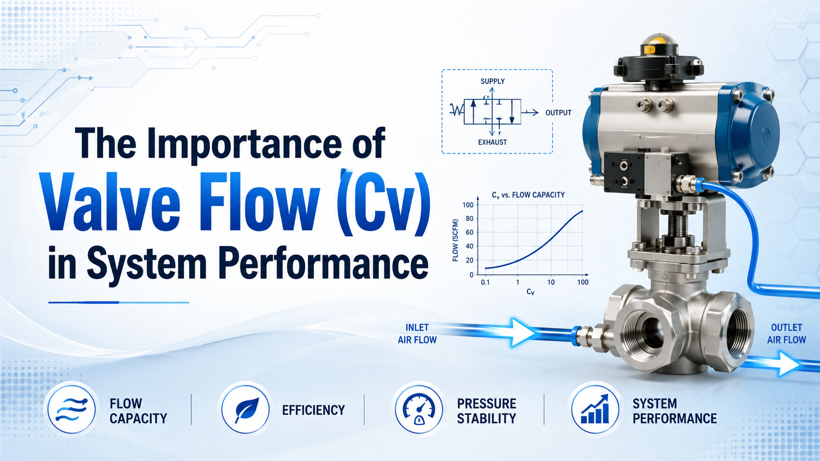
Valve flow coefficient (Cv) matters when a valve restricts the air needed to complete a motion on time. But a slow cylinder does not prove the valve is undersized. Calculate the actuator demand, inspect both supply and exhaust paths, and measure pressure while the cylinder moves before changing the valve.
This guide focuses on that installed-system diagnosis. For Cv definitions, Cv-to-Kv conversion, and rating comparisons, begin with our complete pneumatic valve Cv sizing guide.
Key Takeaways
- Port size does not establish valve capacity; compare Cv or pneumatic flow data for the actual path.
- Parker calculates Cv 1.06 for a 3.25-inch-bore cylinder completing a 12-inch stroke in 1 second at 80 psi.
- Confirm the bottleneck with dynamic pressure readings instead of replacing parts by trial and error.
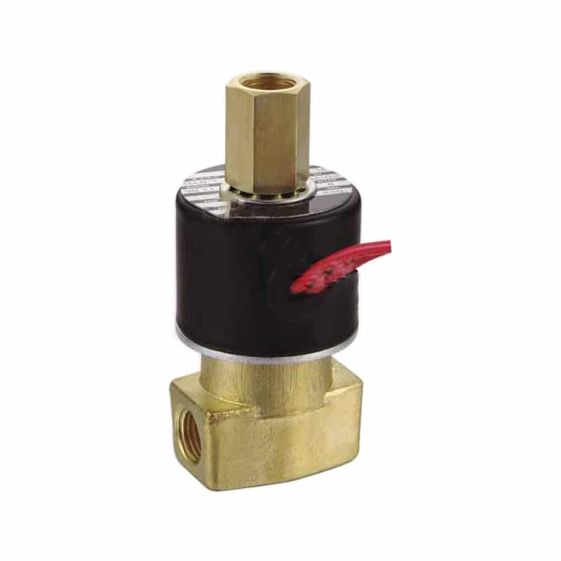
The valve shown above is one example of a directional control component whose port thread, internal path, and published flow capacity all need to be checked. See the XC22/23 Series general-purpose solenoid valve for product details.
Why Can the Right Port Size Still Miss the Target Cycle Time?
A valve can have the specified thread and still produce excessive pressure loss during motion. The port is only the connection interface. Spool passages, internal turns, manifold galleries, fittings, tubing, speed controllers, and exhaust silencers determine the capacity of the complete installed route.
Cv is therefore a comparison value, not a diagnosis by itself. Two 1/4-inch valves can have different Cv values, and the inlet-to-work-port path may differ from the work-port-to-exhaust path. A cylinder that extends correctly but retracts slowly may have an exhaust restriction rather than an undersized supply path.
Use these observations to narrow the fault:
| Symptom | First measurements | Likely areas to inspect |
|---|---|---|
| Both directions are slow | valve-inlet pressure during motion | FRL, shared manifold supply, inlet fitting |
| One direction is slow | pressure at both cylinder ports | one valve path, speed controller, muffler |
| First cycle passes, repeated cycles slow | minimum dynamic supply pressure | compressor capacity, receiver, branch pipe |
| Motion starts fast and finishes hard | stroke-time trace and cushioning | valve capacity, meter-out setting, cushion |
| One machine state fails only | command and pressure timestamps | overlapping actuator demand, control delay |
How Much Flow Does the Actuator Need at the Target Stroke Time?
Start with bore, stroke, working pressure, and permitted stroke time. Parker’s published pneumatic example uses a 3.25-inch bore, 8.30-square-inch piston area, 12-inch stroke, 1-second travel time, 80 psi supply, a 6.4 compression factor, and a 0.048 constant to obtain Cv 1.06 (Parker Engineering Data).
That example is valuable because it begins with required motion rather than port size. Use the manufacturer’s pneumatic sizing method for the candidate valve and keep its units and stated test conditions intact. Do not calculate chamber volume in cubic feet per minute and label it SCFM without converting the compressed volume to the declared standard conditions.
Record the two directions separately. The rod reduces retract-side effective area on a conventional double-acting cylinder, while tubing length and exhaust hardware may also differ. For a rodless cylinder, use its manufacturer’s chamber data when available instead of assuming that a fixed percentage should be added to Cv.
How Should Cv Be Used for Compressed Air?
Cv’s familiar definition is based on water: US gallons per minute at 60°F through a fully open valve with a 1 psi pressure drop (ISA, Process Control Basics, Chapter 5). That makes Cv useful for capacity comparison, but its basic liquid equation is not a complete compressed-air sizing equation.
For liquid service, the relationship is:
Q = Cv × sqrt(DeltaP / SG)
where Q is US gpm, DeltaP is psi, and SG is specific gravity relative to water. Air sizing must additionally account for absolute upstream pressure, downstream pressure, temperature, compressibility, and possible choked flow.
ISO 6358-1 specifies steady-state tests for the flow-rate characteristics of pneumatic components using compressible fluids (ISO 6358-1:2013). When a datasheet provides sonic conductance, critical pressure ratio, or airflow at clearly stated inlet and outlet conditions, use that pneumatic data rather than inventing a universal Cv conversion.
Check the catalog entry for all of the following:
- whether the rating applies to a single flow path or the whole valve;
- inlet and downstream pressure used for a quoted SCFM, NL/min, or L/min value;
- reference temperature and pressure for “standard” flow;
- supply and exhaust ratings for each spool state;
- manifold derating or simultaneous-operation limits.
NIST notes that standard gas-flow units must declare their reference conditions; it also gives 1 cfm = 28.31685 L/min for unit conversion (NIST pressure and gas-flow conversions). A flow number without its reference conditions is incomplete procurement data.
Which Restrictions Matter Beyond the Valve Cv?
The valve is one pressure-loss element in a series circuit. CAGI describes a well-designed compressed-air system as having no more than 10% pressure drop from compressor discharge to point of use and identifies piping, fittings, filters, dryers, separators, and hoses as restriction sources (CAGI Pressure Drop Technical Brief).
That 10% figure is a system-level benchmark, not permission to consume 10% across the directional valve. Allocate an acceptable dynamic pressure loss to each section based on the actuator force and timing requirement.
How Do You Test Whether Cv Is the Actual Bottleneck?
Test one repeatable machine event and synchronize the electrical command, end-position signal, and dynamic pressures. The goal is to locate where pressure is lost during the failing part of the stroke, not merely to confirm that static supply pressure looks normal before motion starts.
- Freeze the test condition. Use the same load, supply setting, speed-controller position, payload, and cycle sequence.
- Timestamp the command and sensors. Separate PLC delay, valve shift time, air-filling time, and mechanical travel.
- Measure P1 at the valve inlet. A large dip here points upstream of the measured valve path.
- Measure P2 near the cylinder port. Compare P1 and P2 during peak flow, not after the piston stops.
- Check exhaust back pressure. Repeat for the opposite direction and temporarily test a known-clean muffler where site safety permits.
- Change one restriction. Substitute a verified higher-capacity valve or shorten one tube run without changing the rest of the circuit.
- Repeat enough cycles to see variation. Report median and worst stroke time, minimum P1, and peak P1-to-P2 differential.
A higher-Cv substitute that improves stroke time while upstream pressure remains stable is strong evidence that the original valve path was limiting. If P1 collapses with both valves, increasing valve Cv will not repair the upstream supply problem.
What Does an Oversized Valve Change?
An oversized on/off directional valve can increase initial acceleration, make cushioning harder to tune, raise exhaust noise, and occupy more manifold or panel space. It does not automatically increase the air required to fill the same cylinder chambers to the same final pressures for each completed cycle. Air consumption and transient flow rate are related but different quantities.
Do not transfer every warning about oversized modulating process-control valves directly to a pneumatic directional valve. A process control valve may suffer poor control authority when it operates near closed; a directional valve normally switches between defined states. For the pneumatic circuit, verify the actual concerns: impact, controllability, exhaust noise, minimum stable speed, cost, and space.
Keep the smallest valve that passes the acceptance test with reasonable margin across minimum supply pressure and maximum expected load. Avoid fixed multipliers such as “always add 25% Cv” unless the machine specification or component manufacturer defines the conditions behind that margin.
Valve Flow Acceptance Worksheet
Use one worksheet per critical motion. It turns “the cylinder seems slow” into comparable procurement and commissioning data.
| Field | Record |
|---|---|
| Actuator | type, bore/effective area, stroke, rod size if applicable |
| Motion requirement | extend and retract target time, allowable variation |
| Load condition | force, mass, orientation, friction, cushion setting |
| Air conditions | minimum dynamic supply pressure, ambient temperature |
| Valve data | model, spool function, Cv or ISO 6358 data for each path |
| Installed route | tube ID/length, fittings, manifold, speed control, muffler |
| Measured result | command-to-motion delay, stroke time, P1 minimum, P2 trace |
| Acceptance rule | pass/fail limit at worst expected operating condition |
For replacement work, send this sheet with the old valve datasheet and photos of the manifold interface. Matching voltage, port thread, and spool function remains mandatory even when the proposed valve has adequate flow capacity.
Frequently Asked Questions
Does a higher Cv always make a pneumatic cylinder faster?
No. Higher valve capacity helps only when that valve path is the meaningful restriction. Cylinder load, upstream pressure, tubing, fittings, meter-out control, cushions, and exhaust hardware can set the speed instead.
Can I select a valve by matching the port size?
No. Match pressure rating, spool function, voltage, interface, and flow data. Identical port threads can connect to different internal passage areas and therefore different flow capacities.
Is the liquid Cv equation valid for compressed air?
Not as a complete gas-sizing method. Use pneumatic manufacturer equations or ISO 6358 data that include upstream and downstream pressure conditions, temperature, and compressible-flow behavior.
Where should pressure be measured during a Cv test?
Measure near the valve inlet and near the active cylinder port, then inspect exhaust back pressure. Use sensors fast enough to capture the pressure dip during the stroke rather than relying only on static gauges.
Should I add a fixed safety factor to calculated Cv?
Use a margin tied to minimum supply pressure, load variation, measurement uncertainty, and future operating range. A universal multiplier is not defensible without stated conditions and manufacturer guidance.