

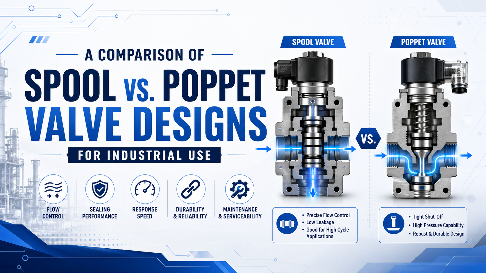
Spool and poppet describe the valve element that opens, closes, or redirects the flow path. A spool slides axially so its lands and grooves connect different ports. A poppet moves onto or away from a seat. Neither architecture is universally faster, cleaner, higher pressure, or easier to maintain. Those results depend on the exact seal, balance, operator, porting, and product rating.
The practical choice is usually straightforward. Start with the circuit function, permitted internal leakage, normal and reverse flow, pressure range, vacuum requirement, response target, media quality, and expected cycle rate. Then compare actual datasheets under the same test conditions.
Key Takeaways
- Spool versus poppet identifies the internal valve element, not whether the valve is direct acting or pilot operated.
- Parker recommends considering a poppet when leakage below 5 drops per minute is required for one two-way cartridge application.
- Use measured flow data, permitted flow direction, crossover behavior, and rated switching time instead of category-wide assumptions.
- Filtration and seal compatibility still matter for both designs.
What is the core difference between a spool valve and a poppet valve?
Festo identifies poppet and piston-spool valves as the two most commonly used compressed-air valve technologies, while noting several subtypes within each family (Festo, 2018). A spool selects flow paths by sliding through a bore; a poppet opens or closes one or more seats with axial sealing contact.
A spool valve is a directional or shutoff valve that uses a cylindrical element with lands, grooves, and sealing regions. Moving the spool changes which body passages communicate. This geometry is well suited to compact 3/2, 5/2, and 5/3 functions because one moving element can switch several ports.
A poppet valve is a valve that places a disc, cone, plug, or shaped elastomer against a seat. Lifting the element creates an annular flow opening; returning it to the seat closes the path. Multiport poppet valves can use several seats and sealing elements, so “poppet” doesn’t mean two ports only.
Here is the first trap: spool/poppet and direct/pilot are different classifications. “Spool versus poppet” describes the main flow element. “Direct acting versus pilot operated” describes how force reaches that element. A spool valve may be direct or pilot operated, and a poppet valve may also use direct or pilot operation. See the related direct-acting and pilot-operated solenoid valve guide for that separate comparison.
| Design question | Spool valve | Poppet valve |
|---|---|---|
| Main movement | Slides along the bore | Lifts from or presses onto a seat |
| Multiport routing | Common with one spool | Possible, often with multiple sealing elements |
| Sealing method | Clearance, O-rings, bonded or cartridge seals | Metal or elastomer contact at a seat |
| Transitional flow | Set by land overlap and timing | Set by seat sequence and operator geometry |
| Flow direction | May be bidirectional or preferred-direction | Often direction-sensitive, but product dependent |
The most useful comparison isn’t a list of generic advantages. It is a map from the circuit’s required states to the internal element’s real flow paths, including the milliseconds while the valve is moving between states.
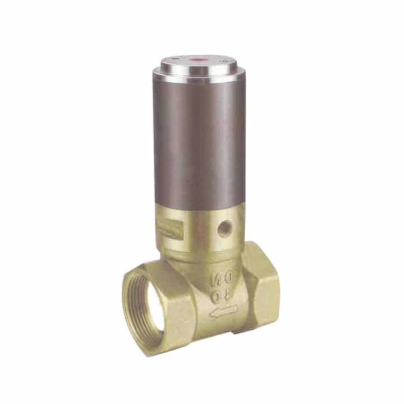
An actuator-operated seat valve illustrates the poppet principle, but its process-media duty and ratings should not be transferred to a compact pneumatic directional valve.
Does a poppet valve always seal better than a spool valve?
Parker advises considering a two-way poppet when an application requires leakage below 5 drops per minute, because its referenced spool cartridge has clearance-related leakage (Parker, accessed 2026). That is a specific product comparison, not proof that every spool leaks excessively or every poppet provides bubble-tight shutoff.
Leakage begins with the sealing design. A metal-clearance spool needs a running gap, so some internal bypass can be inherent. An elastomer-sealed spool may reduce leakage substantially, but the seals add friction and wear surfaces. Cartridge-seal spool designs create another performance class. Asking only “is it a spool?” misses those differences.
A poppet can create firm contact at the seat, which often suits shutoff duty. Yet seat damage, embedded particles, reverse pressure, incorrect flow direction, insufficient closing force, or incompatible elastomers can still produce leakage. Some poppets are pressure assisted; others are pressure balanced or subject to opening forces that must be overcome by the operator.
Specify leakage as a number and a test condition:
- permitted internal leakage in the de-energized and energized states
- inlet and outlet pressure during the test
- flow direction
- air or process medium
- temperature and seal material
- new-valve acceptance and end-of-life threshold
If the circuit must hold downstream pressure, isolate a vacuum volume, or stop a process medium, obtain the supplier’s leakage rating for that exact flow direction. Labels such as “excellent sealing” are not acceptance criteria.
Which design switches faster and more consistently?
Parker lists a response-time value of 50 for one direct-acting, two-position spool cartridge, while Festo explains that a poppet’s shorter actuation stroke can also produce short switching times (Parker; Festo, accessed 2026). Therefore response must be compared by product, voltage, pressure, temperature, and measurement definition, not architecture alone.
Response time includes more than the main element’s travel. Coil current rise, armature movement, pilot filling or exhausting, pressure force, spring force, spool friction, poppet adhesion, and downstream pneumatic volume can all contribute. The pneumatic solenoid-valve operating guide explains how those electrical and pneumatic stages interact.
Consistency can matter more than the fastest single cycle. Clippard lists consistent response as a reason a spool may suit certain applications, while also describing poppets as short-stroke, fast-response devices (Clippard, accessed 2026). The two statements aren’t contradictory. One addresses repeatability under particular conditions; the other addresses a geometric advantage.
Compare these datasheet fields together:
| Response input | Why it matters |
|---|---|
| Energizing and de-energizing time | The two directions may differ |
| Minimum and maximum pressure | Pressure can change pilot and main-stage forces |
| Voltage tolerance and coil power | Electrical force changes with supply conditions |
| Temperature range | Coil resistance, lubricant, and elastomer behavior change |
| Test medium and flow state | A no-flow bench result may not represent the machine |
| Cycle rate or duty rating | Heat and recovery time may limit repeated switching |
What if the catalog says only “fast response”? Ask for the test method or measure the full command-to-pressure response on the machine. That is the timing the actuator actually experiences.
How do flow capacity and pressure drop compare?
ISO 6358-1:2013 defines steady-state testing for pneumatic components with fixed or variable internal flow paths, and Amendment 2 added measurement-uncertainty evaluation in April 2026 (ISO 6358-1; ISO Amendment 2, 2026). Compare spool and poppet candidates using compatible flow coefficients and test conditions, not port size alone.
The internal path controls pressure loss. Spool-valve flow may turn through several body passages and windows around the lands. Poppet flow expands through an annular seat opening and then through the body. Either design can be optimized for high flow, and either can be restricted by a small pilot passage, connector, muffler, manifold, or fitting.
Cv, Kv, sonic conductance C, critical pressure ratio b, and catalog nominal flow are not automatically interchangeable. Check the reference pressure, upstream and downstream conditions, standard temperature, test medium, and direction. The site’s sonic-conductance and critical-pressure-ratio guide covers the ISO 6358 terms in more detail.
ISO 6358-3:2014 covers calculation of overall system flow characteristics from components and piping with known characteristics, including subsonic and choked flow (ISO 6358-3, confirmed 2025).
Use this sequence:
- Calculate the actuator or process flow requirement.
- Set the maximum acceptable pressure loss across the valve and manifold.
- Compare the correct flow path, including supply-to-work and work-to-exhaust.
- Check normal, reverse, and transitional flow directions.
- Include fittings, tubes, silencers, and quick-exhaust devices in the system review.
A valve with a larger catalog flow number may still create the slower cylinder if its exhaust path, manifold sub-base, or silencer is the real restriction. Compare the installed flow chain, not just the inlet rating.
What do crossover, port count, and flow direction change?
A 5/2 valve has 5 ports and 2 switching positions, but its brief intermediate connections depend on land overlap, seat timing, and the operator mechanism. Festo notes that some poppet arrangements can momentarily connect supply, work, and exhaust paths during movement, while piston-spool geometry can be designed to control overlap (Festo, 2018).
Transitional behavior matters in machines that must avoid pressure spikes, unintended cylinder movement, vacuum loss, or cross-port exhaust. The steady-state symbol shows the commanded positions. It may not reveal every internal connection during the shift. Pilot-stage behavior is a separate check covered in the pilot-operated valve guide.
Spool land geometry can provide positive overlap, negative overlap, or a designed crossover pattern. Positive overlap briefly blocks paths; negative overlap may briefly connect them. Poppet arrangements can provide closed crossover when one seat closes before another opens, but multi-poppet sequencing can also produce other states. Ask the manufacturer rather than inferring the answer from the generic valve type.
Flow direction matters too. Parker’s referenced two-way spool cartridge blocks both directions but still gives a preferred direction because flow forces act on the spool. Many poppet valves resemble check-valve geometry and may have a required inlet direction. Reverse pressure can change opening force, sealing, or permitted leakage.
Before replacing one architecture with the other, confirm:
- ISO port function and valve symbol
- normally closed, normally open, monostable, or bistable behavior
- energized and de-energized flow paths
- center condition for three-position valves
- preferred and permitted flow directions
- crossover state during switching
- response after loss and restoration of power or pilot pressure
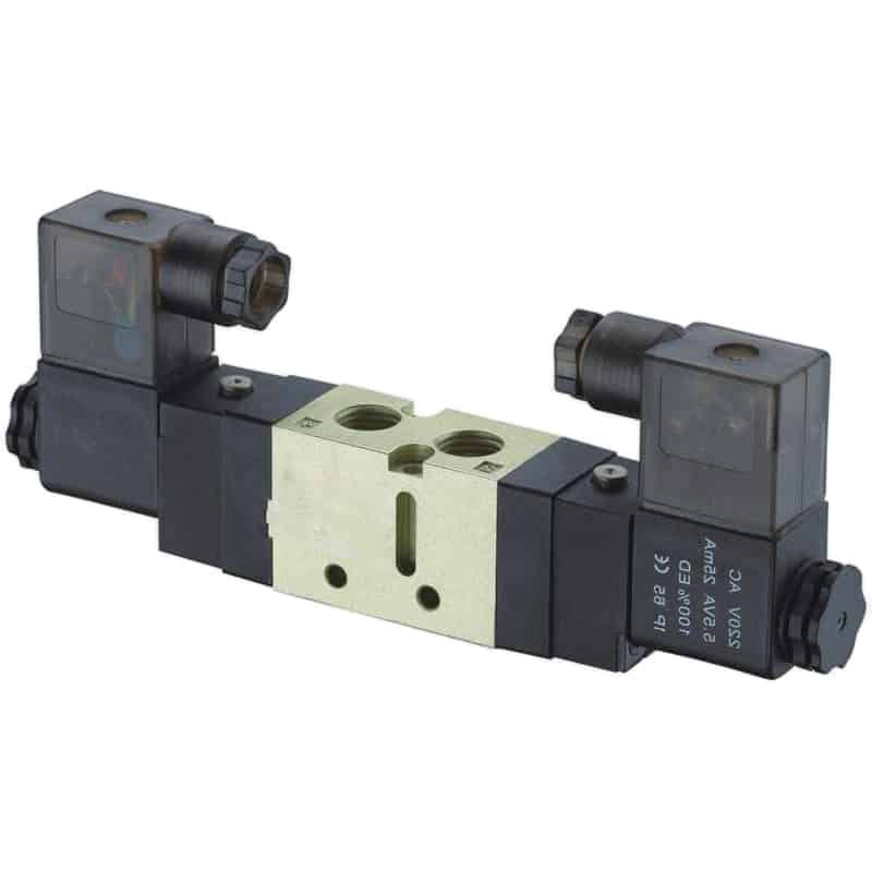
A multiport directional valve must be selected by its complete symbol, port function, flow data, actuation method, and failure state. Its exterior does not prove the internal spool or poppet construction.
Which valve tolerates contamination and long cycle life better?
Festo describes a self-cleaning effect at some poppet seats and also identifies piston-spool cartridge seals as a lower-leakage, higher-pressure development within the spool family (Festo, 2018). These refinements show why contamination tolerance and life must be tied to the exact seal and failure mode.
A particle can hold a poppet off its seat and create a leak. Flow may flush a loose particle away, but a hard particle can also cut an elastomer or damage a seat. In a spool valve, debris can score the bore, cut a sliding seal, increase friction, or prevent full travel. Neither outcome supports running poor-quality air without the specified filter and condensate control.
Maintenance intervals such as 12 months or 3 years cannot be assigned from architecture alone. Cycle count, switching frequency, differential pressure, media, lubrication policy, temperature, vibration, coil heating, seal chemistry, and contamination load all influence service life. For a main-spool-specific review, see the pneumatic pilot-operated directional valve guide.
For a defensible maintenance plan, record:
- manufacturer air-quality and filtration requirements
- permitted lubrication policy
- seal and body material compatibility
- rated cycle life under stated conditions
- leakage and response-time acceptance limits
- inspection or replacement instructions
- observed failure mode and returned-part findings
Don’t replace valves on a generic calendar if condition and cycle data support a better interval. Conversely, don’t extend the interval because the architecture is described as “self-cleaning.” Use supplier instructions and machine evidence.
When should you select a spool valve or a poppet valve?
Clippard identifies vacuum, downstream pressure holding, selector circuits, and consistent response as situations favoring certain spool designs, while listing low leakage, short stroke, and closed-crossover behavior among possible poppet advantages (Clippard, accessed 2026). Treat those as screening criteria, then verify the selected part’s ratings.
Choose a spool candidate when the circuit needs several ports and positions in a compact body, a particular center condition, bidirectional paths, or a documented vacuum capability. A spool can also be attractive for a manifold containing many directional functions. Confirm leakage and crossover if the circuit traps pressure.
Choose a poppet candidate when low shutoff leakage, a short mechanical stroke, seat-material flexibility, or a particular closed-crossover sequence is central to the application. Confirm required flow direction, pressure balance, pilot conditions, and reverse-pressure behavior.
| Application requirement | First design to investigate | Data that decides |
|---|---|---|
| 5/2 or 5/3 cylinder directional control | Often spool | Flow paths, center state, exhaust flow, leakage |
| Low-leak two-way shutoff | Often poppet | Published leakage, flow direction, seat material |
| Vacuum switching | Often a rated spool or vacuum-specific poppet | Vacuum rating and leakage test |
| Dirty compressed air | Neither without air-quality review | Filter rating, condensate control, seal failure mode |
| High cycle rate | Either | Rated life, response drift, coil duty, temperature |
| Proportional flow | Purpose-built proportional valve | Hysteresis, control curve, feedback, leakage |
| Safety-related function | Architecture alone is insufficient | Risk assessment, diagnostics, fault response, validated data |
The final choice is often hybrid: a spool directional valve handles actuator routing while a separate poppet shutoff or isolation valve handles low-leak supply isolation. Good circuit architecture assigns each component the job its datasheet actually proves.
What must be checked before replacing one design with the other?
ISO 6358-3:2014 uses known component and piping characteristics to calculate system flow, so a replacement should be checked as part of the connected circuit rather than as one matching thread size (ISO, confirmed 2025). A mechanically compatible valve can still change pressure loss, exhaust behavior, crossover, leakage, or safe state.
Use the existing valve’s full ordering code and datasheet as the baseline. Photograph the label, record the symbol, identify every port, and note the actual wiring. Then document pressure at the valve, medium, temperature, required flow, coil voltage and power, connector, manual override, duty cycle, and mounting pattern.
The replacement review should answer these questions:
- Are port functions and normal positions identical?
- Is the permitted flow direction the same?
- Does the new valve meet supply-to-work and work-to-exhaust flow demand?
- Are minimum pressure, maximum pressure, vacuum, and pilot requirements compatible?
- Is internal leakage acceptable in every commanded state?
- Does crossover create an unintended pressure or exhaust path?
- Are response time, duty cycle, and coil temperature acceptable?
- Do voltage, connector, suppression, ingress protection, and hazardous-area approvals match?
- Will the machine move safely after power or air is lost and restored?
- Can maintenance obtain seals, coils, manifolds, and complete replacement valves?
Bench-test the replacement where a wrong transitional state could move an actuator or release pressure. On the machine, begin with the hazard zone controlled, reduce speed or pressure where the procedure permits, and verify every normal and fault state before returning to production.
FAQs About Spool vs. Poppet Valve Selection
ISO 6358-1 received a 2026 amendment covering measurement-uncertainty evaluation, reinforcing that comparable test conditions matter when flow numbers are used for selection (ISO, 2026). These answers separate architecture-level tendencies from product-level guarantees.
Are poppet valves always leak-free?
No. A poppet’s seat contact can provide low shutoff leakage, but particles, seat damage, incompatible seals, reverse pressure, temperature, and insufficient closing force can create leakage. Specify a permitted leakage value, pressure, medium, temperature, and flow direction, then confirm the exact model’s published test data.
Are spool valves always faster than poppet valves?
No. Direct spool products can respond quickly, while the short stroke of some poppets can also support fast switching. Pilot volume, pressure, coil characteristics, friction, temperature, and downstream volume affect the result. Compare energized and de-energized response data under conditions close to the application.
Can a spool valve hold a cylinder in position?
A closed-center spool can block actuator ports, but internal leakage and cylinder seal leakage may still allow drift. It is a directional-control state, not automatically a safety-rated load-holding method. If unintended movement creates a hazard, use a risk assessment and separately validated restraint or holding strategy.
Which design is better for contaminated compressed air?
Neither design makes filtration optional. Some poppet seats can shed loose debris, while spool sliding surfaces may be sensitive to scoring; a particle can also damage a poppet seat. Follow the valve’s required air-quality class, filtration, condensate control, lubrication policy, and seal-material limits.
Can a poppet valve directly replace a spool valve?
Only after verifying every port, position, flow direction, pressure limit, pilot requirement, leakage rating, response time, crossover state, coil, connector, mounting dimension, and safe state. Many spool valves provide multiport directional functions that a two-way poppet cannot reproduce without additional valves or a different circuit.
Final selection checklist
Parker’s 5-drops-per-minute guidance applies to one two-way cartridge comparison, not every pneumatic valve (Parker, accessed 2026). Keep that level of specificity throughout the selection: architecture narrows the field, while the model datasheet and application test make the decision.
- Required valve symbol, ports, positions, and center state
- Spool or poppet main element, plus direct or pilot actuation
- Normal, reverse, and transitional flow paths
- Minimum, normal, and maximum pressure
- Vacuum and reverse-pressure requirements
- Permitted internal and external leakage
- Cv, Kv, or ISO 6358 flow data under matching conditions
- Energizing and de-energizing response time
- Switching frequency, duty cycle, and life rating
- Air quality, filter, condensate, lubrication, and material compatibility
- Coil voltage, power, connector, suppression, and enclosure rating
- Mounting, manifold, spare-part, and replacement constraints
- Fault response after loss and restoration of air or power
There is no universal winner. Select the spool or poppet valve whose documented flow paths, leakage, timing, materials, and fault behavior match the machine.
Sources
- Festo, “Piston spool valves and poppet valves: A technical comparison of available solenoid valves,” 2018. https://www.festo.com/media/cms/media/editorial/downloads/White_Paper_-_Piston_spool_valves_and_poppet_valves_180910.pdf
- Parker Hannifin, “2 Way Spool Type Solenoid Valve,” accessed 2026. https://ph.parker.com/ProductDisplay?catalogId=10001&categoryId=61145&errorViewName=ProductDisplayErrorView&langId=-1&parentCatId=61145&parentProductId=2187777&productId=2187873&storeId=10152&urlRequestType=Base
- Parker Hannifin, “Pneumatic Valve Fundamentals.” https://www.parker.com/parkerimages/pneumatic/serv/VAL-TEC-16.pdf
- Clippard, “Comparing Poppet Valves vs. Spool Valves,” accessed 2026. https://www.clippard.com/cms/node/328
- ISO, “ISO 6358-1:2013 Pneumatic fluid power, Determination of flow-rate characteristics, Part 1.” https://www.iso.org/standard/56612.html
- ISO, “ISO 6358-1:2013/Amd 2:2026, Evaluation of measurement uncertainty.” https://www.iso.org/standard/88078.html
- ISO, “ISO 6358-3:2014, Method for calculating steady-state flow-rate characteristics of systems.” https://www.iso.org/standard/56616.html