

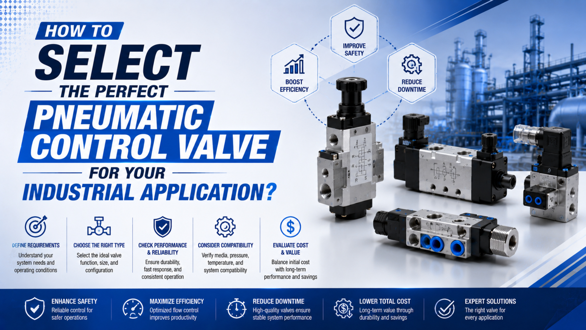
The right pneumatic control valve is the one that provides the required port function and failure response, passes enough air through both the supply and exhaust paths, shifts within the timing budget, and matches the application’s pressure, pilot, electrical, environmental, mounting, and reliability requirements. No single valve is perfect outside a defined operating point.
Start with the actuator and machine state, not a preferred port size or Cv number. A valve that looks generous on flow can still fail the application because it has the wrong normal state, needs unavailable pilot pressure, vents a suspended load, shifts too slowly, or cannot tolerate the installed air quality.
Key Takeaways
- Select valve function and loss-of-energy behavior before selecting flow capacity.
- Size from the actuator’s target motion and check supply and exhaust paths separately.
- Compare Cv, Kv, nominal flow, or ISO 6358 data only under stated test conditions.
- A 5/3 closed center can drift and is not a certified load-holding device.
- Approve the exact ordering code only after an installed-state acceptance test.
What Must Be Defined Before You Select a Valve?
Define the motion, load, energy state, and control interface before opening a valve catalog. The phrase “operate a cylinder” is not enough to choose a 3/2, 5/2, or 5/3 function, much less a complete part number.
Record these application inputs:
- Actuator type: single-acting cylinder, double-acting cylinder, rotary actuator, gripper, air motor, vacuum device, or process actuator.
- Required motion: extend, retract, rotate, clamp, blow off, isolate, vent, modulate, or hold within a stated tolerance.
- Pressure states: minimum dynamic inlet pressure, maximum supply pressure, downstream or exhaust pressure, and permitted pressure loss.
- Flow demand: bore, rod diameter, stroke, target stroke time, simultaneous consumers, and duty cycle.
- Loss-of-energy response: required behavior after command loss, electrical loss, pilot-pressure loss, main-air loss, and repressurization.
- Control interface: manual, mechanical, pneumatic pilot, solenoid, proportional command, or fieldbus valve terminal.
- Installation constraints: individual or manifold mounting, port standard, tube size, connector, voltage, enclosure, temperature, vibration, and service access.
- Acceptance limits: maximum switching delay, timing variation, leakage, drift, residual pressure, restart movement, and permitted failure criteria.
The selection becomes traceable when every catalog decision points back to one of those requirements. It becomes guesswork when “same thread size” or “higher flow” is used as the whole specification.
Which Valve Function Matches the Actuator?
Select the port and position function from the required flow paths. ISO 1219-1 establishes rules for fluid-power graphical symbols, so the symbol is a better starting point than a marketing name (ISO 1219-1:2012, retrieved 2026-07-27).
| Valve function | Typical use | Selection question |
|---|---|---|
| 2/2 | Start or stop one flow path | Should the path be normally closed or normally open? |
| 3/2 | Single-acting actuator, pilot signal, blow-off, venting | What must outlet port 2 do when the operator is released? |
| 5/2 | Reverse a double-acting actuator | Should loss of the command return the valve or preserve the last state? |
| 5/3 | Add a defined center state for a double-acting actuator | What must happen to supply, both working ports, and both exhaust paths in center? |
| Proportional pressure or flow valve | Continuously vary a pneumatic variable | What command, feedback, accuracy, hysteresis, and fail state are required? |
A single-solenoid spring-return valve is normally monostable: it returns to a defined position after its electrical command is removed, provided its spring and pilot conditions allow it. A double-solenoid or double-pilot valve is commonly bistable: it can preserve the last spool position after one signal disappears. That memory can be useful for sequencing but dangerous when the risk assessment expects automatic return.
The 3/2 versus 5/2 application comparison covers port-function selection in more detail. After choosing the generic symbol, verify the exact manufacturer’s symbol and ordering code. Port numbers, normal state, return method, crossover behavior, pilot source, and manual-override behavior must all match.
Direct acting or pilot operated?
A direct-acting valve moves its main sealing element directly from the operator. It can often work from zero differential pressure, but coil force limits how large a flow path it can open.
A pilot-operated valve uses pressure to shift the main stage. This supports greater flow for a compact solenoid, but it creates a minimum pilot-pressure requirement and another flow path that can fail. Internal pilot air depends on the valve’s supply conditions. External pilot air can support unusual main-pressure or vacuum arrangements, but only if the pilot circuit remains available and correctly exhausted.
Do not infer minimum pressure from the port size. The minimum pilot-pressure calculation guide explains the force balance; the selected product’s datasheet remains the final authority. Emerson’s AVENTICS selector demonstrates why this check belongs in the purchasing specification: variants within one product family differ by valve function, actuation, flow, minimum working pressure, voltage, and pilot arrangement (AVENTICS Series 490/579/589, retrieved 2026-07-27).
How Much Flow Must the Installed Valve Path Pass?
Size from the actuator’s target motion, then verify the complete path at the lowest credible dynamic supply pressure. Cylinder bore, rod diameter, stroke, target time, direction, and working pressure establish the starting free-air demand. Simultaneous actuators and peak acceleration can raise the manifold demand above one cylinder’s average consumption.
The calculator provides a pre-selection demand, not a stroke-time guarantee. The final speed also depends on:
- pressure available at the valve while other consumers operate;
- valve supply-to-working-port capacity;
- valve working-port-to-exhaust capacity;
- manifold supply and common-exhaust galleries;
- fitting and tube inside diameter and length;
- meter-out or meter-in flow controls;
- silencers, quick-exhaust valves, and cylinder cushions;
- load ratio, friction, guide alignment, and temperature.
Check extension and retraction separately. A single-rod cylinder has different chamber volumes and effective areas, and the controlling restriction can switch from the supply path to the exhaust path. A valve with adequate inlet flow can still limit speed through a smaller exhaust passage or a restrictive silencer.
The specific-stroke-time valve-sizing guide covers the detailed calculation and commissioning sequence. For this selection article, the essential rule is simpler: derive peak demand first, then compare that demand with published flow data under compatible pressure and reference conditions.
How Should Cv, Kv, Nominal Flow, and ISO 6358 Data Be Compared?
Cv and Kv are liquid-based flow coefficients. They can help compare geometrically similar valves when the manufacturer states the applicable convention, but a fixed multiplication does not turn either coefficient into a complete compressed-air sizing result.
ISO 6358-1 specifies steady-state test methods for pneumatic components using compressible fluids. Its flow characterization accounts for subsonic and choked regimes rather than assuming one universal downstream-to-upstream pressure boundary (ISO 6358-1:2013, retrieved 2026-07-27).
When catalogs use different ratings, document:
- test standard and edition;
- upstream and downstream absolute pressure;
- inlet temperature;
- gas and reference-state convention;
- flow direction;
- sonic conductance or effective conductance;
- critical back-pressure ratio when supplied;
- Cv, Kv, effective area, or nominal-flow definition;
- valve position and port path tested.
Do not convert a catalog Cv into sonic conductance with an unexplained constant and treat the answer as manufacturer data. Do not size compressed air with the liquid relationship alone. The Cv and pneumatic valve-sizing guide explains what each rating can and cannot establish.
The most useful comparison value is often not the largest number in either catalog. It is the predicted or tested flow through the same functional path at the same inlet pressure, outlet pressure, temperature, and reference state. If those conditions differ, normalize the comparison or ask each supplier for an application-specific selection.
Which 5/3 Center Condition Matches the Required Machine State?
A 5/3 valve’s middle position defines the normal connection among supply port 1, working ports 2 and 4, and exhaust ports 3 and 5. It does not, by itself, define a safe machine state.
| Center condition | Typical port state | What it does not guarantee |
|---|---|---|
| Closed center | Supply and working ports blocked | Zero leakage, zero drift, or safe vertical-load holding |
| Exhaust center | Supply blocked; both working ports connected to exhaust | Controlled load motion or zero residual pressure at the cylinder |
| Pressure center | Both working ports supplied | Force balance, zero movement, or low neutral air consumption |
Closed center traps compressible air. External load, temperature change, valve leakage, cylinder seal leakage, and tube expansion can still move the actuator. Exhaust center can release a clamp or allow gravity motion. Pressure center applies pressure to unequal effective areas in a single-rod cylinder and can create a net extension force.
For a suspended or hazardous load, select and validate a separately rated restraint such as a mechanical brake, rod lock, or application-approved load-holding circuit. ISO 4414 addresses hazards at pneumatic-system level; it does not make a standard directional-valve center a safety function by label alone (ISO 4414:2010, retrieved 2026-07-27).
Use the dedicated 5/3 center-condition selection guide to evaluate drift, residual pressure, force bias, pilot loss, supply loss, and restart movement.
What Electrical, Pneumatic, and Mechanical Interfaces Must Match?
After function and flow, build a compatibility matrix for the exact part number. A valve body can fit the manifold while its coil, pilot, pressure, or exhaust behavior remains wrong.
Electrical and control data
- rated voltage and permitted tolerance;
- AC frequency where applicable;
- steady, inrush, or peak-and-hold power;
- connector type and pinout;
- surge suppression and its effect on release time;
- polarity and indicator options;
- coil duty and thermal limits;
- PLC output current and off-state leakage;
- fieldbus node, diagnostics, and safe output state.
Pneumatic data
- minimum and maximum operating pressure;
- internal or external pilot arrangement;
- pilot-pressure range;
- working and pilot media;
- required filtration, lubrication policy, and dew-point limits;
- permitted exhaust backpressure;
- leakage specification;
- flow direction and vacuum compatibility.
Mechanical and environmental data
- individual, sub-base, NAMUR, or manifold mounting;
- NPT, BSPT, BSPP/G, metric, or push-in connection;
- port and tube inside diameter;
- ambient and media temperature;
- enclosure and ingress-protection rating;
- vibration and shock limits;
- corrosion, washdown, cleanroom, food-contact, or hazardous-location requirements;
- seal, body, and lubricant compatibility.
A Festo 5/3 valve datasheet, for example, lists valve function, direct actuation, operating pressure, pilot arrangement, pilot-pressure range, standardized flow, ISO 6358 C and b values, switching times, air-quality requirement, temperature, and electrical limits as separate specifications (Festo VL-5/3B datasheet, retrieved 2026-07-27). That is the level of detail an approved replacement must match.
The pneumatic valve port-thread guide covers thread identification and sealing. Treat port size as an interface specification, not proof of internal orifice size or flow capacity.
How Should Response Time and Reliability Evidence Be Evaluated?
Separate valve switching time from machine response. Electrical delay, pilot filling, spool travel, line-volume pressurization, exhaust decay, actuator breakaway, load acceleration, and sensor recognition occur in sequence. A catalog value measured on a bare valve under favorable pressure is not the loaded cylinder’s stroke time.
For a synchronization-sensitive machine, specify:
- response-time definition and measurement points;
- energizing and de-energizing limits;
- maximum value, not only a typical value;
- cycle-to-cycle variation;
- test pressure, temperature, voltage, pilot condition, and load;
- end-of-line and installed-machine acceptance method.
The solenoid-valve response-time guide explains how to build that timing budget.
Reliability claims need the same discipline. ISO 19973-2 provides test procedures, reporting methods, equipment, and threshold levels for pneumatic directional control valves, and expresses their life variable in cycles (ISO 19973-2:2015, retrieved 2026-07-27). A credible comparison therefore includes:
- exact valve configuration and sample quantity;
- test pressure, cycling frequency, temperature, voltage, and media quality;
- load or downstream volume;
- failure definition and measurement threshold;
- failures and suspended units;
- confidence method and reported life metric;
- evidence that accelerated conditions preserve the field failure mechanism.
Do not divide a laboratory cycle count by annual production cycles and present the quotient as guaranteed calendar life. NIST describes accelerated-life projection as a model-fitting problem across controlled stress cells and warns against stresses high enough to introduce new failure mechanisms (NIST accelerated life tests, retrieved 2026-07-27).
Weibull analysis can describe failure-time data when the distributional assumption and data support it; it does not create reliability evidence from an unsupported cycle claim. NIST identifies the Weibull shape and scale parameters and recommends checking the model against actual failure data (NIST Weibull model, retrieved 2026-07-27).
In our experience, reviewing the failure criterion is the fastest way to expose an incomplete valve-life claim. “Tested to a large cycle count” may mean no coil burnout, while the application may fail much earlier from leakage, delayed switching, pressure loss, or timing variation. The acceptance threshold must match the machine consequence.
What Should Be Included in the Valve RFQ and Acceptance Test?
Send suppliers one operating-point sheet instead of asking for a “high-flow, long-life valve.” The sheet should let another engineer reproduce the selection without guessing.
| RFQ field | Required entry |
|---|---|
| Valve function | Complete ISO-style symbol, normal state, number of ports and positions |
| Actuator and load | Type, bore, rod, stroke, load direction, mass, guide arrangement |
| Motion target | Extend/retract time, dwell, switching frequency, simultaneous demand |
| Pressure | Minimum dynamic inlet, maximum supply, downstream/exhaust condition |
| Flow evidence | Required free-air demand and accepted catalog/test convention |
| Failure behavior | Command loss, coil loss, pilot loss, supply loss, restart |
| Actuation | Direct or pilot operated, internal/external pilot, mono-/bistable |
| Electrical | Voltage, tolerance, connector, suppression, output interface |
| Installation | Mounting, manifold, port threads, tube size, silencer |
| Environment | Air quality, temperature, IP rating, vibration, chemicals, approvals |
| Performance limits | Response, variation, leakage, drift, residual pressure |
| Reliability evidence | Test method, conditions, samples, failures, confidence, thresholds |
Require the supplier to return the complete ordering code, symbol, datasheet revision, flow basis, pilot requirements, and every assumption used. Then verify the installed assembly at the lowest supply pressure, highest expected demand, and worst credible temperature.
The restart test often reveals more than the neutral test. A cylinder can remain nearly still while both chambers are trapped, then jump when one chamber reconnects to supply and the other reconnects to exhaust. Set a maximum permitted restart displacement and verify actuator position before automatic motion resumes.
Pneumatic Control Valve Selection FAQs
Can I select a pneumatic valve from port size alone?
No. Port thread identifies the connection, not the smallest internal passage, spool path, exhaust capacity, pilot requirement, or tested flow characteristic. Compare the exact supply and exhaust paths under stated pressure conditions, then verify tube, fitting, manifold, and silencer restrictions.
Is a higher Cv always better?
No. A higher compatible flow rating can reduce pressure loss, but it cannot correct the wrong valve function or pilot arrangement. An unnecessarily large valve may also increase cost, manifold size, air volume, switching energy, and low-speed control sensitivity. Select sufficient installed capacity with justified margin.
Should a 5/2 valve be single-solenoid or double-solenoid?
Choose from the required loss-of-command behavior. A spring-return single-solenoid valve normally moves to a defined state when its coil is de-energized, subject to pilot and pressure requirements. A double-solenoid valve commonly preserves its last state. Confirm the exact symbol and test electrical, pilot, and main-air loss separately.
Can a closed-center 5/3 valve safely hold a vertical cylinder?
Not by itself. Trapped air is compressible, and leakage through the valve, cylinder, tubing, or fittings can cause drift. A suspended or hazardous load normally needs a separately rated mechanical restraint or validated load-holding architecture plus controlled depressurization and restart.
How should two valve suppliers be compared?
Give both suppliers the same actuator data, dynamic pressures, target motion, flow path, air quality, environment, electrical interface, fault-state requirements, and acceptance limits. Compare the returned ordering code and flow evidence under equivalent test conditions; then validate both candidates on the installed circuit.
Sources and Technical References
ISO: ISO 1219-1:2012, rules for fluid-power graphical symbols used on components and circuit diagrams. Retrieved 2026-07-27.
ISO: ISO 6358-1:2013, steady-state flow-rate test methods for pneumatic components using compressible fluids. Retrieved 2026-07-27.
ISO: ISO 19973-2:2015, reliability assessment by testing for pneumatic directional control valves. Retrieved 2026-07-27.
ISO: ISO 4414:2010, general rules and safety requirements for pneumatic systems and components. Retrieved 2026-07-27.
Festo: VL-5/3B-3/8-B directional-valve datasheet, model-specific function, pressure, pilot, flow, timing, media, and environmental data. Retrieved 2026-07-27.
Emerson AVENTICS: Series 490/579/589 directional control valves, selectable actuation, switching principle, flow, pressure, voltage, and connection variants. Retrieved 2026-07-27.
NIST: Accelerated life tests and Weibull lifetime model, accelerated-test planning, projection conditions, and failure-time distribution concepts. Retrieved 2026-07-27.