

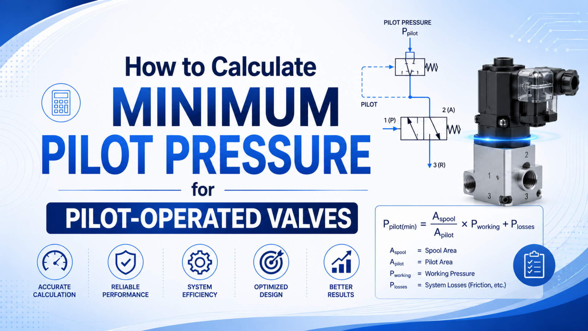
Minimum pilot pressure is not one universal percentage of main-line pressure. Start with the exact valve’s pilot-pressure range or minimum operating differential, then subtract losses between the pilot source and pilot port. The result must remain above the published minimum while the valve is shifting, not merely while the circuit is idle.
That distinction prevents a common category error. A pilot-operated valve can be an internally piloted diaphragm valve, an externally air-piloted spool valve, or another two-stage design. Each architecture places different forces and pressure conditions on its pilot stage.
Key Takeaways
- Parker examples span 25 to 45 psi.
- Internal-pilot designs may specify minimum supply pressure or differential pressure instead of a separate pilot signal.
- Measure dynamic pressure at the pilot port during the worst machine demand, confirm shift and return time, and keep every reading within the selected valve’s published minimum and maximum.
What Is Minimum Pilot Pressure Really Measuring?
Parker lists a 30 psi minimum pilot pressure for one four-way, double-air-pilot valve with a 30 to 115 psi operating range. This threshold applies at the signal ports for that product. It is not a reusable area-ratio rule for every pilot-operated valve (Parker Pneumatic Control Catalog, 2007).
Minimum pilot pressure is the lowest pressure at the specified pilot port that the manufacturer accepts for reliable switching under stated conditions. A complete specification also sets the maximum pilot pressure. It may also limit main pressure, media, temperature, valve function, return method, mounting, and minimum differential pressure.
Keep these pressure terms separate:
| Term | Where it applies | What to verify |
|---|---|---|
| Main operating pressure | Supply and working passages of the main valve | Published operating range for the selected function. |
| Pilot-source pressure | Regulator, header, or pilot-signal valve inlet | Lowest pressure during machine demand. |
| Pilot-port pressure | Port 12, 14, or product-specific actuator port | Dynamic pressure while the main stage shifts. |
| Minimum differential pressure | Pressure difference across an internally piloted main stage | Published minimum for that media and flow direction. |
| Drop-out or return pressure | Pilot pressure at which a spring-return valve resets | Required de-energized behavior and residual backpressure. |
Gauge pressure is normally used for pneumatic catalog ratings unless the product documentation explicitly says otherwise. Vacuum service may require absolute pressure. Record the reference convention before converting units or comparing catalog data.
The real engineering question is not “What safety factor should multiply main pressure?” It is “Which published threshold applies at which port, and what is the lowest pressure that remains there during the switching event?”
Which Valve Architecture Are You Calculating?
SMC’s VQC1000/2000 manual gives internal-pilot minimums of 0.1 MPa for some metal-seal valves, 0.15 MPa for some rubber-seal versions, and 0.2 MPa for three-position versions. One valve family therefore has several thresholds before tubing losses are considered (SMC VQC1000/2000 Manual, 2026).
Identify the architecture before writing an equation:
| Architecture | What operates the main stage | Appropriate selection method |
|---|---|---|
| Direct acting | Solenoid, lever, plunger, or mechanical element acts directly | No separate pilot-pressure calculation. |
| Internally piloted spool valve | Main supply feeds an internal pilot gallery | Check minimum operating pressure for the exact spool and seal configuration. |
| Externally piloted spool valve | Separate pressure enters pilot ports 12/14 or equivalent | Check the external-pilot range and calculate delivery losses. |
| Pilot-operated diaphragm or poppet valve | Differential pressure and a small pilot passage move the main closure | Check minimum operating differential and permitted flow direction. |
| Air-operated process valve | External air acts on a piston or diaphragm actuator | Use the actuator’s pilot-pressure chart or verified force balance. |
The difference between direct-acting and pilot-operated valves matters here. A direct-acting solenoid valve may control the external pilot signal, but that does not turn the small signal valve itself into a pilot-operated main valve.
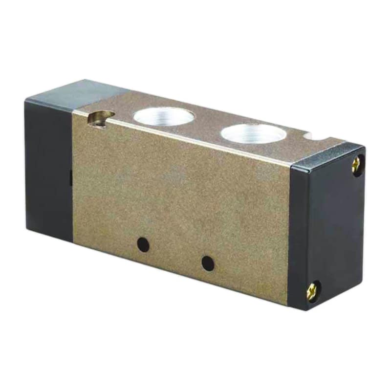
An air-piloted directional valve still requires its own model-specific pressure range, port map, and return-function data.
How Do You Calculate Pressure Available at an External Pilot?
Parker’s N Series chart requires 35 psi external pilot pressure at 25 psi main pressure for its 3/8-inch basic valve, but 65 psi at 100 psi main pressure. The changing requirement shows why the selected model’s pressure table must supply the threshold (Parker 0600P-E N Series, 2018).
For an external pilot, calculate the lowest pressure that can reach the valve during switching:
Here, is the lowest regulated source pressure during the machine cycle. The two pressure-drop terms cover the pilot-signal valve and the downstream tubing, fittings, silencers, or restrictions. Use consistent gauge-pressure units throughout this budget.
The acceptance condition is:
That term is the manufacturer’s minimum for the exact part number, function, seal type, and main-pressure condition. Do not use a generic fraction. Also verify that the highest possible pilot pressure remains below the catalog maximum.
When Is a Force-Balance Equation Valid?
Parker’s Directair 2 instructions list a 1.5 psi minimum for a diaphragm operator and 20 psi for a pilot operator on related valves. Actuator construction changes the force requirement. That difference exists even before the main process load is added (Parker Directair 2 Instructions, 2025).
A force balance is appropriate only when the manufacturer’s drawing or validated design data identifies the effective pilot area and all opposing forces:
is the return-spring force at the relevant travel, covers seal and guide resistance, is the net force created by process pressure on the actual closure geometry, and is effective pilot area. Pressure is force divided by area, so use compatible units.
Do not automatically substitute for . A pressure-balanced spool can cancel much of the static main-pressure force, while a poppet or diaphragm can expose a different effective area depending on flow direction and seat geometry. Guessing that area can make a dimensionally valid equation physically wrong.
For catalog valves, the published minimum normally remains the controlling value because it already reflects proprietary geometry, return springs, seals, manufacturing tolerance, and the manufacturer’s test method.
How Does Internal Piloting Change the Calculation?
An ASCO L145 pilot-operated valve specifies a 0.4 to 8 bar differential-pressure range for gases and liquids in the selected configuration. Its 0.4 bar minimum applies across the main valve. It is not an external pilot-port setting (ASCO L145 Product Specification, 2026).
An internally piloted valve takes pilot energy from the main inlet. Selection therefore centers on the manufacturer’s published minimum operating pressure or minimum pressure differential for the chosen function and flow direction:
If the catalog requires a minimum differential, the actual must remain above it while the valve opens. For example, high downstream pressure can block switching. A nearly equalized system can do the same even when inlet pressure looks adequate.
Zero-differential pilot-operated designs exist, but that feature belongs to specific constructions. Do not infer it from the words “pilot operated.” When a valve must operate from vacuum, very low main pressure, or an unusual pressure direction, an external-pilot version may be the correct choice.
How Do Pressure Drop and Response Time Affect the Result?
Parker’s H Series Micro table lists minimum pilot pressures from 25 to 45 psi by valve number and a 120 psi maximum. A shared manifold name does not imply one threshold. Adequate static pressure also does not prove that the pilot chamber fills fast enough (Parker H Series Micro, 2025).
Pilot tubing, fittings, the signal valve, exhaust restriction, and pilot-chamber volume form a small pneumatic flow system. Static pressure can mislead. For example, a long narrow tube can eventually show full pressure yet deliver too little transient flow for the required switching time. Use the pneumatic valve pressure-drop method when the signal valve’s flow capacity is in doubt.
Use a pressure transducer with suitable response time at the pilot port. Record the lowest pressure during actuation, time from signal to main-stage movement, exhaust behavior on reset, and the result over repeated cycles. If two pilot signals can overlap, review the opposing-signal prevention method before blaming supply pressure.
Datasheet-First Worked Example
For Parker’s cited 3/8-inch N Series example, a main pressure of 100 psi corresponds to an external pilot requirement of 65 to 200 psi. The 65 psi figure comes from the product table. The following pressure budget only checks whether a proposed pilot circuit can deliver it (Parker 0600P-E N Series, 2018).
Assume the lowest measured pilot-source pressure is 80 psi during the machine cycle. Testing shows a 4 psi drop across the signal valve and a 3 psi drop through the downstream tube and fittings at the switching event.
The available pilot pressure is . Because 73 psi is above the 65 psi minimum and below the 200 psi maximum, the pressure window passes with an 8 psi measured margin.
That result does not finish commissioning. Verify the valve actually shifts within the required time, returns correctly, and repeats under the worst simultaneous air demand. If the 80 psi source value was taken at idle, the calculation is not valid for dynamic acceptance.
The example also shows why a generic 1.2 safety factor is unnecessary here. The catalog gives the threshold, while measured losses and source variation determine the operating margin. Increase it only to meet a documented requirement. Never exceed its rating.
Commissioning and Failure Diagnosis
ISO 4414:2010 covers pneumatic-system assembly, installation, adjustment, operation, maintenance, reliability, and safety. Pilot-pressure commissioning therefore belongs inside the controlled energy and hazard procedure for the complete machine, not as an isolated gauge adjustment (ISO 4414:2010, confirmed 2021).
Before testing, secure loads, isolate hazardous motion, verify the valve symbol and port numbers, follow the plant lockout procedure, and bring pressure up gradually. Pilot pressure can move the main valve and actuator unexpectedly.
| Symptom | Check first | Likely interpretation |
|---|---|---|
| Valve never shifts | Correct pilot port, signal-valve function, source pressure | No signal, wrong port, or pressure below threshold. |
| Valve shifts on the bench but not on the machine | Dynamic pilot pressure and simultaneous plant demand | Source droop or pilot-path pressure loss. |
| Valve shifts slowly | Pilot-valve flow, tube ID and length, pilot exhaust | Adequate final pressure but slow chamber filling or venting. |
| Internal-pilot valve fails near equal inlet/outlet pressure | Minimum operating differential | Main stage lacks the required differential pressure. |
| Spring-return valve does not reset | Residual pilot pressure, blocked exhaust, opposing signal | Pilot chamber cannot vent to its return threshold. |
| Intermittent behavior develops over time | Pilot orifice, filtration, seals, moisture, silencer | Contamination or wear changes flow and friction. |
Separate pressure faults from flow faults. If the pilot port never reaches the published minimum, correct the source or pressure loss. If it reaches the correct pressure but only after an excessive delay, improve pilot-path conductance or reduce volume. If both measurements pass, investigate valve condition, assembly, return force, or the main-stage differential.
Use the control-valve contamination workflow when debris or moisture repeatedly changes response. For mixed catalog units, the Pressure Converter can normalize psi, bar, kPa, and MPa, but it cannot choose the valve’s minimum value.
Pilot Pressure FAQs
SMC publishes 0.1, 0.15, and 0.2 MPa minimum internal-pilot values for different VQC configurations, while Parker publishes product-specific pilot tables. These examples answer the central FAQ: minimum pilot pressure belongs to a defined valve construction and operating condition. No single industry-wide percentage fits both (SMC, 2026; Parker, 2018).
Can I use one safety factor for every pilot-operated valve?
No. First use the exact model’s published minimum and maximum pilot limits or minimum operating differential. Then calculate the pressure that reaches the valve under the worst supply condition. Any additional margin should come from a documented machine requirement, measurement uncertainty, or manufacturer instruction, not a universal 1.2 or 1.5 multiplier.
Does an internally piloted valve have a separate pilot-pressure setting?
Not necessarily. Many internally piloted valves take pilot air from the main inlet and publish a minimum operating pressure or differential-pressure requirement. An external-pilot option has a separate supply port and range. Check the pneumatic symbol, ordering code, and manual before deciding which pressure must be calculated or measured.
Where should I measure pilot pressure?
Measure as close to the valve’s pilot port as practical, downstream of the signal valve, tubing, and fittings whose losses you need to include. Capture the minimum dynamic pressure while the main stage shifts. A regulator gauge upstream can remain steady while the pilot-port pressure briefly falls below the required threshold.
Will increasing pilot pressure always make the valve switch faster?
No. Higher pressure can increase available pilot force, but switching time also depends on signal-valve flow, tube conductance, pilot volume, exhaust restriction, spool travel, and friction. Once pressure is adequate, a flow restriction may dominate. Never exceed the manufacturer’s maximum pilot pressure while trying to improve response.
Why does a valve work during testing but fail during production?
Production may create lower source pressure, overlapping air demand, longer control tubing, restricted exhaust, temperature changes, or contamination that the bench test did not reproduce. Repeat the test at the pilot port under the actual cycle and load. Compare dynamic pressure, shift time, and return behavior with the same acceptance limits.
Sources
- Parker Pneumatic Control Catalog Tele-E, four-way double-air-pilot valve specifications. Retrieved 2026-07-22.
- Parker 0600P-E Inline Valves, N Series, main-pressure and external-pilot-pressure tables. Retrieved 2026-07-22.
- Parker H Series Micro, valve-specific minimum and maximum pilot pressures. Retrieved 2026-07-22.
- Parker Directair 2 Service Instructions, diaphragm and pilot operator pressure ranges. Retrieved 2026-07-22.
- SMC VQC1000/2000 Instruction Manual, internal- and external-pilot operating ranges by valve construction. Retrieved 2026-07-22.
- ASCO L145 Pilot-Operated Valve Specification, minimum and maximum differential pressure. Retrieved 2026-07-22.
- ISO 4414:2010, pneumatic-system safety requirements. Retrieved 2026-07-22.