

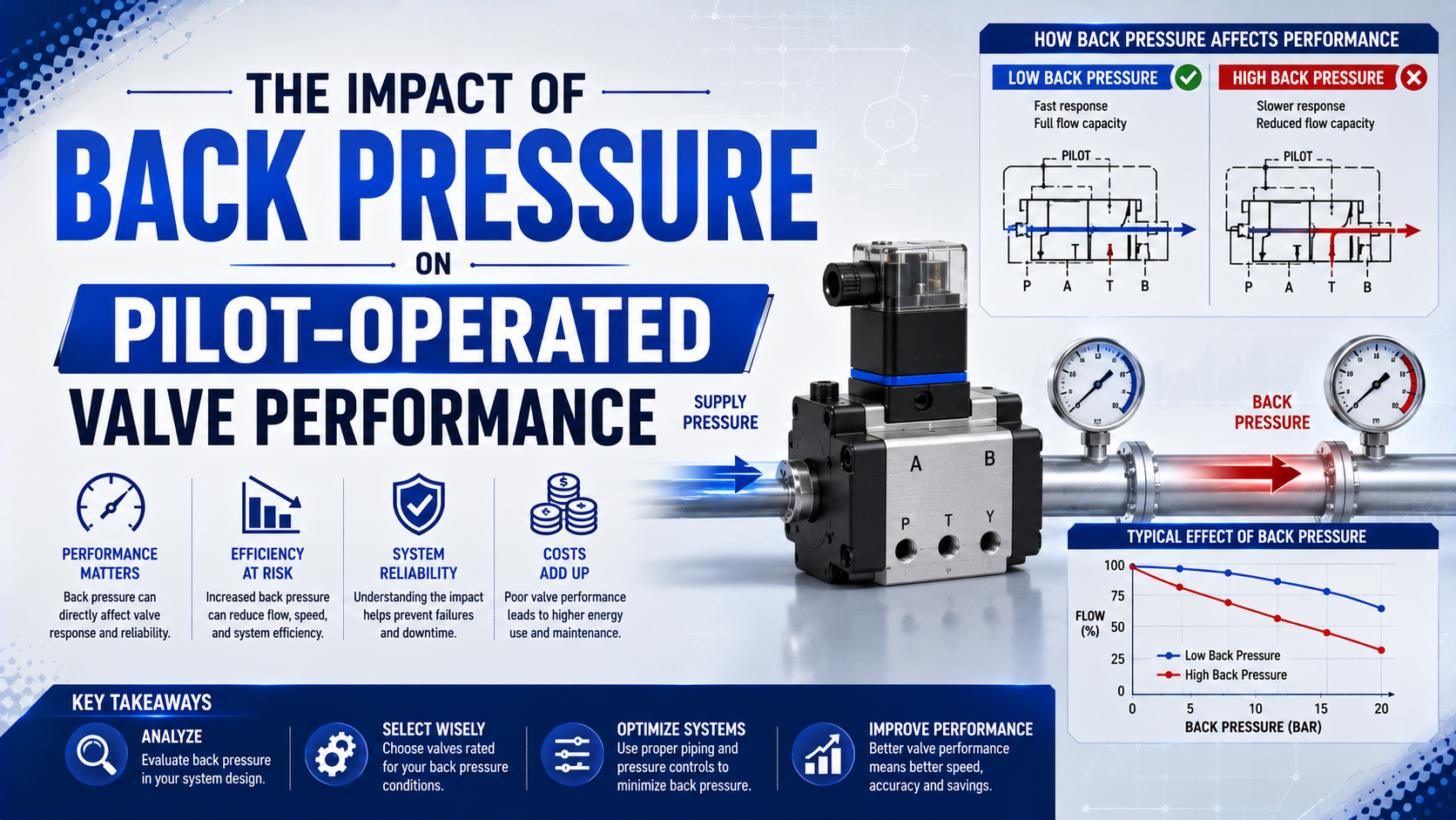
Back pressure can delay, prevent, or reverse the intended movement of a pilot-operated valve when it reduces the pressure difference that moves the pilot or main element. The effect depends on the valve architecture and the port where pressure accumulates. A universal percentage of supply pressure cannot describe every valve.
SMC’s SYJ documentation illustrates the point. One externally piloted family permits main pressure from -100 kPa to 0.7 MPa while requiring 0.15-0.7 MPa at the external pilot port. Main-line pressure and pilot pressure are separate acceptance limits, not one ratio (SMC SYJ300/500/700 manual, accessed 2026).
Key Takeaways
- One SMC SYJ family requires 0.15-0.7 MPa external pilot pressure.
- Identify whether pressure is at the main outlet, common exhaust, pilot exhaust, or opposing pilot chamber.
- Compare dynamic readings with the exact valve datasheet.
- Never treat 60% or 80% of supply as a universal failure threshold.
This guide focuses on the narrow valve-level question: how back pressure changes pilot force, spool transfer, and manifold interaction. For plant and actuator exhaust restrictions, start with the general pneumatic back-pressure guide. For two-stage valve construction, use the pilot-operated valve working-principle guide.
Here, pilot-operated valve means a solenoid- or air-piloted directional valve or process valve with a separate control stage. A pilot-operated check valve uses pilot pressure to release a load-holding check element and has a different failure boundary.
Pressure Boundaries Inside a Pilot-Operated Valve
ASCO defines the minimum operating pressure differential for 3-way and 4-way pilot valves between the pressure and exhaust ports, and says it must be maintained through the operating cycle for complete transfer. That definition separates the useful pressure difference from the valve’s maximum working pressure (ASCO Engineering Information, accessed 2026).
Start by labeling the pressure boundary that is actually causing trouble. The word back pressure may describe any of four different conditions:
| Pressure location | Typical port or passage | What the pressure opposes |
|---|---|---|
| Main outlet pressure | Outlet of a 2/2 process valve | Inlet-to-outlet differential that opens or holds the main element |
| Main exhaust pressure | Ports 3 and 5 on a directional valve | Cylinder exhaust flow and sometimes the internal pilot exhaust |
| Pilot exhaust pressure | PE, 82/84, or a dedicated pilot vent | Discharge from the pilot piston, diaphragm, or spool end |
| Opposing pilot pressure | Port 12 or 14 on a double-piloted valve | The commanded pilot force on the opposite end |
Which pressure changed first?
The same gauge value can produce different results at those four locations. Outlet pressure on a floating-diaphragm valve reduces the main-stage differential. Pressure in a directional-valve exhaust gallery may slow cylinder discharge. It can also act on the pilot circuit or push air into another station. Pressure at an isolated pilot vent acts much closer to the valve’s switching mechanism.
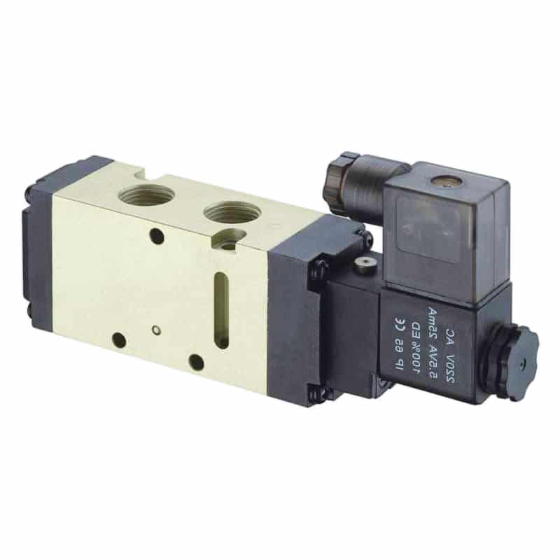
A solenoid-piloted directional valve contains a small control stage and a larger main flow stage. Diagnose their pressure paths separately.
A meaningful test result therefore needs two names, not one: the pressure measurement point and the output being observed. “0.08 MPa at pilot exhaust when the spool fails to complete its stroke” is actionable. “Back pressure is 20%” is not, because it hides the reference pressure, valve state, and affected stage.
Why Can Back Pressure Slow or Prevent Switching?
ASCO’s Series 316 instructions require a minimum differential between pressure and exhaust and specify that both pipes remain full-area and unrestricted. That manufacturer warning explains the mechanism: rising exhaust pressure reduces the force margin that accelerates the moving valve element (ASCO Series 316 instructions, 2017).
A simplified force balance is useful as long as the valve’s actual pressure areas are known:
is the net force available to move the pilot piston, diaphragm, or spool. Pressures and must use the same reference and are measured in pascals. Areas and are in square metres, while spring and friction forces are in newtons.
Back pressure raises or reduces the available differential across the main stage. Once the force margin falls, several outcomes are possible:
- Longer delay: the element waits for enough pressure imbalance to overcome spring preload and static friction.
- Partial transfer: the spool moves but does not reach the full-flow position. The actuator then appears slow even though the coil is energized, and the restriction may be mistaken for a downstream flow-control setting.
- Failure to reset: trapped pilot pressure opposes the return mechanism.
- Chatter or repeated transfer: pressure pulses repeatedly cross the shift threshold and make the element move back and forth.
- Cross-actuation: a common exhaust gallery sends a pressure pulse into another valve or actuator circuit.
Response time cannot be predicted from back pressure alone. ASCO’s engineering guide says response also depends on valve size, operating mode, electrical service, medium, temperature, inlet pressure, and pressure drop. That is why a valve can pass a static bench test yet miss timing on the machine.
The force model is a diagnostic map, not a substitute for the manufacturer’s internal areas. If those areas are unpublished, measure the external pressures, coil current, spool feedback when available, and final port response instead of inventing an area ratio.
Why Is There No Universal Safe Back-Pressure Percentage?
Parker’s isys H service data lists internal-pilot minimum pressures from 173 to 345 kPa depending on valve size and function, while its external-pilot range is 310-1,000 kPa. Those model-specific values disprove a universal 60% or 80% supply-pressure limit (Parker isys H, accessed 2026).
The allowable outlet or exhaust pressure depends on at least five design variables:
- the main element type: spool, diaphragm, piston, or poppet;
- the pressure-responsive areas on both sides of that element, including any area that changes as the element moves through its stroke;
- whether the pilot air is internal, external, or remote;
- whether pilot and main exhaust are common or separated in the valve and manifold;
- spring force, seal friction, centre condition, and the required final position.
Festo shows the same model dependency in its VUVS documentation. Depending on the valve function, internal-pilot operating pressure begins at 1.5 or 2.5 bar, and the external-pilot version allows a main operating range down to -0.9 bar while retaining a positive pilot-pressure requirement (Festo VUVS/VTUS, 2026).
What percentage should an engineer use, then? None unless the manufacturer explicitly defines one for that valve and condition. Use the stated minimum pilot pressure, minimum operating differential, allowable outlet pressure, pilot-exhaust requirement, and flow characteristic. If the datasheet omits an outlet-back-pressure limit, obtain written confirmation or test the exact assembly under the intended conditions.
A percentage without a boundary is unusable.
Do not transfer an exhaust-cleaner limit to the valve. For example, an older SMC AMC exhaust-cleaner catalog specifies operation at 0.1 MPa back pressure or less for that accessory. It does not establish 0.1 MPa as a universal limit for every upstream valve (SMC AN/AMC catalog, accessed 2026).
How Do Internal and External Pilot Circuits Behave Differently?
Festo’s VUVG documentation gives internal-pilot ranges of 1.5-8, 2.5-8, or 3-8 bar depending on the valve, while external pilot air enters through port 12/14. It also identifies pilot exhaust through vent holes or manifold duct 82/84 (Festo VUVG/VTUG, 2019).
An internal-pilot valve takes its control air from the main supply. Installation is compact, but the pilot force follows supply pressure. A fast actuator or undersized supply path can pull port 1 below the pilot minimum. The same can happen when a soft-start valve or shared demand creates a transient drop during the exact part of the cycle when the spool must transfer. An external-pilot valve, by contrast, receives control pressure from a separate port. It can operate a main circuit at low pressure or vacuum only if the separate pilot supply and pilot exhaust are connected correctly. External pilot does not make the valve immune to back pressure; it moves the control boundary to dedicated ports.
SMC makes that distinction explicit. Its SYJ external-pilot examples allow main pressure from -100 kPa to 0.7 MPa, while the external pilot remains within 0.15-0.7 MPa. The main circuit can therefore cross vacuum and positive pressure without using that main pressure as the pilot source.
| Architecture | Supply dependency | Exhaust risk | Best diagnostic measurement |
|---|---|---|---|
| Internal pilot, common exhaust | Pilot force follows port 1 | Main exhaust can disturb pilot discharge | Port 1 plus ports 3/5 during transfer |
| Internal pilot, separate pilot exhaust | Pilot force follows port 1 | Dedicated vent can still clog | Port 1 plus PE or 82/84 |
| External pilot, common exhaust | Pilot supply is independent | Main exhaust may still affect pilot return | Pilot port, ports 3/5, and spool response |
| External pilot, separate exhaust | Control paths are most isolated | Incorrect PE piping or pressure pulses remain possible | Pilot supply and pilot exhaust together |
The port map decides the test.
Never assume port numbering from appearance. Confirm the pneumatic symbol, manifold plate, ordering code, and manual. A plug installed in the wrong PE or 82/84 connection can turn a stable external-pilot design into an intermittent fault.
When Does Manifold Exhaust Back Pressure Cause Cross-Actuation?
SMC states that its SY pilot valve and main valve share a common internal exhaust and instructs users not to block the exhaust port. Its current SY catalog also says a back-pressure check valve prevents actuator and air-operated valve malfunctions caused by exhaust from other valves (SMC SY manual, accessed 2026).
A shared manifold is most vulnerable when several large chambers exhaust together. Their combined transient flow raises pressure in ducts 3 and 5. That pulse can reach a pilot exhaust passage, leak across a valve interface, or push into the working port of an uncommanded valve. The result may look electrical because another axis moves when a solenoid changes state. Festo’s 2026 VTUS documentation recommends exhaust-pressure separation when exhaust pressures are high and requires at least one supply plate for each pressure zone. It also notes that pressure-zone separation is not available in pilot-air ducts 12 and 14, so the manifold architecture must be read before separators are specified (Festo VUVS/VTUS, 2026).
One valve operating alone may appear healthy. The fault emerges only when another station exhausts. That pattern is a strong reason to log simultaneous valve commands and manifold pressure rather than replacing the first solenoid that appears late.
Where Should You Measure Pressure During a Fault?
ISO 6358-1 defines steady-state tests for pneumatic components with compressible flow, while its 2026 Amendment 2 addresses measurement uncertainty. Machine switching is transient, so catalog flow data should be combined with synchronized pressure and command traces rather than treated as a complete dynamic test (ISO 6358-1, 2013; Amendment 2, 2026).
Use sensors with sufficient pressure range and bandwidth, then put every channel on one clock. The minimum useful set is:
- the electrical command at the valve connector;
- actual coil voltage or current, measured during the reported fault rather than inferred from the indicator LED;
- port 1 pressure at the valve;
- external pilot pressure at port 12 or 14 when used;
- pilot exhaust pressure at PE or 82/84, preferably at the valve or manifold rather than at the end of a long tube;
- main exhaust pressure at ports 3 and 5 or the manifold exhaust outlet;
- a response signal such as spool feedback, working-port pressure, flow, or actuator motion.
Mount the pressure tap close to the valve. A gauge at the compressor room cannot show a 60 ms pressure collapse at a manifold. Likewise, a slow mechanical gauge can hide a short exhaust pulse that cross-actuates another station. State the sensor range, sample rate, tap volume, tube length, and filter settings in the test record. In our experience, four aligned traces answer the question fastest: coil current, pilot pressure, exhaust pressure, and spool or actuator position. A healthy current trace with collapsing pilot pressure points to the pneumatic control path. Stable pilot pressure with delayed spool motion points toward friction, contamination, or damage inside the valve.
One sensor is rarely enough.
Perform the test at the condition that causes the complaint. Include the lowest expected supply pressure and maximum simultaneous exhaust demand. Keep the normal operating temperature, installed silencer, and actual cycle rate. A disconnected bench valve does not reproduce a shared exhaust manifold.
A Diagnostic Sequence for Sluggish or Intermittent Switching
SMC requires the external-pilot PE connection on one SY manifold family to remain vented to atmosphere and free from pressure pulses from other devices. That single instruction provides a useful diagnostic priority: verify pilot exhaust before changing coils, timers, or PLC logic (SMC SY installation manual, accessed 2026).
Follow the pressure path from command to output:
- Confirm the exact valve code. Identify the function and pilot option first. Then record the return method, centre state, manifold plate, and every dedicated pilot-exhaust port shown for that ordering code.
- Verify the electrical command. Measure voltage and current at the coil during the fault. An LED proves a command, not adequate coil force.
- Check dynamic supply pressure. Compare port 1 with the manufacturer’s minimum internal-pilot pressure during the fastest demand event.
- Measure the pilot drive. For an external-pilot valve, verify port 12 or 14 while the main circuit is loaded.
- Measure pilot exhaust. Check PE or 82/84 for a blocked tube or fitting. Also inspect any silencer, check valve, and shared pressure path connected to that vent.
- Measure main exhaust. Compare individual and simultaneous valve operation. A spike that appears only during another station’s exhaust is evidence of manifold interaction, especially when the valve response changes on the same time base.
- Isolate restrictions one at a time. Test the silencer, remote exhaust tube, manifold outlet, and flow control using a safe temporary configuration.
- Inspect the valve last. Exclude external pressure faults before attributing the symptom to internal contamination, seal swelling, spool damage, or a weak spring.
For coil, connector, spool, contamination, and leakage checks beyond the pressure path, use the solenoid-valve troubleshooting guide. If pressure remains after the command changes, compare the findings with the silencer-clogging guide.
Do not bypass safeguards to reproduce a fault. ISO 4414:2010 covers safety requirements for pneumatic systems and their components, including installation, adjustment, maintenance, and reliable operation. Apply the machine’s isolation, residual-energy, and restart procedures before opening any exhaust path (ISO 4414, confirmed current in 2021).
How Should Exhaust Restrictions Be Corrected?
SMC advises selecting a silencer with a larger effective area than the solenoid valve and replacing it when clogging reduces exhaust speed and system performance. That is a component-specific sizing rule, not a promise that every larger silencer will solve the circuit (SMC AN silencer catalog, accessed 2026).
Fix the boundary that failed.
Correct the measured restriction without removing intentional machine control:
| Finding | Preferred correction | Verification |
|---|---|---|
| Clogged silencer | Replace with a compatible unit sized for valve exhaust flow | Compare exhaust pressure and cycle time before and after |
| Long or undersized remote exhaust | Increase internal diameter, shorten routing, or add an approved exhaust plate | Test maximum simultaneous flow |
| Shared manifold pulse | Add supply/exhaust plates, separate pressure zones, or use specified check valves | Repeat the cross-actuation test |
| Blocked pilot exhaust | Restore PE or 82/84 routing exactly as documented | Confirm near-atmospheric discharge without foreign pulses |
| Internal-pilot pressure collapse | Improve supply conductance or select external pilot where permitted | Verify pilot pressure at minimum plant pressure |
| Excess downstream pressure on a process valve | Reduce outlet restriction or select a valve rated for the required differential | Check the full operating envelope |
A quick exhaust valve is not a universal cure. It can reduce the actuator’s exhaust path, but it may bypass meter-out speed control or change stopping behaviour. It may also create a new noise or contamination exposure while leaving the pilot exhaust problem untouched. Review the quick-exhaust valve physics guide before adding one. The correct fix follows the pressure boundary. If PE pressure causes the missed shift, increasing the main exhaust tube may do nothing. If ports 3 and 5 see a shared transient, replacing the coil may do nothing. Change one boundary, repeat the same loaded test, and retain the before-and-after traces.
Avoid raising plant pressure as a shortcut. Higher supply can temporarily increase pilot force. It also increases exhaust mass and energy use, potentially making the next pressure pulse larger. The related pressure-drop troubleshooting guide explains why the largest restriction should be found instead.
Selection and Commissioning Requirements
Festo’s 2026 VTUS catalog allows up to 16 valve positions in one configuration and recommends a separator when exhaust pressures are high. More stations do not automatically mean a problem, but simultaneous-flow cases must be defined before the manifold and exhaust zones are ordered (Festo VUVS/VTUS, 2026).
Specify the control and flow paths separately:
- full manufacturer and valve order code;
- valve function and flow direction;
- internal or external pilot supply and its permitted pressure range;
- pilot ports 12/14 and pilot exhaust ports PE or 82/84, including how those passages are routed through the selected manifold plate;
- minimum operating differential and maximum outlet or exhaust pressure for every intended valve state;
- port 1, working-port, and exhaust-port flow characteristics;
- manifold station count, centre conditions, return methods, and simultaneous valve operation;
- pressure zones, supply plates, exhaust plates, check valves, and silencers;
- tube size and length;
- fittings and remote exhaust routing, including any reduction near a silencer or exhaust collector;
- medium, filtration class, temperature, duty cycle, and installation orientation;
- required switching time and the method used to measure it;
- safe state during loss of electrical power, supply pressure, or pilot pressure.
Commissioning should include individual and simultaneous operation. Record the lowest supply condition, worst actuator load, highest exhaust demand, cold start, thermal equilibrium, and fault recovery. A valve that shifts correctly ten times on an unloaded bench has not passed a production acceptance test. Use ISO 6358 data to compare steady-state conductance, but keep dynamic acceptance separate. The standard excludes cylinders and components with unstable flow coefficients from its Part 1 method. For actuator force consequences, use the cylinder back-pressure force-loss guide rather than extending valve data to the load without measurement. Your RFQ should ask the supplier to identify every percentage reference. Is it based on supply pressure, operating differential, pilot pressure, or a rated span? If the answer is unclear, the percentage cannot protect the application.
Pilot-Operated Valve Back Pressure FAQs: What Should Engineers Ask?
Parker’s isys H data spans 173-345 kPa minimum internal-pilot pressure across listed functions and sizes, while Festo publishes other product-specific ranges. These five answers keep diagnosis tied to the selected valve instead of a universal back-pressure percentage (Parker; Festo, accessed 2026).
What back-pressure percentage makes a pilot-operated valve fail?
There is no universal percentage. Parker lists different internal-pilot minimums from 173 to 345 kPa for isys H functions, while SMC and Festo publish other ranges. Use the exact minimum differential, pilot-pressure range, outlet limit, and exhaust instructions for the complete valve code under dynamic load (Parker, accessed 2026).
Can external pilot air eliminate back-pressure problems?
No. SMC’s SYJ examples still require 0.15-0.7 MPa external pilot pressure, and the pilot exhaust must vent correctly. Another SMC manual requires the PE connection to remain at atmosphere without pressure pulses. Main exhaust can also restrict actuator flow or interact with other manifold stations (SMC, accessed 2026).
Why does the valve fail only when another cylinder moves?
Simultaneous exhaust can raise pressure in shared manifold ducts. Festo’s 2026 VTUS catalog allows up to 16 valve positions and recommends separating zones when exhaust pressures are high. Log commands and pressure at ports 3 and 5 while both cylinders cycle to confirm the interaction (Festo, 2026).
Should a silencer be removed to test the valve?
A controlled temporary test may identify a restriction, but exhaust must remain safe. SMC specifies a 0.1 MPa maximum for one AMC exhaust-cleaner application and says clogged silencers should be replaced. That accessory limit is not universal. Restore suitable noise and contamination control after testing (SMC, accessed 2026).
Which pressures should be included in a valve acceptance test?
Record port 1, external pilot port 12 or 14 when fitted, pilot exhaust PE or 82/84, main exhaust ports 3 and 5, and the controlled output. Compare them with coil current and spool or actuator response at the lowest supply and highest simultaneous exhaust demand (SMC, accessed 2026).
Sources and technical references
- SMC, SY3000/5000/7000 Valve Operation Manual. Retrieved 2026-07-22.
- SMC, SY3000/5000 Installation and Maintenance Manual. Retrieved 2026-07-22.
- SMC, SYJ300/500/700 Installation and Maintenance Manual. Retrieved 2026-07-22.
- SMC, SY Series Web Catalog. Retrieved 2026-07-22.
- SMC, AN Silencers and AMC Exhaust Cleaner Catalog. Retrieved 2026-07-22.
- Festo, Solenoid Valves VUVS and Valve Manifold VTUS, 2026/05. Retrieved 2026-07-22.
- Festo, Solenoid Valves VUVG and Valve Terminals VTUG, 2019/06. Retrieved 2026-07-22.
- Parker, isys H Series Installation and Service Instructions. Retrieved 2026-07-22.
- Emerson ASCO, Series 316 Pilot-Operated Solenoid Valve Instructions, 2017. Retrieved 2026-07-22.
- Emerson ASCO, Engineering Information for Solenoid Valves. Retrieved 2026-07-22.
- ISO 6358-1, Steady-State Flow-Rate Characteristics of Pneumatic Components, 2013. Retrieved 2026-07-22.
- ISO 6358-1:2013/Amd 2, Evaluation of Measurement Uncertainty, 2026. Retrieved 2026-07-22.
- ISO 4414, Pneumatic Fluid Power Safety Requirements, 2010. Retrieved 2026-07-22.