

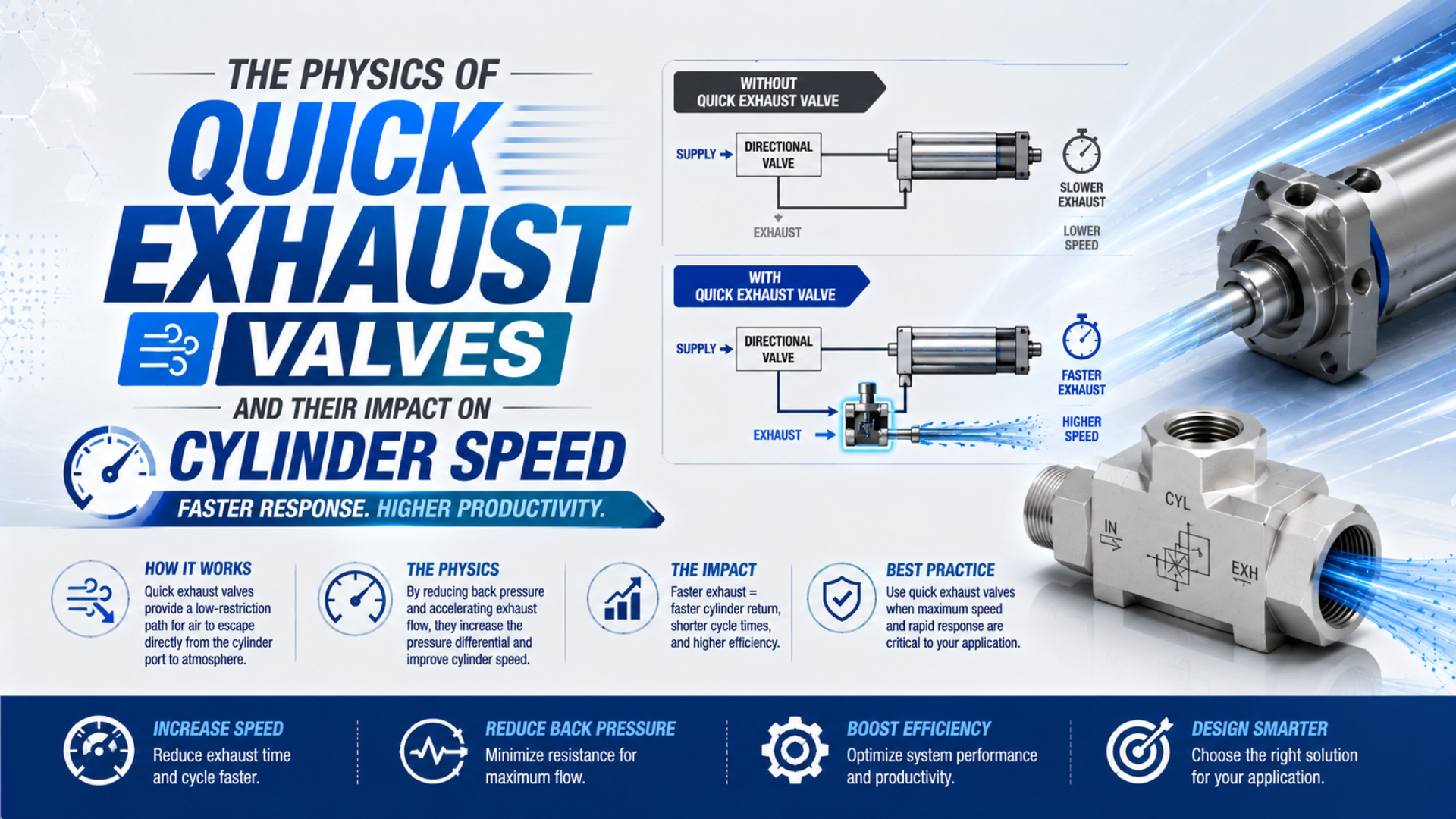
A quick exhaust valve is a self-actuating 3-port pneumatic component that changes cylinder speed by changing the exhaust boundary condition. Instead of forcing chamber air through a long tube and the directional valve, it opens a local path to atmosphere. Exhaust pressure can then fall sooner, reducing the force that opposes piston motion. The result is application-specific, not a universal percentage gain.
Festo’s current SE/SEU data illustrates the scale and the limits. Its listed supply-flow values range from 300 to 4,560 L/min, while exhaust ratings depend on model and test pressure. The valve can remove one bottleneck, but cylinder speed still depends on the complete supply path, exhaust path, load, friction, and cushioning (Festo SE/SEU, 2025).
Key Takeaways
- A quick exhaust valve uses 3 ports to vent one cylinder chamber locally.
- Early discharge can be choked, but it becomes subsonic as chamber pressure falls.
- Lower exhaust pressure changes piston net force and acceleration.
- Validate improvement with repeated stroke-time and dynamic-pressure measurements, not a fixed percentage (Festo; RWTH, 2025).
This guide focuses on the transient physics and the measurements that prove a result. For general construction, installation, and product selection, start with how a quick exhaust valve works. For an intentionally fast stroke and controlled return stroke, use the separate differential-speed circuit guide.
What Does a Quick Exhaust Valve Physically Change?
Festo describes a 3-port sequence: air flows from port 1 to port 2 while exhaust port 3 is closed; when pressure at port 1 falls, the cylinder side vents from port 2 to port 3. Mounting at the cylinder removes most of the remote return path (Festo, 2025).
The directional valve still decides which chamber receives supply and which line is released. The quick exhaust valve does not add a second power source. Its internal diaphragm, poppet, or seal responds to the pressure difference between the control-valve side and cylinder side.
During filling, upstream pressure pushes the element against the exhaust seat. During reversal, upstream pressure falls. Higher cylinder-side pressure shifts the element, blocks the return connection, and opens the local atmospheric exhaust.
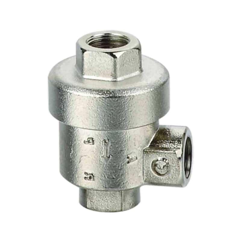
The external body shows three flow connections, but the model datasheet remains the authority for port identity, permitted pressure, and flow direction.
The valve changes where the chamber pressure is allowed to decay. That is more precise than saying it “adds speed.” If the remote directional valve and tubing were already nonrestrictive, the pressure trace may barely change. If they were the dominant exhaust restriction, local venting can change both the delay before motion and the acceleration during travel.
How Does Pressure Difference Switch the Valve?
SMC identifies 3 conditions that can cause insufficient exhaust or vibration in its ASV speed-exhaust family: residual inlet pressure, differential pressure below the minimum operating value, and an inlet-side effective area smaller than the ASV path. Switching therefore depends on pressure history, not merely port size (SMC ASV).
At reversal, the directional valve must release pressure on the quick exhaust inlet quickly enough for cylinder-side pressure to move the internal element. A long or restricted inlet line can keep that side pressurized. The quick exhaust valve may open late, oscillate, or fail to establish the intended local path.
The sequence has four observable stages:
- Supply: pressure at the inlet closes the atmospheric seat and fills the chamber.
- Command reversal: the directional valve connects the inlet line to its exhaust gallery.
- Pressure crossover: cylinder-side pressure exceeds inlet-side pressure by the valve’s effective switching requirement.
- Local exhaust: the internal element closes the inlet path and exposes the cylinder chamber to the local exhaust outlet.
Do not assume “zero delay.” The directional valve has a switching time, the line has volume, the inlet pressure must decay, and the quick exhaust element must travel. SMC’s warning about insufficient differential pressure is why a static regulator gauge cannot prove correct switching.
Quick Exhaust Is a Transient Blowdown Event
NASA shows that maximum mass flow occurs when gas reaches Mach 1 at the smallest effective area. A pneumatic chamber initially discharging to atmosphere can meet that choked condition, but its upstream pressure falls continuously. The event therefore moves from an early flow-limited phase toward subsonic discharge (NASA Glenn).
For an ideal gas through an ideal converging restriction, a useful screening relationship is:
Here, is downstream absolute pressure, is upstream absolute pressure, and is the gas specific-heat ratio. Using for air gives an ideal critical ratio near 0.528. Gauge pressure must not be used in this ratio.
This equation is a physics screen, not a valve rating. Real quick exhaust valves contain bends, seals, finite poppet travel, silencers, and non-ideal passages. ISO 6358 uses tested compressible-flow characteristics for components rather than treating every device as an ideal nozzle (ISO 6358-1).
What happens after the chamber pressure falls? The critical condition ends, mass flow becomes sensitive to both upstream and downstream pressure, and the remaining exhaust tail can dominate positioning or sensor timing. A large peak exhaust rating does not guarantee a short complete pressure-decay time.
Back Pressure Changes the Piston Force Balance
A 2025 RWTH study compared 18 load cases and found that lower back pressure with a switchable quick-exhaust arrangement produced higher acceleration and maximum velocity in its tested system. One reported case reduced cycle time from 0.94 to 0.78 seconds, but those values belong to that experiment (RWTH Aachen, 2025).
The piston accelerates according to net force, not supply pressure alone:
is net accelerating force. is the driving pressure-area term, is the opposing exhaust-side term, is external load force, and represents seal, guide, and mechanism friction. Use chamber gauge pressures referenced to the same ambient pressure. If you use absolute pressures, include the external atmospheric force and the applicable piston and rod areas explicitly.
A quick exhaust valve can reduce sooner. That increases the pressure-force difference without increasing regulator pressure or cylinder bore. The effect can appear as shorter motion delay, higher initial acceleration, greater peak velocity, or some combination of the three.
This is why a speed percentage transfers poorly between machines. The same reduction in exhaust pressure creates different acceleration when piston areas, loads, friction, and cushion settings differ. The right comparison is the pressure trace aligned with piston position or time, not a before-and-after stopwatch alone.
For a detailed treatment of the opposing pressure term, see how back pressure affects pneumatic equipment.
How Does Required Chamber Flow Relate to Speed?
SMC gives the first-pass imperial relationship , where speed is in inches per second, flow is in SCFM, and piston area is in square inches. SMC explicitly holds inlet pressure constant and notes that ports and tubing also affect speed (SMC).
Written as a screening equation:
is piston speed in inches per second, is airflow in SCFM on the stated reference basis, and is effective piston area in square inches. The relationship is useful for translating a target speed into a flow scale. It is not a transient quick-exhaust simulation.
Why isn’t the result a guarantee? Flow changes during the stroke, chamber pressure is not constant, and the cylinder must accelerate before reaching its travel velocity. Directional-valve response, tube volume, quick-exhaust switching, load, seal friction, cushion entry, and sensor logic all consume time outside the simple relationship.
Use the calculated demand as a comparison point. Then compare manufacturer-tested exhaust data, fittings, silencers, cylinder ports, and the actual pressure trace. If you already know the pneumatic line volume, the Tube Volume Calculator can quantify the trapped volume between the cylinder and the local valve.
Why Does Mounting Distance Affect the Result?
The 2025 RWTH experiment recorded 55 cycles while studying pneumatic line lengths of 1, 4, and 6 m, using extra sensors on both sides of its quick-exhaust spool. Festo likewise instructs users to mount its valve directly on the cylinder connection for full and quick exhausting (RWTH; Festo).
Every tube segment between the cylinder and quick exhaust valve becomes volume that must change pressure with the chamber. Moving the valve away from the actuator leaves more compressed air upstream of the local exhaust seat. That can delay pressure crossover, increase the mass that must discharge, and soften the advantage over the remote directional-valve path.
Distance is not the only geometric variable. Tube inside diameter, elbows, push-in fittings, cylinder-port passages, and an attached silencer all contribute effective conductance and dead volume. A short tube with a very small bore can still dominate the event.
For a cylindrical tube, internal volume is:
is tube volume, is actual inside diameter, and is length between the chamber and quick exhaust valve. Use consistent units. The equation quantifies stored volume, but it does not calculate switching time or compressible mass flow by itself.
The broader relationship between connection geometry and chamber timing is covered in port geometry and cylinder fill/exhaust time.
What Do Catalog Flow Ratings Actually Prove?
ISO 6358-1 remains current after a 2022 confirmation and now has a 2026 measurement-uncertainty amendment. It defines steady-state compressible-flow testing for pneumatic components. It does not test a complete moving cylinder or directly predict transient stroke time (ISO 6358-1; 2026 amendment).
Festo’s 2025 SEU table shows why direction and test pressure matter. Its G1/4 model lists 1,100 L/min exhaust flow from 6 to 5 bar, 2,300 L/min from 6 bar to atmosphere, and 960 L/min in the supply direction. Those are three different paths or pressure conditions, not conflicting values.
Compare the correct data in this order:
| Data item | What it answers | What it does not answer |
|---|---|---|
| Port thread | Can the hardware connect mechanically? | Internal area or mass flow |
| Nominal flow under stated pressures | How this tested path compares at one standard condition | Complete pressure-decay time |
| Sonic conductance and critical pressure ratio | How a component behaves across compressible-flow regions | Cylinder motion under load |
| Exhaust-to-atmosphere flow | Capacity for the stated inlet and outlet condition | Noise, cushion demand, or switching delay |
| Machine pressure trace | What happened in the installed circuit | Performance at every future condition |
Don’t compare an exhaust-to-atmosphere value with a 6-to-5 bar rating as if they share the same pressure basis. Record direction, upstream pressure, downstream pressure, temperature/reference basis, and whether the silencer is included. The Cv Calculator can support a catalog comparison, but manufacturer pneumatic data remains primary.
Faster Motion Moves the Limit to Cushioning and Noise
Festo lists sound-pressure values from 83 to 95 dB(A) across four cited SEU sizes, while the 2025 RWTH test tuned each system for minimum movement time without overloading the pneumatic end cushion. A faster exhaust path therefore moves attention from flow restriction to stopping energy and local noise (Festo; RWTH).
Kinetic energy rises with the square of velocity. If velocity increases by a factor of , the ideal kinetic-energy ratio is for the same moving mass. That relationship does not predict the achieved velocity, but it explains why a modest speed increase can demand a larger cushion or shock-absorber margin.
Check these consequences before approving the change:
- end-cushion entry velocity and adjustment range;
- external shock-absorber capacity and remaining stroke;
- cylinder mounting, guide, tooling, and frame reaction loads;
- sensor timing, PLC windows, dwell, rebound, and repeatability;
- exhaust sound at a defined distance and operating condition;
- oil mist, condensate, particles, icing, or contamination at the local vent;
- silencer restriction when new and after realistic service exposure.
A quick exhaust valve and meter-out controller solve different problems. Meter-out control intentionally preserves exhaust resistance for stable motion; local exhaust removes resistance. Review meter-in versus meter-out control when the load can overrun, and use the cylinder cushioning guide before accepting a higher impact speed.
Rapid expansion can also cool the remaining gas and valve body. Cooling does not automatically “increase flow.” It changes gas state and may encourage condensate or icing when moisture is present. The separate guide to adiabatic expansion in cylinders covers that boundary.
How Should You Prove the Speed Improvement?
The 2025 RWTH study recorded 55 cycles per load case, discarded the first 3 and last 2, and evaluated 18 load cases at 7 bar absolute with a 1 m, 4 mm-ID line. That method shows why a repeatable baseline is stronger than one favorable stopwatch result (RWTH Aachen).
Measure the baseline and candidate under the same load, supply condition, flow-control setting, cushion setting, temperature state, and command logic:
- Record both stroke times separately. A valve at one chamber normally targets one direction.
- Measure dynamic supply pressure. Supply collapse can imitate an exhaust problem.
- Measure both chamber pressures. Align the traces with command time and piston position.
- Measure across the quick exhaust inlet and cylinder port. Confirm when pressure crossover and switching occur.
- Record velocity or position. Separate command delay, acceleration, travel, and cushion deceleration.
- Repeat enough cycles. Stabilize temperature and reject only cycles under a documented rule.
- Run the worst credible condition. Include maximum payload, minimum permitted supply pressure, sustained cycle rate, and simultaneous consumers.
- Check noise and the outlet environment. Measure with the final silencer or exhaust duct installed.
In our experience, the most informative plot overlays the exhausting-chamber pressure and piston position. A sharp pressure drop before acceleration supports the intended local-exhaust effect. A slow decay points toward inlet pressure, valve switching, port geometry, silencer restriction, or another downstream bottleneck. A fast decay without faster motion redirects the investigation toward load, friction, supply, or cushioning.
Do not remove the silencer and leave the outlet open as a permanent “fix.” A temporary comparison requires an approved procedure that controls noise, expelled particles, and the air jet. The pneumatic silencer engineering guide explains why sound data and flow data must be evaluated together.
What Should a Quick Exhaust Valve Specification Include?
Festo’s 2025 unsilenced SE range spans G1/8 to G3/4 connections and model-specific exhaust values from 660 to 7,500 L/min at 6-to-5 bar conditions. SMC separately warns that one ASV model may not increase cylinder speed when its sonic conductance is below the paired speed controller’s value (Festo; SMC).
An RFQ should identify the operating point, not merely the thread:
- directional-valve manufacturer, model, function, and exhaust data;
- cylinder type, bore, rod diameter, stroke, port thread, and cushion type;
- target direction, current stroke time, target stroke time, and payload;
- working pressure range and measured dynamic pressure at the machine;
- tube OD, actual ID, length, fittings, and valve-to-cylinder distance;
- quick exhaust supply and exhaust ratings with their test conditions;
- minimum switching pressure or differential-pressure requirement;
- exhaust silencer or duct model and its flow data;
- ambient temperature, air quality, lubrication, moisture, and contamination;
- allowable sound level, stopping-energy limit, sensor window, and cycle rate.
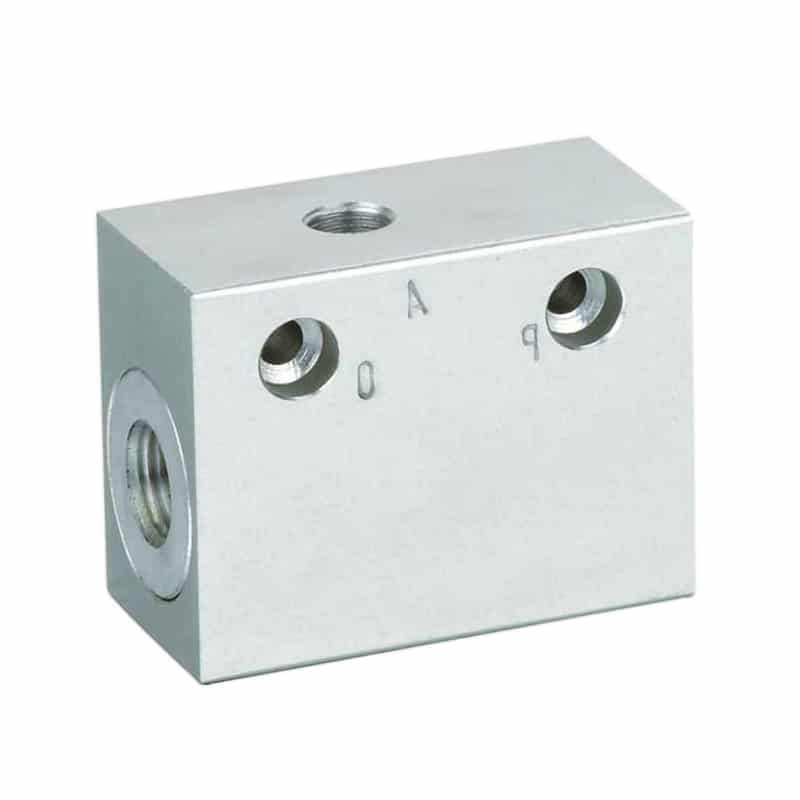
Block-style and inline bodies can expose different port layouts. Connect by the selected model’s symbol and markings, not by appearance.
Do you need one valve or two? Follow the chamber that exhausts during the stroke you want to change. A conventional double-acting cylinder may need one valve for one fast direction or two independently reviewed valves for both directions. The detailed placement logic belongs in the differential-speed circuit article.
For application review, send the circuit, valve models, bore, stroke, line dimensions, dynamic pressure traces, payload, and target timing through the technical contact page.
Quick Exhaust Valve Physics FAQs: What Should Engineers Ask?
Festo publishes 3 functional ports and up to 7,500 L/min in one model-specific 6-to-5 bar exhaust table, while SMC lists 3 conditions that can prevent reliable local exhaust. These five answers keep speed, switching, flow, and safety conclusions tied to the selected circuit rather than one universal gain (Festo; SMC).
Does a quick exhaust valve guarantee a fixed cylinder-speed increase?
No. The 2025 RWTH experiment reduced one reported cycle from 0.94 to 0.78 seconds, but that result came from a defined cylinder, load, pressure, line, and control strategy. Your gain depends on whether the remote exhaust path was the limiting restriction and must be measured under the real machine conditions (RWTH).
Is quick-exhaust flow choked during the entire stroke?
Usually not. NASA identifies Mach 1 at the smallest effective area as the choked limit. As cylinder pressure falls, the downstream-to-upstream pressure ratio rises and the discharge transitions toward subsonic flow. The switching passage, silencer, and actual component characteristics also prevent an ideal-nozzle equation from describing the entire event (NASA Glenn).
Why can a quick exhaust valve chatter or fail to open fully?
SMC identifies 3 relevant conditions: residual or back pressure at the inlet, differential pressure below the valve’s minimum operating requirement, and an inlet-side effective area smaller than the exhaust controller. Measure pressure on both sides during reversal, then inspect the directional-valve exhaust, tubing, fittings, orientation, and silencer (SMC ASV).
Can a quick exhaust valve make the cylinder too fast?
Yes. Festo lists 83 to 95 dB(A) for the cited silenced SEU models, and higher piston velocity also raises stopping energy. Recheck cushions, shock absorbers, mounts, guides, tooling, sensors, rebound, noise, and the exhaust environment before accepting the new speed at maximum payload and cycle rate (Festo).
Should I size a quick exhaust valve only by thread size?
No. Festo’s G1/4 SEU example lists 960 L/min supply flow, 1,100 L/min exhaust at 6-to-5 bar, and 2,300 L/min exhaust from 6 bar to atmosphere. The same thread therefore carries several path-specific numbers. Compare direction, pressure basis, sonic conductance, switching requirement, silencer, and measured demand (Festo).
Sources and Technical References
These 7 primary, standards, manufacturer, and research sources support the 3-port sequence, tested flow limits, critical-flow physics, cylinder-speed relationship, switching cautions, and repeated-cycle validation. Model values remain attached to their published pressure and test conditions; none establishes a universal quick-exhaust speed percentage for every pneumatic cylinder (Festo; RWTH).
- Festo, Quick Exhaust Valve SE/SEU, 2025/11.
- SMC, ASV Series Speed Exhaust Controller.
- SMC, Control Air Flow of Cylinders.
- Parker, Quick Exhaust and Shuttle Valve Applications.
- ISO 6358-1:2013, compressible-fluid component flow testing, confirmed 2022 with a 2026 uncertainty amendment.
- NASA Glenn Research Center, Mass Flow Rate Equations.
- Implementation and Experimental Validation of a Time-Controlled Quick-Exhaust for Downstream Throttled Pneumatic Drives, 2025.