

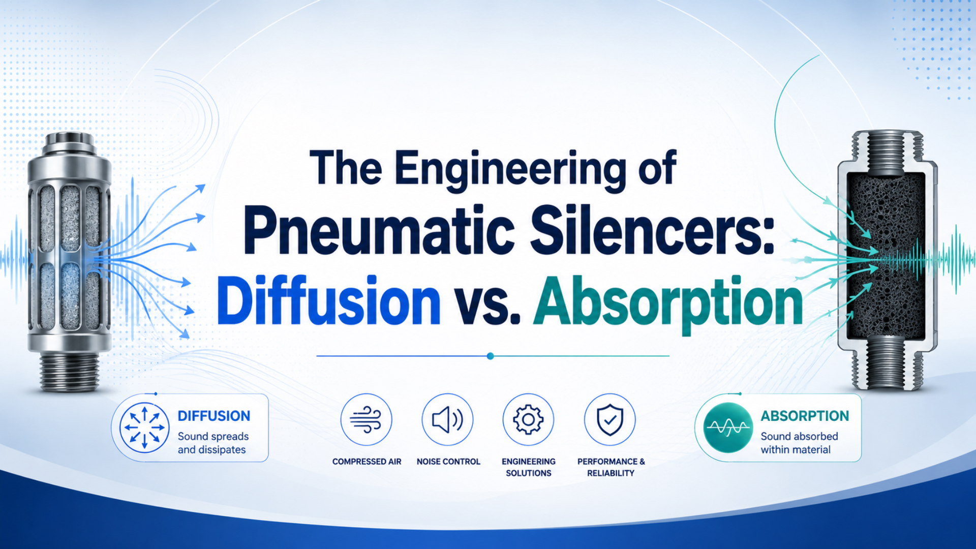
Pneumatic silencer diffusion vs. absorption is not a clean choice between two mutually exclusive product types. A silencer may distribute a concentrated exhaust jet, use expansion spaces or perforated passages to alter pressure waves, dissipate acoustic energy in porous media, or combine these mechanisms. Selection must compare acoustics and exhaust performance under stated test conditions.
Festo, for example, lists one G1/8 UC silencer at 59 dB(A) and 1,700 L/min, with sound measured at 6 bar against atmosphere from 1 m and flow measured at 6 bar upstream (Festo UC). Those numbers are useful because the conditions travel with them. A standalone “quiet” label is not.
Key Takeaways
- One G1/8 Festo UC model is rated at 59 dB(A) and 1,700 L/min at 6 bar.
- Diffusion spreads jets; porous media adds viscous and thermal loss.
- Hybrid designs combine flow distribution, reactive geometry, and dissipation.
- Compare acoustics with flow, exhaust time, and port pressure (Festo UC).
A pneumatic silencer is a component installed at a valve, cylinder, or other pneumatic exhaust port to reduce the sound produced as compressed air discharges to atmosphere. It is also called an exhaust muffler. This article explains the mechanisms and test evidence. For installation, contamination, and general sizing guidance, use the broader pneumatic muffler selection guide.
What Does Pneumatic Silencer Diffusion vs. Absorption Really Mean?
A 2013 study modeled sintered bronze as an equivalent fluid and measured its insertion loss during transient pneumatic exhaust. That single material both redistributes flow through many pores and dissipates acoustic energy. The evidence therefore supports a mechanism-based description, not a strict two-bin taxonomy (Journal of Sound and Vibration).
In practical pneumatic hardware, three mechanisms often overlap:
| Mechanism | What changes inside the silencer | Main engineering consequence |
|---|---|---|
| Diffusive flow distribution | One concentrated jet is divided among many smaller passages or a larger outlet area | Lower local jet velocity and less concentrated discharge |
| Reactive attenuation | Chambers, area changes, perforations, and closed volumes reflect or redirect pressure waves | Frequency-dependent attenuation governed by geometry |
| Dissipative absorption | Viscous shear and heat exchange occur within porous or fibrous media | Acoustic energy is converted to small amounts of heat, with added flow resistance |
“Diffusion” describes what happens to the exhaust path, while “absorption” describes an energy-loss mechanism. They are not opposites at the same taxonomic level. A sintered-metal element can perform both functions, and a chambered design can add reactive attenuation before the air reaches porous media.
Why does that distinction matter on an RFQ? Instead of requesting a “diffusion silencer,” define the port, pressure, exhaust pulse, allowable exhaust time, required acoustic metric, material, and contamination exposure. The supplier can then identify which internal mechanisms satisfy those requirements.
Where Does Pneumatic Exhaust Noise Come From?
The 2013 transient-exhaust study was motivated by high-pressure air released from pneumatic clutch and brake systems, not by a steady fan-like flow. That context matters: rapid valve opening creates a changing pressure ratio, a short high-velocity jet, broadband turbulence, and pressure waves that decay as the chamber empties.
The event begins when a directional valve connects a pressurized actuator chamber to exhaust. If the downstream-to-upstream pressure ratio is low enough, the flow can become choked at the narrowest effective passage. Mass flow then stops increasing in direct proportion to lower downstream pressure. The pneumatic choked-flow guide develops that limit in detail.
Several sources can contribute to the measured sound:
- turbulent mixing between the exhaust jet and surrounding air;
- shock-associated structures during high pressure-ratio discharge;
- pressure pulsation through valve cavities, fittings, and tubing;
- resonance in chambers or piping;
- mechanical impact at the cylinder end cap or machine structure.
A silencer acts primarily on the pneumatic exhaust contribution. What if the measured level barely changes after adding one? Check for piston impact, a loose guard, or structure-borne vibration. Cylinder cushioning and meter-out speed control may address mechanical impact without asking the muffler to solve the wrong problem.
Diffusion and Reactive Geometry Change the Pressure-Wave Path
The Festo UC range illustrates why geometry and test conditions belong together: its threaded models span published flows from 1,700 to 3,200 L/min while their stated sound-pressure values remain near 59 to 60 dB(A), both at specified 6 bar conditions. A larger passage can preserve flow without simply leaving one open jet.
A diffusive structure divides the discharge among many passages or spreads it over a larger surface. For the same instantaneous volumetric flow, a larger effective outlet area reduces average outlet velocity. The real flow is compressible and unsteady, so this relationship is a design direction rather than a complete silencer model.
Reactive features work differently. An expansion space, perforated tube, side cavity, or abrupt change in acoustic impedance can reflect and redistribute parts of the pressure wave. The effect varies with frequency and geometry. It is possible to reduce one spectral band while changing another, which is why a single A-weighted number cannot reveal the whole mechanism.
How Does Porous Media Dissipate Acoustic Energy?
The 2013 sintered-bronze paper combined an Ergun pressure-drop expression with an equivalent-fluid acoustic model, then compared predictions with measured insertion loss. Its method makes the central tradeoff explicit: the connected pore network produces acoustic losses and simultaneously resists the transient exhaust flow through the same structure.
As air oscillates and flows through narrow, tortuous pores, velocity gradients create viscous shear. Heat transfer between the air and solid pore walls adds thermal loss. The acoustic wave therefore loses energy while the bulk exhaust passes through the element.
Can material alone predict performance? It can’t. Relevant variables include:
- open porosity and pore-size distribution;
- element thickness and exposed surface area;
- tortuosity and permeability;
- housing geometry and the support structure behind the media;
- contamination, condensate, oil, and particle loading;
- pressure, pulse duration, and the frequency content of the source.
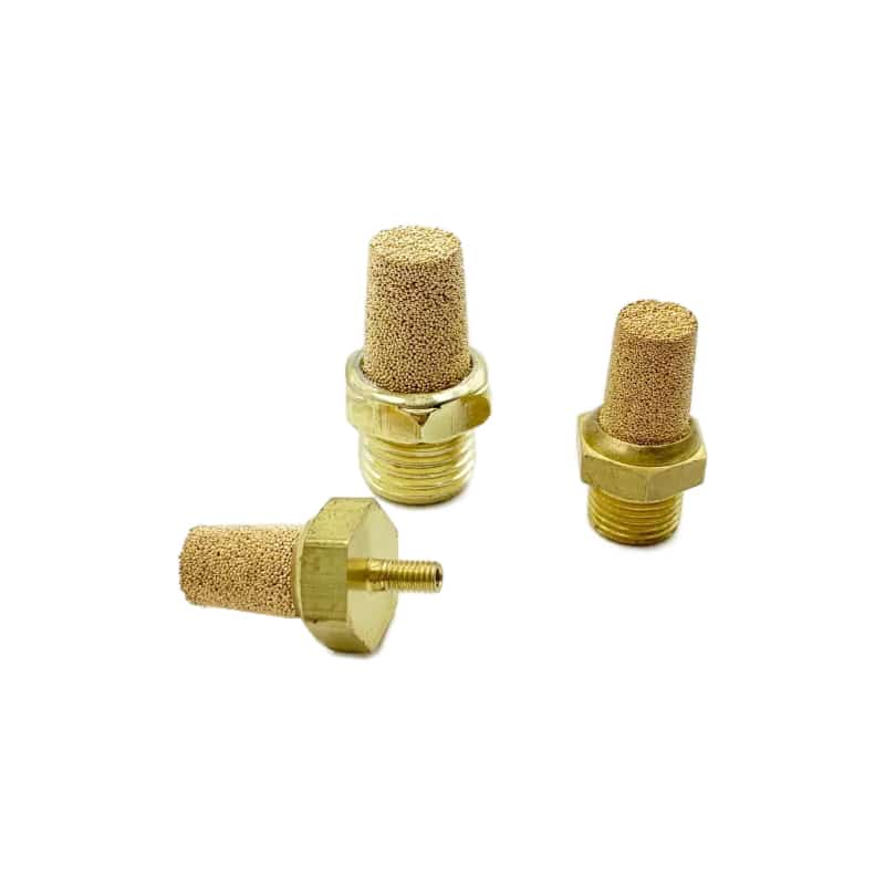
Sintered bronze elements distribute exhaust through interconnected pores. Their acoustic behavior and pressure loss arise from the same porous structure.
A finer or thicker porous element may increase dissipation, but it can also slow chamber emptying. Contamination can move the operating point over time by blocking pores. If exhaust performance changes after service, measure the valve-port pressure and cycle time before assuming the cylinder or directional valve has failed. The back-pressure guide explains the system consequences of a restricted exhaust path.
Why Do Practical Silencers Combine Both Mechanisms?
A 2023 Applied Acoustics experiment combined porous polyurethane with a slit structure inspired by shark gills. The tested biomimetic design improved noise reduction by about 6 dB relative to the comparison silencer while increasing exhaust time by about 2%. Those are prototype-specific results, but they demonstrate why hybrid designs are attractive.
One stage can distribute the incoming jet, another can create reactive effects, and porous material can dissipate the remaining acoustic energy. The housing also protects the media and establishes the effective inlet and outlet areas. These functions are difficult to separate in a compact threaded component.
Hybridization does not guarantee a better product. The 6 dB and 2% figures came from one experimental configuration and test arrangement (Applied Acoustics). They should not be transferred to a different port size, material, valve, pressure, or duty cycle.
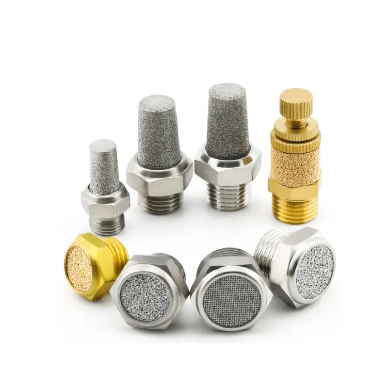
Commercial mufflers use different porous elements, housings, and outlet areas. External appearance alone cannot establish insertion loss or flow capacity.
The engineering question is therefore not “Which mechanism is best?” It is “Which tested construction meets the acoustic requirement without creating unacceptable exhaust restriction, contamination sensitivity, size, or maintenance burden?”
Which Numbers Make Two Pneumatic Silencers Comparable?
Festo lists 59 dB(A) and 1,700 L/min for a G1/8 UC silencer, while its U family lists 76 dB(A) and 3,300 L/min for a G1/4 model. Both cite 6 bar and a 1 m sound distance. A lower sound number alone does not prove a superior substitute.
Start by identifying the acoustic quantity:
- Sound pressure level: the noise measured at a stated position, distance, pressure, and operating event.
- Insertion loss: the level difference between a defined open-exhaust baseline and the same setup with the silencer installed.
- Frequency spectrum: octave-band, one-third-octave, or narrowband data showing where attenuation occurs.
- Time history: peak, fast/slow response, or event-integrated data showing how a short exhaust pulse was evaluated.
For a controlled before-and-after test, insertion loss is:
where:
- is insertion loss in decibels;
- is the sound pressure level for the defined open-exhaust reference;
- is the sound pressure level after installing the silencer.
Both measurements must use the same microphone position, weighting, time response, supply condition, valve, actuator load, and cycle definition. Can one isolated number rank every silencer? Usually not. Because decibels are logarithmic, don’t calculate a simple arithmetic percentage from a dB difference.
Two catalog entries can report the same dB(A) value and still behave differently on a machine. One may attenuate the dominant exhaust band while another shifts energy into a less penalized A-weighted band. Pair the overall value with spectral data when tones, repeated pulses, or hearing-protection decisions matter.
SMC’s AN documentation illustrates another comparison trap: the manufacturer reports 30 dB(A) noise reduction for a new model and 25 dB(A) for an existing compact model in its own comparison (SMC AN). Those are model-specific reduction values, not the output sound pressure levels used in the Festo examples. Keep unlike metrics in separate columns.
Flow Restriction Is the Other Half of Silencer Performance
ISO 6358-1 defines steady-state methods for testing compressible-gas flow through pneumatic components, while the silencer event studied in 2013 was transient. This difference means a catalog flow coefficient can support component comparison, but it does not by itself predict cylinder exhaust time, peak port pressure, or the sound history of one machine cycle.
The silencer sits downstream of the valve’s exhaust metering edges, internal passages, manifold gallery, fittings, and any exhaust tubing. The complete series path controls how quickly the cylinder chamber can empty. A restrictive element can increase exhaust-port pressure, reduce the net pressure available to move the piston, and extend stroke time. The valve pressure-drop guide explains the upstream part of that series path.
Check both the new and end-of-service states:
| Check | What to record | Why it matters |
|---|---|---|
| Published flow data | test pressure, standard reference condition, coefficient or flow, port size | establishes a comparable catalog baseline |
| Exhaust time | pressure decay or time from valve command to chamber threshold | captures the transient event directly |
| Cylinder motion | stroke time, end-of-stroke speed, cushioning behavior | reveals machine-level consequences |
| Valve exhaust pressure | peak and decay at the exhaust gallery or port | exposes restriction that supply pressure cannot show |
| Used-element condition | contamination, condensate, oil, mass change, visual blockage | supports maintenance decisions |
ISO 6358-1 does not prescribe a pneumatic silencer noise test. It addresses steady-state flow-rate characteristics for compressible-fluid components (ISO 6358-1). Acoustic acceptance and machine exhaust-time acceptance therefore need separate criteria.
If the silencer is mounted on a common valve manifold, also check whether simultaneous exhaust events share a restricted gallery. A nominally adequate individual muffler can still become the last restriction in a congested common path. Valve-port function and exhaust routing are covered in the 4-way, 5-port valve guide.
How Should You Test a Silencer on the Machine?
OSHA’s hearing-conservation action level is 85 dBA as an 8-hour time-weighted average, while its Table G-16 permits 90 dBA for 8 hours under the cited general-industry standard. A single near-machine reading is therefore useful diagnostic evidence, but it is not by itself a complete occupational exposure assessment (OSHA 1910.95).
Use a controlled machine test to answer two different questions: did the silencer reduce the intended acoustic event, and did it preserve pneumatic performance?
- Define the machine state. Record supply pressure under flow, regulator setting, valve model, actuator load, stroke, speed-control setting, and ambient conditions.
- Fix the acoustic geometry. Mark the microphone location and orientation. Record distance, A/C/Z weighting, time response, sampling method, background noise, and number of cycles.
- Establish the reference. Use the approved open-exhaust or existing-silencer condition. Control the escaping air safely and do not create an unguarded high-velocity discharge.
- Install the candidate. Keep the valve, fittings, tubing, regulator, and cycle command unchanged.
- Measure repeated events. Record overall sound, spectrum where available, exhaust-port pressure, chamber decay, and cylinder stroke time.
- Test production demand. Include the intended cycle rate and simultaneous consumers at the lowest allowed dynamic supply pressure.
- Set two acceptance limits. Define one for acoustics and another for pneumatic response. Passing one cannot compensate for failing the other.
- Retain a maintenance baseline. Photograph the clean element and record the new-component data so a later restriction can be demonstrated.
In our experience, the most revealing addition is a temporary pressure transducer at the valve exhaust port. A sound meter may show that a new element is quieter, while the pressure trace immediately reveals a slower decay or a growing residual-pressure tail. That evidence prevents acoustics from masking a flow problem.
For personnel exposure decisions, follow the facility’s industrial-hygiene program and applicable jurisdiction. NIOSH recommends an 85 dBA limit over 8 hours with a 3 dB exchange rate, which differs from OSHA’s Table G-16 relationship (NIOSH). Do not mix the two criteria in one pass/fail statement.
What Should an RFQ or Replacement Specification Include?
Festo’s threaded UC models pair 59 to 60 dB(A) with 1,700 to 3,200 L/min, and SMC distinguishes 30 dB(A) reduction from 25 dB(A) in its model comparison. These examples show why an RFQ must state the required metric and test point, not simply request a “30 dB silencer.”
Provide the following information:
- manufacturer and full model of the valve, actuator, and existing silencer;
- exhaust-port thread, available envelope, orientation, and environmental exposure;
- working fluid, supply pressure range, temperature, and expected contamination;
- cylinder bore, stroke, load direction, commanded stroke time, and cycle rate;
- whether multiple stations exhaust simultaneously through a shared gallery;
- required sound-pressure level or insertion loss, weighting, distance, and test event;
- required flow coefficient or acceptable exhaust-time and port-pressure limits;
- housing and media material requirements, including corrosion or washdown constraints;
- inspection interval, replacement method, and evidence that indicates blockage;
- applicable machine-risk and occupational-noise requirements.
Is matching the thread enough? No. Two G1/4 silencers can use different porous media, active surface area, housing volume, and published acoustic metrics. Confirm the complete model data and test the replacement on the real exhaust event.
Silencer selection does not reduce to one arithmetic output. General flow calculations cannot replace manufacturer data plus a transient machine test. For a component review, send the model numbers, pressure trace, cycle data, and measurement conditions through the technical contact page.
Pneumatic Silencer Engineering FAQs
The referenced Festo and SMC catalogs report figures such as 59 dB(A), 1,700 L/min, and 30 dB(A) reduction, but those values use different products and acoustic quantities. The five answers below preserve that distinction and focus on conclusions supported by mechanism, test conditions, and machine measurements.
Is a diffusion silencer different from an absorption silencer?
Not necessarily. The 2013 sintered-bronze study treated porous flow resistance and acoustic behavior in one model. Diffusion describes distribution of the exhaust flow, while absorption describes energy loss within dissipative material. A sintered-metal element can perform both functions, and chambered or perforated features may add reactive attenuation.
Does a lower dB(A) rating always mean a better pneumatic silencer?
No. Festo lists 59 dB(A) and 1,700 L/min for one G1/8 UC model under stated conditions. First confirm whether a number is output sound pressure or insertion loss, then compare pressure, microphone distance, weighting, port size, flow, and test event. Different conditions invalidate a direct ranking.
Can a pneumatic silencer slow a cylinder?
Yes. A 2023 prototype test reported about 2% more exhaust time while improving noise reduction by roughly 6 dB against its comparison silencer. Those figures aren’t universal. Measure stroke time and port pressure with the candidate installed, then repeat after service exposure because porous media can become restricted.
How do I compare insertion loss with a catalog sound-pressure value?
Don’t treat them as one quantity. SMC reports 30 dB(A) noise reduction for one cited model, while Festo reports 59 dB(A) sound pressure for a UC model. Insertion loss is a reference difference; sound pressure is measured output. Compare candidates by repeating both under one controlled method.
Should I remove a blocked silencer to restore production speed?
Only as a controlled diagnostic under an approved safe procedure. OSHA’s hearing-conservation action level is 85 dBA over 8 hours, and an open exhaust can also create a high-velocity jet. If removal changes the pressure trace or stroke time, replace or resize the component and correct the contamination cause.
Sources and Technical References
These 8 primary or manufacturer sources separate research results, flow standards, model data, and occupational-noise criteria. The 2013 paper and 2023 study support the mechanism discussion; ISO 6358-1 addresses steady flow; Festo and SMC supply model-specific examples; OSHA and NIOSH state different exposure criteria.
- Study on acoustical properties of sintered bronze porous material for transient exhaust noise of pneumatic system, Journal of Sound and Vibration, 2013.
- Experimental analysis of biomimetic silencer to reduce exhaust noise in pneumatic devices, Applied Acoustics, 2023.
- Festo UC silencers technical data.
- Festo U silencers technical data.
- SMC AN silencer product comparison.
- ISO 6358-1, compressible-fluid flow-rate characteristics.
- OSHA 29 CFR 1910.95, Occupational noise exposure.
- NIOSH, Understand Noise Exposure.