

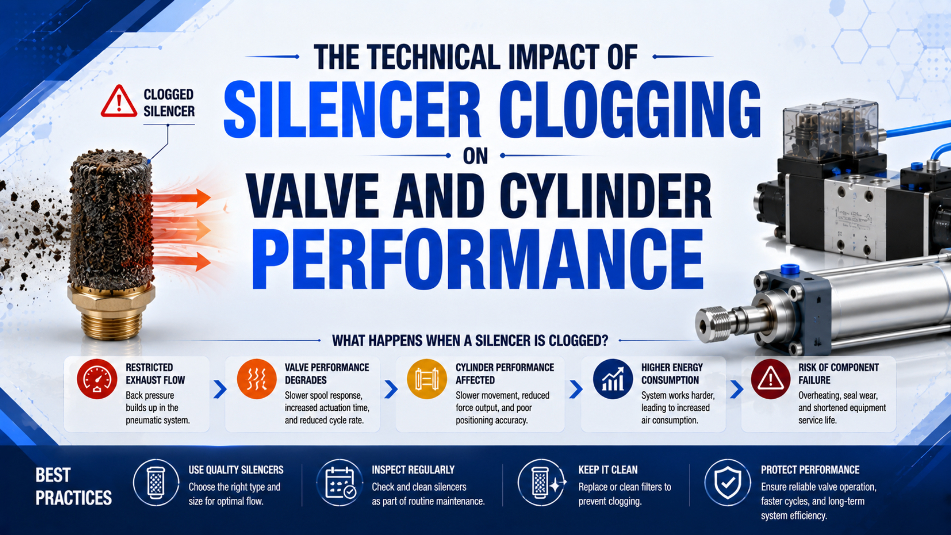
Silencer clogging restricts the valve’s exhaust path, raises pressure in the chamber that should be venting, and can slow one cylinder direction while reducing the pressure-force difference available for motion. Confirm the fault with dynamic pressure and stroke-time measurements. A dirty-looking silencer or quieter exhaust note is not proof by itself.
This article treats the silencer as one component in the complete exhaust circuit. For the broader noise-control and selection topic, use the pneumatic muffler guide. The narrower task here is to separate silencer clogging from valve, flow-control, tube, cushion, and mechanical faults.
Key Takeaways
- Festo lists G1/8 silencers from 1,340 to 2,050 L/min at 6 bar inlet pressure.
- Exhaust pressure reduces net cylinder force on the opposing effective area.
- Compare a suspect silencer with an identical known-good part under the same loaded cycle.
- Use condition-based service, not a universal replacement interval.
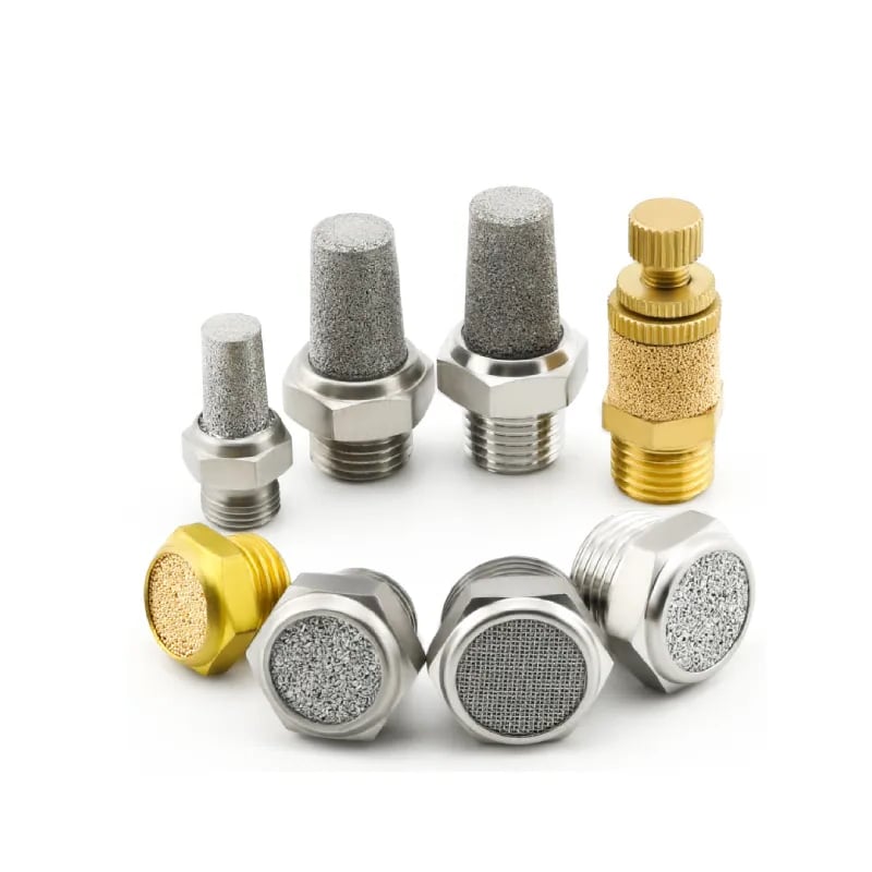
The sintered bronze pneumatic silencer family illustrates why appearance alone is insufficient. Similar threaded parts can use porous metal, wire mesh, or an adjustable element, and each construction has its own cleanability and flow rating.
What Does Silencer Clogging Change in a Pneumatic Circuit?
Festo’s 2024 Silencer U catalog lists 1,340 L/min for one G1/8 die-cast model and 2,000 L/min for a G1/8 polymer male-thread model, both measured at 6 bar inlet pressure. The same nominal connection can therefore represent different clean-state capacity before contamination is considered (Festo Silencer U, 2024).
Silencer clogging is contamination, deformation, icing, or physical blockage that reduces the usable exhaust conductance below the requirement of the operating cycle. The restriction sits downstream of the valve’s exhaust gallery, but its pressure effect appears upstream, between the cylinder chamber and the blocked outlet.
Exhaust back pressure is the pressure retained in a chamber or passage that should be venting toward atmosphere. It becomes a fault when it exceeds the level intended by the circuit and changes force, speed, or venting time.
During cylinder extension, one chamber receives supply air while the other exhausts. During retraction, those roles reverse. A restriction at exhaust port EA may therefore affect one direction more than EB. A shared manifold silencer can affect several valves or both directions, depending on the internal manifold layout.
Start with the slow direction. If only retraction becomes slow, trace the cap-end exhaust path used during retraction. If both directions slow together, inspect shared exhaust hardware, shared supply pressure, and mechanical load before blaming one local silencer.
A clogged silencer is not diagnosed by its thread size or color. It is diagnosed by a repeatable change in the pressure-time behavior of the exhaust path. This distinction prevents unnecessary cylinder replacement when the fault is outside the actuator.
How Does Exhaust Back Pressure Reduce Speed and Net Force?
Festo states that back pressure creates an opposing force and occurs particularly when exhaust flow controls are used or the exhaust port is constricted. Its guidance also warns that friction varies with lubrication, operating pressure, back pressure, and seal design, so a universal force-loss percentage is not transferable between machines (Festo General Operating Conditions, 2022).
For a moving double-acting cylinder, a practical force balance is:
Here, is the force available before external load and acceleration requirements. and are the pressures measured at the two cylinder ports during motion. and are the effective piston areas for that direction, and is the installed mechanical resistance.
Use one consistent unit system. Pressure in MPa multiplied by area in mm² gives force in newtons. Gauge pressure is suitable when atmosphere is the common reference on both sides. For a single-rod cylinder, extension and retraction use different areas, so the same exhaust pressure does not remove the same force in both directions.
Speed changes because the venting chamber cannot empty at the rate demanded by piston motion.
Air leaves more slowly. Pressure stays behind the piston, so the useful pressure difference shrinks. The motion then settles at a lower speed or becomes sensitive to load. The exact change depends on the complete circuit, not an assumed “50% clogged” label.
The cylinder force-loss calculation develops the two-chamber equation in detail. For the wider distinction between supply pressure drop and exhaust pressure, use the pneumatic back-pressure guide.
What Measurements Confirm a Clogged Silencer?
ISO 6358-1 defines steady-state methods for determining the flow characteristics of pneumatic components, while ISO 6358-3 calculates system behavior from components and piping with known characteristics. Those standards support a measurement-based conclusion: one visual inspection cannot identify which series restriction controls the installed circuit (ISO 6358-1, 2013; ISO 6358-3, 2014).
Use the same loaded cycle for every comparison:
A known-good substitution test is a controlled comparison in which only the suspect silencer is replaced by an identical verified part. Keeping every other setting fixed makes the pressure and timing change attributable to that component.
- Record the machine state, payload, supply pressure, regulator setting, flow-control positions, cushion settings, and air temperature.
- Measure extension and retraction time separately.
- Record valve-inlet pressure during motion.
- Record pressure at both cylinder ports on the same time base.
- Shut down, isolate, and release stored pneumatic energy according to the machine procedure.
- Replace the suspect silencer with an identical, clean, known-good part.
- Repeat the same loaded cycle without changing any other setting.
The strongest confirmation is directional and repeatable: the exhausting-chamber pressure falls and the affected stroke time returns toward its established baseline after only the silencer changes. If pressure and timing do not improve, the silencer was not the dominant restriction.
Do not use open exhaust as the default test. Removing a silencer can expose personnel to hazardous noise, expelled oil mist, particles, or unexpected actuator speed. A rated known-good replacement preserves the intended exhaust function while isolating the variable under test. ISO 4414 covers pneumatic-system hazards and maintenance considerations at the system level (ISO 4414, 2010).
ISO 20145:2026 now defines both steady-state and discharge methods for measuring exhaust-silencer acoustic pressure. That distinction also explains why sound alone is a weak clogging indicator: a quieter exhaust pulse may accompany restriction, but acoustic level does not directly quantify the remaining pneumatic conductance (ISO 20145, 2026).
Keep two baselines for high-cycle equipment: loaded stroke time and exhausting-port pressure. A cycle-time trend says performance changed. The synchronized pressure trace identifies whether the change occurred in the supply path, exhaust path, or mechanics.
Distinguishing Silencer Clogging from Other Restrictions
SMC publishes effective areas from 35 to 960 mm² across its AN standard silencer range, while its compact and high-noise-reduction variants use different values. This model spread shows why a suspected restriction must be compared with the exact part number and active flow path, not with another silencer that merely has the same thread (SMC AN Series, accessed 2026).
For example, matching two 1/4-inch threads proves connection compatibility. It does not prove equal clean-state conductance, equal noise reduction, or equal tolerance to contamination.
| Measurement during the slow stroke | Most likely interpretation | Next isolation step |
|---|---|---|
| Valve-inlet pressure falls sharply | Upstream FRL, supply tube, branch, or shared manifold is limiting | Measure progressively upstream under the same demand |
| Drive-port pressure is low while inlet pressure is stable | Valve supply path, fitting, tube, or supply-side flow control is restrictive | Compare pressure immediately before and after the suspected component |
| Drive pressure is adequate and exhausting-port pressure is high | Exhaust-side flow control, valve gallery, tube, fitting, or silencer is restrictive | Substitute the silencer first, then move upstream |
| Exhaust pressure falls with a known-good silencer and time improves | The removed silencer was the dominant restriction | Inspect contamination source and replacement compatibility |
| Exhaust pressure remains high with a known-good silencer | The restriction is upstream of the silencer or the replacement is undersized | Check meter-out control, valve path, adapters, and shared exhaust |
| Both chamber pressures look normal but motion remains slow | Load, alignment, guides, cushions, seals, or mechanical friction may control motion | Separate the actuator from the external mechanism when safe |
The valve itself can be restrictive even when its exhaust connection fits. Compare the active-path data using the port size versus internal orifice analysis and the valve pressure-drop method.
Meter-out controls deserve special attention. They intentionally retain exhaust pressure to stabilize motion. If a silencer is installed downstream, the two restrictions act in series. Do not open the flow control to compensate for a clogged element and leave it there; replace or service the faulty component, then restore and validate the original speed setting. The meter-in versus meter-out guide explains the control boundary.
Which Damage Claims Are Physically Defensible?
Parker defines cylinder thrust from operating pressure and effective area, while Festo states that exhaust back pressure partially cancels effective force. These sources support slower motion and lower available force. They do not establish that every clogged silencer causes valve-seat erosion, spring fatigue, body cracking, solenoid overload, or cylinder overheating (Parker Engineering Data, accessed 2026; Festo, 2022).
The direct effects are simpler:
- higher residual pressure in the exhausting chamber;
- less pressure-force difference across the piston;
- longer or direction-dependent stroke time;
- altered meter-out behavior;
- delayed venting of connected volume, including downstream tubes, manifolds, or pilot passages that share the exhaust route;
- possible failure to meet the machine’s validated timing or pressure acceptance limits.
Damage needs more proof. Compare the measured pressure, temperature, duty, and switching behavior with the exact valve, cylinder, and silencer specifications. If a limit is exceeded, document its size and duration. Without those measurements, a dramatic failure mechanism is speculation.
Safety-related exhaust deserves separate treatment. A clogged accessory on a safety dump or stored-energy release path can delay depressurization. Do not substitute a generic silencer on a safety function based only on thread size. Use the approved component configuration and validate the machine’s required exhaust time under its safety procedure.
Contamination and Service Strategy
Norgren’s 2024 MA/MB catalog identifies a cleanable brass-mesh element and publishes model-specific Cv and sonic-conductance values. Festo publishes porous bronze and polyethylene versions with different clean-state flow ratings. These manufacturer distinctions mean cleaning permission belongs to the part number, not to the generic words “metal silencer” or “plastic silencer” (Norgren MA/MB, 2024; Festo Silencer U, 2024).
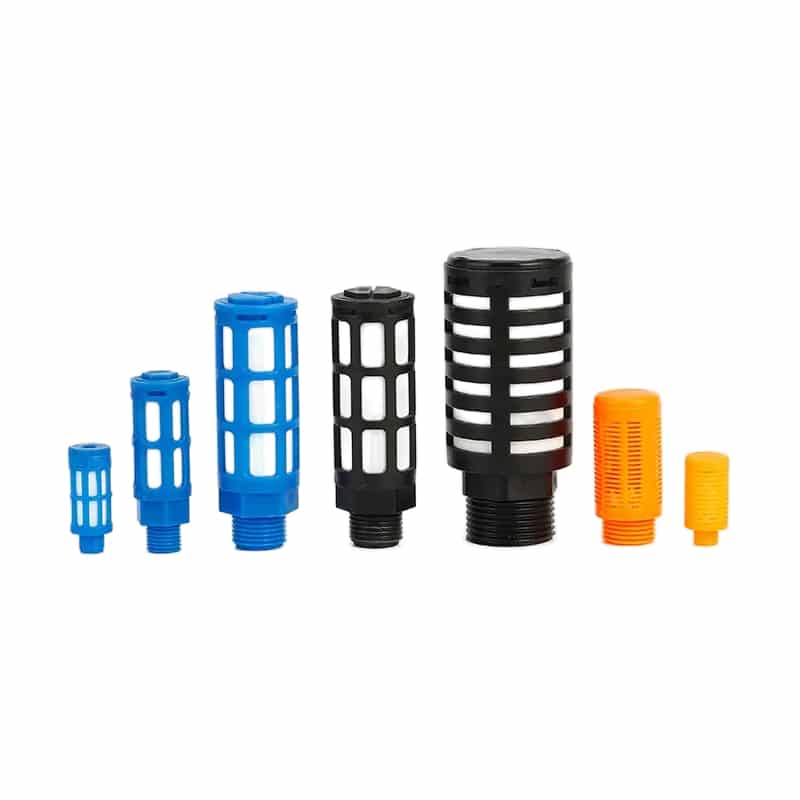
The plastic pneumatic silencer family shows another common construction. Porous polymer, sintered metal, wire mesh, and exhaust-cleaner cartridges should not share one cleaning solvent or service rule.
Common contamination paths include:
- oil carryover from intentional lubrication or compressor contamination;
- liquid water and corrosion products;
- pipe scale, seal fragments, thread debris, or degraded hose particles;
- dust, coolant, washdown residue, adhesive mist, or process powder reaching the outlet from the surrounding machine environment and blocking the element from outside;
- ice where moisture remains and the exhaust cools below the permitted condition.
Norgren specifies that its MA/MB supply must be dry enough to prevent ice below 2°C. That is a model-family condition, not a universal freezing threshold for every installation. Check the selected silencer’s medium, temperature, material, and cleaning instructions before choosing a corrective action.
Use condition-based service:
| Condition | Action |
|---|---|
| Cleanable element, approved cleaning method, body undamaged | Clean according to the manufacturer, dry fully, and retest flow behavior |
| Disposable or non-serviceable construction | Replace with the exact approved part or a documented equivalent |
| Cracked body, deformed thread, damaged diffuser, corrosion, or unknown material compatibility | Replace; do not attempt recovery |
| Cleaning does not restore pressure and stroke-time baselines | Replace and inspect the upstream contamination source |
| Repeated clogging in a short operating interval | Review air preparation, lubrication, environmental exposure, and shared exhaust design |
Never blow a removed element toward personnel or reinstall a solvent-wet silencer. Isolate and depressurize the machine first. Confirm that the cleaning agent, drying method, and disposal route are permitted for the exact material and captured contaminant.
Replacing the silencer fixes the restriction but not the cause. Photograph and retain the removed element, note which face is contaminated, and record the medium present. Contamination concentrated on the internal face points toward the pneumatic circuit; contamination on the external face points toward the surrounding process.
How Should Maintenance Teams Set Acceptance Criteria?
Festo’s G1/8 Silencer U variants span 1,340, 2,000, and 2,050 L/min under the catalog’s stated 6 bar inlet condition. A thread-only replacement can therefore change clean-state performance before service begins. Acceptance criteria should preserve the installed cycle, not merely connection size (Festo Silencer U, 2024).
Record these fields for each serviced exhaust path:
- valve and silencer full part numbers;
- exhaust port identity, such as EA, EB, or common exhaust;
- thread standard and configured adapters;
- published flow value and its test condition;
- normal loaded extension and retraction time;
- valve-inlet and both cylinder-port pressure traces captured on one synchronized time base during the exact loaded stroke;
- flow-control and cushion settings;
- air quality, lubrication state, temperature, and visible contamination;
- cleaning method or replacement part;
- post-service pressure and timing results.
Avoid a universal monthly or annual replacement rule. A clean enclosure with dry air and low cycling does not age an element like an oily, dusty, high-cycle exhaust. Start with the manufacturer’s inspection guidance, then shorten or lengthen the internal interval from measured drift and observed contamination.
The replacement passes when the machine meets its documented loaded stroke times, the exhausting-port pressure returns to its accepted range, and no new noise, leakage, or motion instability appears. If tubing and fittings also changed, use the hose and fitting flow guide to keep those variables in the acceptance record.
Silencer Clogging FAQs
Festo lists three G1/8 silencer constructions between 1,340 and 2,050 L/min at 6 bar inlet pressure. That spread is why these answers avoid universal back-pressure limits, cleaning counts, and replacement intervals. The exact part, flow direction, contamination, operating cycle, and measured pressure trace govern the decision.
Can a clogged silencer reduce pneumatic cylinder force?
Yes. Pressure retained in the exhausting chamber acts on the opposing effective piston area and reduces net pressure force. The amount depends on measured exhaust pressure, cylinder geometry, direction, and friction. Calculate both chamber pressure-area terms instead of applying a generic percentage to the cylinder’s theoretical force.
Why does a clogged silencer slow only one cylinder direction?
Each motion direction uses a different valve supply and exhaust path. A silencer on EA may affect the stroke that vents through EA while EB remains normal. Trace the active spool state and cylinder chamber for the slow direction, then measure that chamber’s pressure during motion.
Is removing the silencer a safe diagnostic test?
Not as a default procedure. Open exhaust can increase noise, release oil mist or particles, and allow the actuator to accelerate unexpectedly. Isolate stored energy and substitute an identical known-good silencer instead. Any open-exhaust test needs a machine-specific risk assessment and controlled test procedure.
Can every pneumatic silencer be cleaned and reused?
No. Norgren identifies specific brass-mesh models as cleanable, but that permission does not apply automatically to porous plastic, sintered metal, paper, or exhaust-cleaner elements. Follow the exact manufacturer’s material and cleaning instructions. Replace damaged, non-serviceable, or chemically incompatible parts.
What should be measured after replacing a clogged silencer?
Repeat the same loaded extension and retraction cycles while recording valve-inlet pressure, both cylinder-port pressures, and stroke time. Keep flow controls, cushions, supply settings, and payload unchanged. The replacement is effective when the affected exhaust pressure and timing return to the machine’s documented acceptance range.
Sources and technical references
- ISO, ISO 6358-1:2013 Pneumatic fluid power, steady-state flow test methods for pneumatic components. Retrieved 2026-07-22.
- ISO, ISO 6358-3:2014 Pneumatic fluid power, calculation of flow characteristics for systems of components and piping. Retrieved 2026-07-22.
- ISO, ISO 20145:2026 Pneumatic fluid power, acoustic test methods for exhaust silencers. Retrieved 2026-07-22.
- ISO, ISO 4414:2010 Pneumatic fluid power, pneumatic-system safety and maintenance principles. Retrieved 2026-07-22.
- Festo, General Operating Conditions, force, friction, and exhaust back-pressure guidance. Retrieved 2026-07-22.
- Festo, Silencer U, flow, sound-pressure, material, and operating-condition data. Retrieved 2026-07-22.
- SMC, Series AN Silencer, effective area, port, noise-reduction, and operating data. Retrieved 2026-07-22.
- IMI Norgren, MA and MB Series Heavy Duty Silencers, conductance, material, and cleanable-element data. Retrieved 2026-07-22.
- Parker, Pneumatic Actuator Products Engineering Data, cylinder thrust and dynamic sizing guidance. Retrieved 2026-07-22.