

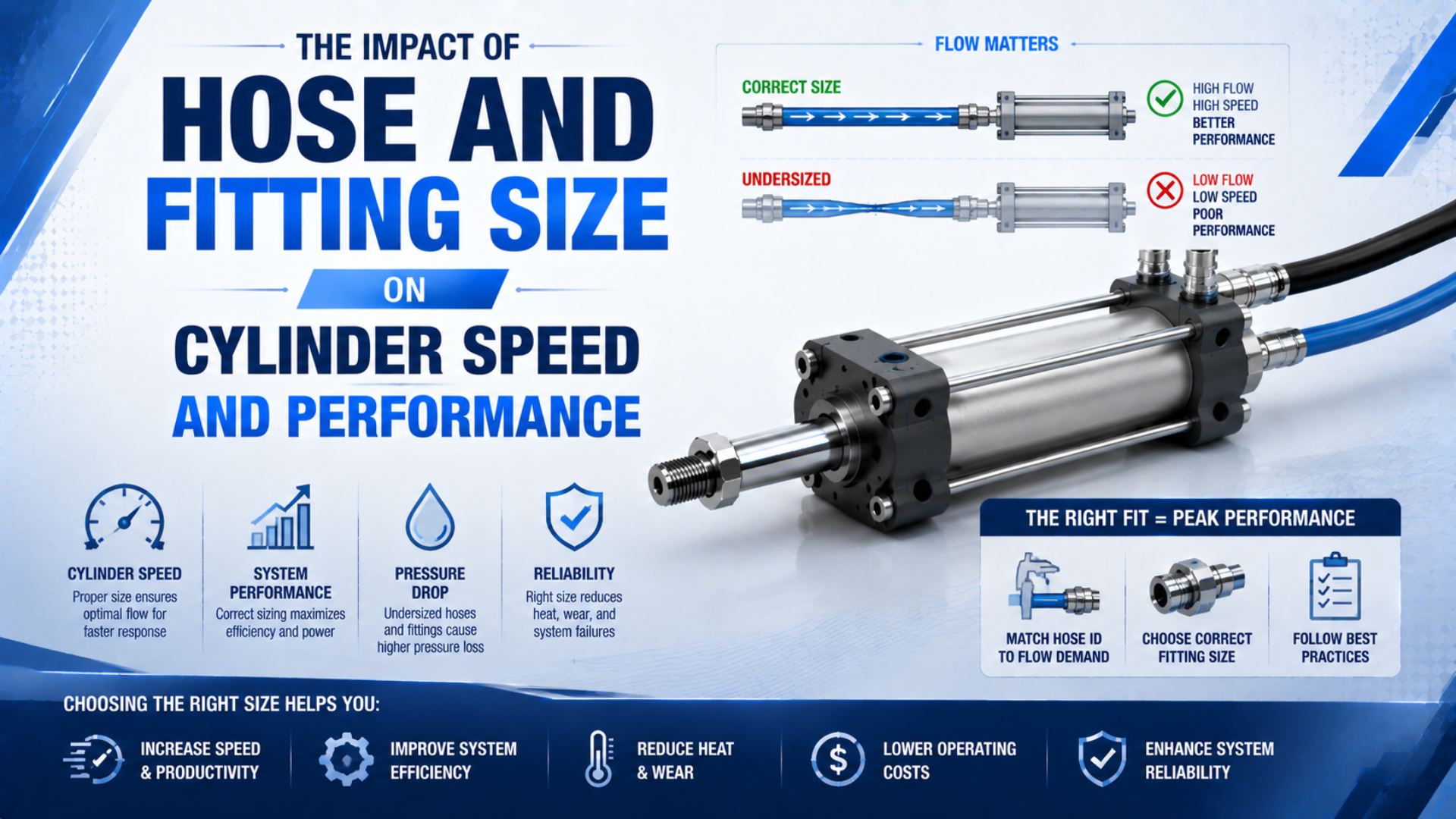
Hose and fitting size affects pneumatic cylinder speed only when it limits the flow needed to fill one chamber and empty the other. Start with bore, stroke, motion direction, and target stroke time. Then compare that demand with the actual tube ID and the tested capacity of every fitting in the active supply and exhaust paths. A larger nominal connection will not improve speed if the valve, speed controller, cylinder port, or silencer remains the controlling restriction.
For complete machine-branch commissioning, including the FRL and shared manifold, use the broader tubing and fitting configuration guide. This article stays focused on the connection between one cylinder’s target motion and its required flow path.
Cylinder connection sizing is the process of matching a cylinder’s peak extension and retraction demand to the documented capacity of its valve-to-port supply and exhaust paths. It begins with chamber volume and target stroke time, not a universal tube-to-port ratio. The comparison must use actual tube ID, tube length, configured fitting geometry, valve path, speed-control direction, and exhaust hardware. A satisfactory design maintains the required chamber pressure and stroke time during the loaded motion without creating harmful exhaust back pressure or end-of-stroke impact. Because nominal tube OD and thread size are mechanical interface labels rather than flow ratings, the final choice requires both supplier flow data and a dynamic pressure test on the assembled circuit. This makes the result traceable during future substitutions and maintenance.
Key Takeaways
- Calculate extension and retraction demand before selecting tube or fittings.
- Tube OD, thread size, and cylinder port size are not flow ratings.
- Compare the exact fitting’s effective area, sonic conductance, critical pressure ratio, or pressure-flow curve.
- Check supply restriction and exhaust back pressure during the moving stroke.
- Stop upsizing when another component becomes the limiting passage.
Cylinder Speed Depends on Working Flow and Effective Area
Cylinder speed is set by chamber flow, effective piston area, load, and the pressure difference available while the piston is moving. Hose and fittings matter because they can reduce fill flow, trap exhaust air, or delay pressure buildup, but they are only part of the active circuit.
SMC summarizes the basic distinction: cylinder output force is a function of pressure, while cylinder speed is a function of air flow. It also notes that meter-out control at the actuator exhaust is the common way to regulate speed (SMC, accessed 2026).
For a first kinematic check:
Here, is piston speed, is the volume entering the active chamber at its actual pressure and temperature, and is piston area for extension or annular area for retraction.
This relation does not mean that a catalogue value in NL/min or SCFM can be divided directly by piston area. Catalogue flow is normally stated at a reference condition, while the chamber contains compressed air. Convert both quantities to the same pressure and temperature basis first.
The cylinder also has two simultaneous flow problems. The driving chamber must fill fast enough, and the opposite chamber must exhaust without excessive back pressure. A large inlet tube cannot compensate for a nearly closed meter-out control or a clogged exhaust silencer.
How Much Flow Does the Target Stroke Time Require?
Required working flow starts with the swept chamber volume divided by the target stroke time. Calculate extension and retraction separately because the piston rod reduces the rod-side area.
For extension:
For retraction:
Working-volume flow is the chamber volume that must be filled or exhausted per unit time at the chamber’s actual operating condition. Its ideal demand is:
In these equations, is bore diameter, is rod diameter, is stroke, and is the target travel time. A first-pass isothermal conversion to reference or free-air flow is:
Both pressures must be absolute. State the reference condition because standard gas-flow units do not always use the same reference temperature. NIST documents these pressure and gas-flow conversion differences (NIST, updated 2025).
Worked example: a 40 mm bore cylinder
Consider a double-acting cylinder with these inputs:
| Input | Value |
|---|---|
| Bore | 40 mm |
| Rod diameter | 16 mm |
| Stroke | 200 mm |
| Target stroke time | 0.50 s |
| Estimated chamber pressure | 6 bar gauge |
The ideal extension chamber volume is about 0.251 L. Completing the stroke in 0.50 s requires about 30.2 L/min at the working condition. Using 7 bar absolute and a 1 bar absolute reference gives an ideal free-air demand of about 211 L/min.
The rod-side swept volume is about 0.211 L, corresponding to about 177 L/min of ideal free-air demand under the same assumptions. These figures are preselection estimates, not guaranteed cycle results. Tube and cylinder dead volume, temperature change, valve response, cushion restriction, seal friction, load acceleration, and pressure variation still affect the measured stroke.
If the required free-air flow is known, the Tube ID Calculator can screen the internal diameter needed at a selected working pressure and velocity. Use its result as a starting point, then verify pressure-flow performance with the exact component data.
Nominal Hose and Port Size Can Mislead You
A printed tube or port size does not reveal the smallest internal passage that controls flow. Tube inside diameter is the diameter available to the moving air after wall thickness is subtracted. Push-in tubing is usually identified by outside diameter, while flow area comes from inside diameter. Wall thickness, material, reinforcement, and manufacturing series can give two tubes with the same OD different IDs.
Keep these dimensions separate:
| Catalogue label | What it describes | What must still be checked |
|---|---|---|
| Tube size | normally outside diameter | actual ID, wall thickness, length, bend radius |
| Cylinder port | thread or interface size | internal drilling and port geometry |
| Fitting thread | mechanical connection | throat, seal, stem, elbow, or reducer passage |
| Valve port | connection size | configured supply and exhaust flow data |
| Flow-control size | body or thread family | free-flow direction and metered-flow capacity |
ISO 14743 covers complete push-in connector assemblies for thermoplastic tube from 3 mm to 16 mm outside diameter. It provides uniform assembly test methods; it is not a cylinder-to-tube sizing table (ISO 14743, 2020).
Avoid rules such as “tube ID must equal half the cylinder-port diameter.” Port size alone says nothing about target stroke time, tube length, chamber pressure, valve capacity, or exhaust restriction. A slow positioning cylinder and a high-speed transfer cylinder can use the same bore but require very different flow paths.
How Should You Compare Pneumatic Fittings?
Compare the exact configured fittings under a common test basis, not generic labels such as standard-flow or high-flow. Useful supplier data include effective area, sonic conductance , critical pressure ratio , Cv with stated gas-flow conditions, or a pressure-flow curve.
SMC’s KQ2 catalogue illustrates why model-level data matters. Its tables list tube OD, connection type, minimum port size, and different effective areas for nylon and polyurethane tubing. Geometry also changes the value, so one percentage cannot describe every straight, elbow, tee, reducer, or quick connector (SMC KQ2 catalogue, accessed 2026).
ISO 6358-1 defines steady-state test methods for pneumatic components with fixed or variable internal flow paths. The standard does not treat a cylinder itself as a steady restriction, and its 2026 amendment adds guidance on measurement uncertainty (ISO 6358-1; 2026 amendment).
When several documented components form one path, ISO 6358-3 provides a method for estimating the system’s steady-state characteristics in both subsonic and choked regions (ISO 6358-3, confirmed 2025). The practical lesson is simple: valid system calculations begin with valid component data.
Do not assume that the visually smallest thread is always the bottleneck. A fitting may have a generous throat while the valve spool window, speed-control needle, quick coupling, or silencer has the lower conductance. Conversely, a large tube attached through a reducer may gain almost nothing.
How Can You Find the Restriction During the Stroke?
Measure pressure while the cylinder is moving, on both the supply and exhaust sides. Dynamic pressure loss is the pressure difference that appears across a component or path during the relevant flow event. An idle regulator gauge can look normal even when the valve inlet collapses during peak flow or the exhausting chamber holds enough back pressure to oppose the piston.
Use this test sequence:
- Record bore, rod, stroke, load direction, target time, and actual time.
- Identify the active valve ports, tube ID and length, fitting models, speed controller, and silencer.
- Measure valve-inlet pressure at P1 and cylinder-port pressure at P2 during the moving part of the stroke.
- Measure exhaust pressure at P3 when a return tube, manifold, flow control, or silencer is suspected.
- Test extension and retraction separately because they use different chamber areas and valve paths.
- Change one item, then repeat the same loaded cycle and compare pressure traces and stroke time.
| Measurement pattern | Likely interpretation |
|---|---|
| P1 drops sharply during both directions | upstream tube, FRL, shared supply, or manifold limitation |
| P1 remains stable but P2 stays low | valve path, supply fitting, speed control, or local tube restriction |
| Driving pressure is adequate but P3 is high | exhaust fitting, meter-out control, valve exhaust, or silencer restriction |
| Pressure is adequate but speed falls near the end | cushion setting, load change, alignment, or mechanical friction |
| Larger tube produces no measurable change | another component is controlling the path |
CAGI advises reducing excessive pressure drop by increasing undersized tubing, minimizing unnecessary length, and correcting restrictions before raising compressor pressure. Its often-cited 10% value covers the plant path from compressor discharge to point of use; it is not an automatic allowance for one cylinder branch (CAGI Pressure Drop Technical Brief, accessed 2026).
If the pressure ratio across a component suggests a flow ceiling, follow the separate choked-flow cylinder-speed guide. Use absolute pressure for that diagnosis.
When Does a Larger Hose Stop Improving Performance?
Upsizing stops helping when the changed hose no longer consumes a meaningful part of the available pressure or response-time budget. The remaining limit may be the valve, a reducer, the cylinder port, the speed controller, the exhaust path, the load, or the cushion.
Larger is not automatically harmless. A bigger or longer tube increases switched volume, stored compressed air, installation space, and cost. The valve must fill and empty that extra tube volume on every cycle. On a remote valve installation, the additional volume can delay initial pressure response even when steady pressure loss is acceptable.
Use four acceptance checks after any size change:
- minimum cylinder-port pressure during motion;
- exhaust back pressure during the opposite chamber’s discharge;
- loaded extension and retraction time over repeated cycles;
- end-of-stroke impact, cushion entry, and mounting loads.
A faster cylinder carries more kinetic energy into the end cushion. Do not release a speed improvement until cushioning, shock absorption, guarding, and machine risk controls remain acceptable. ISO 4414 provides general safety rules for pneumatic systems and components (ISO 4414).
Do not use higher supply pressure as the first response to a small connection. Higher pressure changes cylinder force, air consumption, impact energy, and component loading. Find the measured restriction first, then verify every affected rating and safety function before changing pressure.
A Practical Hose and Fitting Selection Checklist
Release the connection only when its calculated demand, documented capacity, installation details, and measured stroke result agree. A useful RFQ or commissioning sheet should contain the following information.
| Check | Required evidence |
|---|---|
| Motion | extension/retraction, stroke, target time, repetition rate |
| Cylinder | bore, rod diameter, port specification, load direction, cushion |
| Flow demand | working flow and reference/free-air flow for both directions |
| Tube | supplier, series, material, OD, ID, length, bend radius |
| Fittings | exact model, geometry, thread, minimum passage, tested flow data |
| Valve and controls | active path, conductance or flow curve, meter-in/meter-out setting |
| Exhaust | valve exhaust passage, return tube, manifold, silencer condition |
| Environment | temperature, vibration, abrasion, washdown, chemicals, movement |
| Validation | dynamic pressures, loaded stroke time, repeatability, cushion behavior |
Reject substitutions based only on matching OD and thread. Ask whether the proposed tube changes ID or stiffness, whether the fitting changes effective area, and whether its published value uses the same test conditions as the original.
The correct connection is not the largest item that fits the port. It is the documented combination that passes the required extension and retraction flow, maintains adequate chamber pressure, avoids harmful exhaust back pressure, and meets the measured cycle safely.
For an application-specific review, send the cylinder dimensions, target stroke time, valve model, tube OD and ID, connection layout, and dynamic pressure readings through Contact.
Pneumatic Cylinder Hose and Fitting FAQs
Should tube size match the pneumatic cylinder port size?
Not automatically. Tube size normally identifies outside diameter, while the cylinder port identifies a thread or interface. Neither value states the complete flow capacity. Calculate target extension and retraction demand, obtain the tube’s actual ID, and compare the exact valve, fittings, controls, ports, and exhaust devices under compatible test conditions.
Can an undersized hose reduce pneumatic cylinder force?
Yes, during motion. A restrictive hose or fitting can lower pressure in the driving chamber or increase pressure in the exhausting chamber, reducing the net force across the piston. Static pressure after the cylinder stops may still look normal, so diagnose the problem with chamber-pressure measurements taken during the loaded stroke.
Does a larger pneumatic hose always make a cylinder faster?
No. A larger hose helps only when the existing hose or its connections consume meaningful pressure or response time. Once the valve, speed controller, cylinder port, exhaust path, cushion, or load becomes the controlling limit, further upsizing adds volume and cost without producing a useful speed increase.
How do I compare two pneumatic fittings with the same thread size?
Compare the exact models using minimum passage, effective area, sonic conductance and critical pressure ratio, or matched pressure-flow curves. Check tube material and OD, because the configured assembly can change the published value. Thread size and external body dimensions alone do not establish compressed-air capacity.
Should I raise air pressure when a pneumatic cylinder is too slow?
Not as the first step. Higher pressure changes force, air consumption, impact energy, and component loading, while a restricted exhaust may remain unchanged. Calculate required flow, record valve-inlet and cylinder-port pressures during motion, inspect the exhaust path, and correct the measured bottleneck before reviewing any pressure increase.