

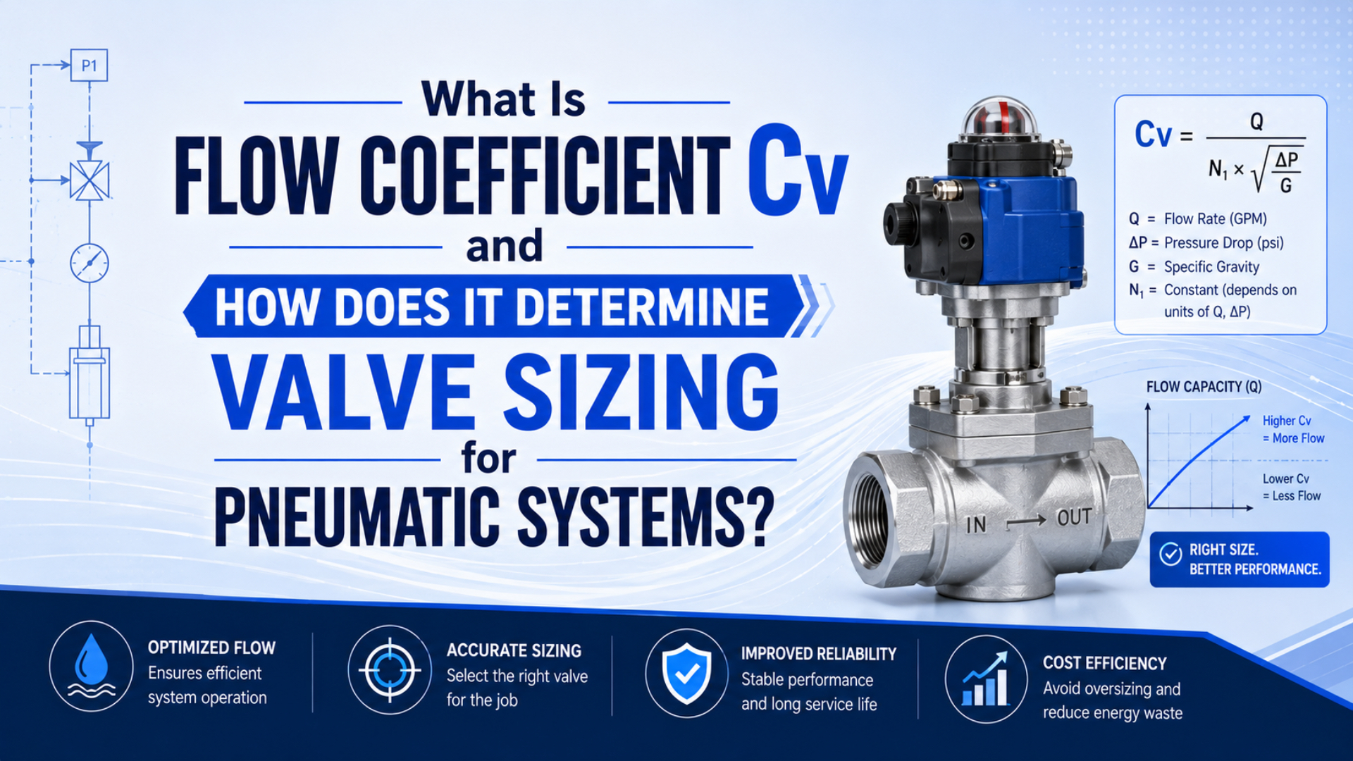
Flow coefficient Cv is a valve capacity rating used to compare how much flow a valve can pass for a given pressure drop. In pneumatic systems, Cv is useful because a valve can have the correct port thread and still be too restrictive for the cylinder stroke time, exhaust path, or manifold demand.
For compressed air, treat Cv as a practical catalog comparison, not the only sizing standard. ISO 6358-1 defines test methods for flow-rate characteristics of pneumatic components using compressible fluids (ISO 6358-1, 2013, confirmed 2022). That matters because air compresses, chokes, expands, heats, and cools differently from water.
Key Takeaways
- Cv helps compare valve capacity, but port size alone does not prove a pneumatic valve can meet the required actuator speed.
- Parker shows a valve-sizing example where a 3-1/4 inch bore cylinder with a 12 inch stroke and 1 second stroke time requires Cv 1.06 at 80 psi.
- CAGI recommends no more than 10 percent pressure drop from compressor discharge to point of use, so valve Cv must be checked with tubing, fittings, filters, and exhaust restrictions.
In our experience, Cv mistakes usually show up after the machine is built. The drawing says 1/4 inch valve, the purchasing note says same port size, and the actuator still misses cycle time because the internal flow path, manifold supply, muffler, or speed controller is smaller than the port label suggests.
What Does Flow Coefficient Cv Mean?
Flow coefficient Cv is a standardized capacity number for a valve flow path. Parker says each flow path through a valve has its own Cv, and its catalog gives flow rating for each valve so engineers can convert job requirements into a required Cv (Parker, 2026).
The common liquid definition is simple: Cv is the number of US gallons per minute of water at 60 F that pass through a fully open valve with a 1 psi pressure drop. That definition gives engineers a common comparison number, even when two valves have the same port thread but different internal geometry.
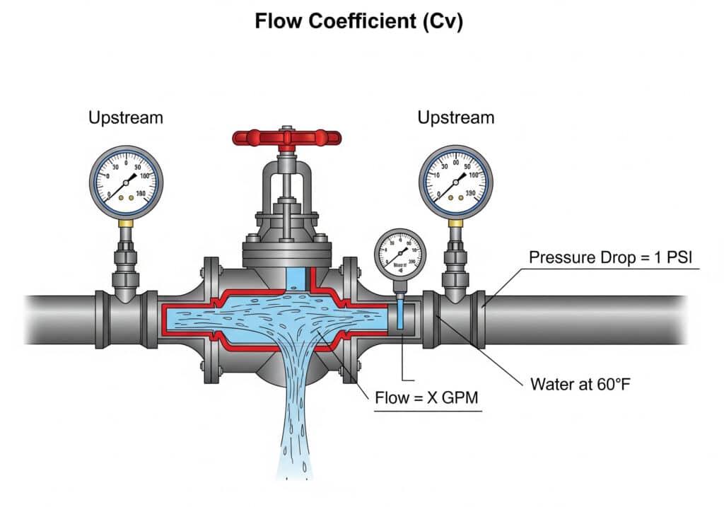
For liquids, the basic relationship is:
Cv = Q x sqrt(SG / DeltaP)
Where:
| Term | Meaning | Typical unit |
|---|---|---|
| Cv | valve flow coefficient | dimensionless catalog rating |
| Q | liquid flow rate | US gpm |
| SG | specific gravity | water = 1.0 |
| DeltaP | pressure drop across valve | psi |
For air, the valve is not moving incompressible water. The same Cv number still helps compare valves, but compressed-air sizing must account for absolute pressure, upstream and downstream pressure, temperature, pressure ratio, fittings, tubing, and possible choked flow.
Why Does Cv Matter for Pneumatic Valve Sizing?
Cv matters because actuator speed depends on how quickly air can enter one chamber and leave the other. Parker’s sizing example converts a 3-1/4 inch bore, 12 inch stroke, 1 second motion, and 80 psi supply into a required Cv of 1.06 (Parker, 2026).
That example is useful because it starts from the motion requirement, not from the valve thread. A valve marked 1/4 inch can have a lower or higher Cv than another 1/4 inch valve, depending on spool design, seal geometry, internal turns, and exhaust path.
Use Cv when the design question sounds like this:
| Design question | Why Cv belongs in the answer |
|---|---|
| Will this cylinder finish the stroke in 1 second? | stroke time sets required air flow |
| Can I replace this valve with the same port size? | port size does not equal internal capacity |
| Why is one direction slower than the other? | supply and exhaust paths can have different Cv values |
| Can one manifold feed several valves at once? | simultaneous demand creates shared pressure drop |
| Is the muffler or speed controller too restrictive? | exhaust Cv can limit cylinder speed |
For rodless cylinders, the same point becomes more visible. A long rodless cylinder contains more air volume than a compact clamp cylinder, so a valve that works on a short stroke may be too small for a long transfer axis.
Cv, Kv, and ISO 6358: Which Rating Should You Trust?
Use Cv or Kv for quick catalog comparison, then prefer ISO 6358 flow-rate data when the component is tested as a pneumatic device. ISO 6358-1 specifies steady-state test methods for pneumatic components using compressible fluids, which is closer to real compressed-air behavior than water-based Cv alone (ISO 6358-1, 2013).
Cv and Kv are not competing engineering philosophies. They are different unit systems for a similar valve-capacity idea. The practical conversion commonly used in pneumatic tools is:
Kv = 0.865 x Cv
Cv = 1.156 x Kv
Use the ratings this way:
| Rating | Best use | Limitation |
|---|---|---|
| Cv | US-market valve capacity comparison | based on a water reference unless the datasheet gives pneumatic test context |
| Kv | metric valve capacity comparison | same caution as Cv when applied to compressed air |
| ISO 6358 sonic conductance and critical pressure ratio | pneumatic component flow testing | not always printed on simple valve datasheets |
| SCFM or NL/min rating | quick air-flow comparison at stated conditions | only useful if pressure and test conditions match your case |
ISA75 covers control-valve standards work related to valves (ISA, 2026). For industrial pneumatics, that standard background is useful, but the immediate check is still specific: what flow data does the valve manufacturer provide, and under what pressure conditions was it measured?
How Do You Estimate Required Cv From Stroke Time?
Start with cylinder demand, then compare candidate valves against that demand. Parker’s published pneumatic valve example uses bore, stroke, time, pressure, area, compression factor, and a constant to calculate required Cv, ending at Cv 1.06 for the stated cylinder case (Parker, 2026).
The sequence is more important than the exact catalog formula:
- Define bore, stroke, working pressure, and target stroke time.
- Calculate the cylinder air demand for the motion.
- Check supply-side valve capacity for filling the chamber.
- Check exhaust-side capacity through the opposite valve path, speed controller, muffler, and tubing.
- Add margin for simultaneous motion, pressure variation, and future speed changes.
Here is a practical sizing table:
| Input | Why it matters | Common mistake |
|---|---|---|
| Bore or effective area | sets chamber volume and force | using outside body size instead of effective area |
| Stroke | sets how much volume must fill or exhaust | ignoring long-stroke rodless axes |
| Stroke time | turns volume into required flow | accepting “fast enough” without a number |
| Working pressure | changes air mass and pressure ratio | using gauge pressure where absolute pressure is needed |
| Valve Cv | limits fill and exhaust capacity | matching only port thread |
| Tube ID and length | adds dynamic pressure drop | using long small-bore tubing after a large valve |
| Muffler and speed control | can dominate exhaust restriction | diagnosing only the supply side |
If the cylinder demand is unknown, do not start by buying a larger valve. Estimate the required flow first. Then compare the valve, fittings, tube, FRL, and exhaust path as one air route.
What Does Cv Miss in a Real Pneumatic Circuit?
Cv misses every restriction that is outside the valve rating. CAGI says well-designed compressed-air systems usually have no more than 10 percent pressure drop between compressor discharge and point of use, and its pressure-drop brief lists piping, filters, dryers, separators, fittings, and hoses as loss sources (CAGI, 2022).
A valve can have enough Cv on paper while the installed circuit remains slow. The common reasons are not exotic:
- The upstream regulator cannot hold pressure during motion.
- The manifold supply gallery is undersized for simultaneous valve shifts.
- Push-in fittings have smaller bores than the tube label suggests.
- Long tube runs add delay and pressure loss.
- A muffler, elbow, or meter-out speed controller restricts exhaust.
- Dirty filters or water separators add pressure drop.
- The valve is sized for one cylinder but now feeds several actuators.
NASA’s compressible-flow reference explains the important boundary: mass flow can reach a limiting maximum when flow becomes sonic at the smallest area (NASA Glenn Research Center, 2023). In plant terms, once a small orifice is choked, adding downstream demand does not make more air pass through that restriction.
That is why the companion article on air flow and pressure conversion in pneumatic systems should be read after this one. Cv gives the valve-capacity number; pressure ratio and compressible-flow behavior explain why the number does not behave like a simple liquid pipe calculation.
How Should You Choose a Valve Cv for a Pneumatic System?
Choose valve Cv by matching required flow, acceptable pressure drop, motion stability, and manufacturer test data. Parker says not oversizing valves saves space and money while still making sure the selected valve can do the job (Parker, 2026).
Oversizing is not always harmless. A much larger valve can make a cylinder start abruptly, create harder end impacts, increase noise, complicate speed control, and waste panel space. Undersizing is easier to notice: slow stroke, weak acceleration, inconsistent timing, or one-direction speed problems.
For a directional valve, check both supply and exhaust. A 4-way 5-port valve has separate paths for each direction, so extend can pass while retract fails. For manual flow control, compare this with meter-in and meter-out control.
What Are the Most Common Cv Sizing Mistakes?
The most common Cv mistake is treating one catalog number as the whole pneumatic circuit. CAGI notes that compressed air is expensive to produce and that 80 percent of leaks are not audible, so pressure loss and wasted flow deserve the same attention as the valve itself (CAGI, 2026).
Avoid these mistakes:
| Mistake | What happens | Better check |
|---|---|---|
| Matching port size only | replacement valve passes less air | compare Cv, Kv, or flow rating at stated conditions |
| Ignoring exhaust Cv | one direction is slow or unstable | check muffler, speed controller, and exhaust path |
| Using liquid Cv math as if air were water | pressure-ratio effects get missed | use pneumatic flow data or ISO 6358 values when available |
| Forgetting simultaneous demand | manifold pressure drops during cycle | measure point-of-use pressure while several valves shift |
| Oversizing without speed control | cylinder starts hard and impacts end stops | combine valve size with meter-out tuning and cushions |
| Trusting static pressure | gauge looks fine before motion | measure dynamic pressure during the stroke |
When a customer reports that “the valve is open but the cylinder is slow,” we ask for three numbers before talking about replacement: required stroke time, point-of-use pressure during movement, and the valve or manifold flow rating. Those three numbers usually separate an electrical fault from a flow-capacity problem.
For broader troubleshooting, use the pressure-drop guide on what causes pressure drop in pneumatic systems. If the valve type itself is still undecided, use the comparison article on pneumatic flow control valve types.
What Should You Send in a Valve Sizing RFQ?
Send enough data for the supplier to size the flow path, not only the connection thread. Parker’s catalog guidance begins with application requirements and then checks required Cv, while CAGI’s pressure-drop guidance keeps the full compressed-air route in scope (Parker, 2026; CAGI, 2022).
Include these details in the RFQ:
- Cylinder type, bore, stroke, and effective area if known.
- Target stroke time and duty cycle.
- Supply pressure at the valve during motion, not only compressor setpoint.
- Valve function, such as 3/2, 5/2, 5/3, normally closed, or normally open.
- Required port size, tube ID, tube length, and fitting type.
- Known Cv, Kv, ISO 6358 data, SCFM, or NL/min rating from the old valve.
- Load direction, vertical axis risk, cushion needs, and speed control method.
- Air quality, pressure dew point, temperature, and contamination concerns.
- Photos of the valve label, manifold, mufflers, fittings, and actuator.
For Bepto replacement work, a good RFQ also includes the old valve brand and model, the machine symptom, and whether the issue appears in one direction or both directions. Use contact support when the same valve feeds a long rodless axis, multiple cylinders, or a cycle-time-critical station.
FAQ
What exactly does Cv mean?
Cv is a valve capacity coefficient. In its common water-reference definition, it indicates how many US gallons per minute of water at 60 F can pass through a fully open valve with a 1 psi pressure drop. In pneumatics, it is a useful comparison number, but compressed-air behavior still needs pressure-ratio and test-condition checks.
Is Cv the same as Kv?
Cv and Kv describe similar valve-capacity ideas in different unit systems. A practical conversion is Kv = 0.865 x Cv, and Cv = 1.156 x Kv. Use the conversion only for first comparison, then check the manufacturer’s pneumatic flow rating, test pressure, and any ISO 6358 data.
Can I size a pneumatic valve from port thread alone?
No. Port thread tells you the connection size, not the internal valve capacity. Two valves with the same port can have different spool geometry, seal design, flow paths, exhaust capacity, and Cv. Start with cylinder flow demand and stroke time, then compare valve flow data.
Why does ISO 6358 matter if my catalog lists Cv?
ISO 6358 matters because it addresses flow-rate characteristics of pneumatic components using compressible fluids. Cv is still helpful for catalog comparison, but ISO 6358 data is closer to compressed-air component behavior when available. For fast cylinders, long tubing, or tight cycle times, ask for both.
Does a higher Cv always make a cylinder faster?
No. A higher Cv can reduce valve restriction, but cylinder speed also depends on supply pressure, tube ID, fitting bore, manifold capacity, exhaust restriction, muffler condition, load, cushions, and speed controls. Once another part of the route is limiting flow, a larger valve alone may not improve motion.
Sources and Retrieval Notes
- ISO 6358-1:2013, pneumatic fluid power test methods for determining flow-rate characteristics of components using compressible fluids. Retrieved 2026-07-08.
- CAGI: Technical Brief on Pressure Drop, 10 percent pressure-drop benchmark, recommended pipe velocity, and filter differential guidance. Retrieved 2026-07-08.
- CAGI: Working with Compressed Air, compressed-air cost, waste, leak, and system-efficiency context. Retrieved 2026-07-08.
- Parker: Pneumatic Valve Catalog Introduction, valve Cv definition, pneumatic sizing formulas, and the Cv 1.06 cylinder example. Retrieved 2026-07-08.
- ISA75 Control Valve Standards Committee, standards scope for valves. Retrieved 2026-07-08.
- NASA Glenn Research Center: Mass Flow Rate Through a Nozzle, choked-flow and maximum mass-flow explanation for compressible flow. Retrieved 2026-07-08.
- AutomationDirect: Understanding Pneumatic Valve Ports and Ways, video background for valve ports and ways. Retrieved 2026-07-08.