

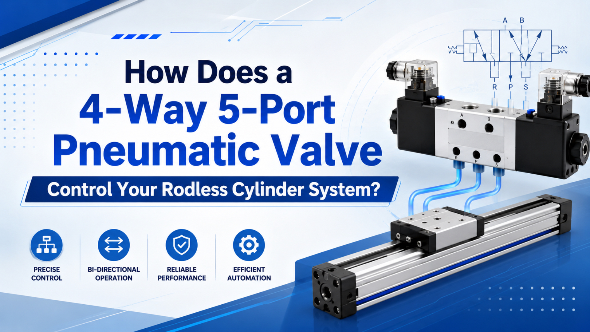
4-way 5-port pneumatic valve is a directional valve that controls a double-acting actuator by sending compressed air to one working port while exhausting the opposite port. Many catalogs describe the common version as a 5/2 valve: 5 ports and 2 spool positions. Tameson lists the 5/2 layout as 1 supply port, 2 cylinder ports, and 2 exhaust ports (Tameson, 2026).
Rodless cylinder is a linear pneumatic actuator where the internal piston moves an external carriage instead of pushing an exposed rod. Valve routing matters because that carriage may travel a long stroke with external tooling. If supply fills slowly or exhaust cannot empty cleanly, the carriage may creep, jump, stall, or hit the end stop harder than expected.
Key Takeaways
- A 4-way 5-port valve is commonly used as a 5/2 valve for two-position rodless cylinder motion.
- The five practical ports are P supply, A and B cylinder ports, plus EA and EB exhaust ports.
- CAGI recommends no more than 10% pressure drop from compressor discharge to point of use, so valve and tubing restrictions belong in the diagnosis.
In our experience, the common field mistake is treating the valve as only an electrical device. The solenoid can shift correctly while the pneumatic circuit still fails. A long rodless cylinder needs enough supply flow, enough exhaust flow, stable point-of-use pressure, and sensor feedback that proves the carriage actually moved.
What Does 4-Way 5-Port Mean?
4-way 5-port usually means a directional valve with 5 physical ports and 2 or 3 spool positions. For the common 5/2 version, Tameson lists 1 pressure supply, 2 cylinder ports, and 2 exhaust ports, which matches the P, A, B, EA, and EB layout used in rodless cylinder circuits (Tameson, 2026).
The naming can look inconsistent because different markets use different language. Some drawings call the same basic device a 4-way valve. Many pneumatic catalogs call it a 5/2 valve. The practical question is simpler: how many ports does it have, and what happens when the spool shifts?
Use these names on the drawing:
| Port label | Common function | Rodless cylinder connection |
|---|---|---|
| P | pressure supply | from FRL, manifold, or valve island supply |
| A | working port A | one rodless cylinder chamber |
| B | working port B | opposite rodless cylinder chamber |
| EA or R | exhaust for A path | muffler, speed control, or exhaust manifold |
| EB or S | exhaust for B path | muffler, speed control, or exhaust manifold |
That table is the part worth printing beside the machine. If A and B are crossed, the carriage moves opposite the PLC command. If EA or EB is restricted, one direction may slow down even when the supply pressure looks correct.
How Do P, A, B, EA, and EB Ports Route Air?
The valve routes air by connecting P to one working port while the other port exhausts. Tameson describes a 5/2 valve with 1 supply port, 2 cylinder ports, and 2 exhaust ports, which is the practical P-A-B-EA-EB map (Tameson, 2026).
In one position, P connects to A and B connects to EB. The rodless cylinder carriage moves toward the side driven by pressure in port A. In the opposite position, P connects to B and A connects to EA. The carriage reverses.
The two exhaust ports are not decoration. They let each direction have its own exhaust path, muffler, speed controller, or manifold route. That is useful when extend and retract need different speeds, because a long rodless cylinder often has different load behavior in each direction.
Why Does a Rodless Cylinder Need Separate Exhaust Paths?
A rodless cylinder needs separate exhaust paths because each direction may have different tube length, muffler, load, and speed setting. SMC says meter-out, or exhaust-side, control is common for cylinder speed, so each exhaust path must be treated as a control path (SMC, 2026).
Rodless cylinders expose weak exhaust control because the stroke is often long and the carriage carries external tooling. When one exhaust path is blocked by a small muffler or a tight speed controller, that side builds back pressure. The carriage then moves slowly, hesitates, or fails to reach the sensor in time.
Meter-out control normally gives steadier motion than unrestricted exhaust. The exhausting side creates back pressure, so the carriage does not run away when load friction drops. But over-restricting meter-out flow creates a different problem: sluggish motion, heat, noise, or cycle-time misses.
From field reviews, one-direction speed problems often start at the exhaust port, not at the supply regulator. If extend is fast and retract is slow, swap the diagnosis: check EB and B-side tubing for one direction, then EA and A-side tubing for the other.
Use the dedicated proportional flow control valve guide when the rodless axis needs PLC-variable speed. This article stays on the base directional valve: two-position routing, exhaust paths, sizing, and fault isolation.
How Do You Size Valve Flow for Bore, Stroke, and Stroke Time?
Valve flow should be sized from cylinder volume and target stroke time, not from port thread size alone. SMC gives the cylinder speed relation s = 28.8q / A, connecting airflow, piston area, and speed in one check (SMC, 2026).
Start with the rodless cylinder bore, stroke, and target move time. A long-stroke cylinder has more air volume than a short clamp cylinder, even if the bore is the same. That volume must fill one side and leave the other side quickly enough to meet cycle time.
Then check the whole path:
| Sizing item | Why it matters |
|---|---|
| Bore and stroke | sets chamber volume and required flow |
| Target stroke time | sets required fill and exhaust rate |
| Working pressure | changes air mass and force margin |
| Valve Cv or flow rating | limits fill and exhaust capacity |
| Tube ID and length | adds pressure drop and response delay |
| Muffler and speed controller | can restrict exhaust more than expected |
| Manifold supply | can starve several valves at once |
If the sizing data is incomplete, use the first tool card near the top of this article. It gives a flow estimate from cylinder geometry and stroke time. Then use Cv and pressure-drop checks to decide whether the bottleneck is the valve, the tube, the manifold, or the exhaust path.
What Causes Slow, Jerky, or One-Direction Motion?
Slow or jerky motion usually comes from restricted flow, unstable pressure, crossed ports, poor exhaust, or load problems. SMC ties cylinder speed to airflow, so one slow direction often points to a valve, tube, muffler, or meter-out restriction, not only pressure (SMC, 2026).
Do not start by turning up the regulator. First identify whether the fault is direction-specific, load-specific, or timing-specific. A rodless cylinder that moves slowly in both directions points to supply, manifold, or valve capacity. A rodless cylinder that moves slowly in one direction points to one working port, one exhaust port, one speed controller, or one chamber path.
| Symptom | Likely cause | First check |
|---|---|---|
| Slow both directions | low supply, undersized valve, small tube | measure pressure at valve inlet during motion |
| Slow extend only | restricted A path or B exhaust path | inspect A tube, B-side exhaust, EB muffler |
| Slow retract only | restricted B path or A exhaust path | inspect B tube, A-side exhaust, EA muffler |
| Jerky start | breakaway friction, poor meter-out setting | reduce shock, tune exhaust restriction |
| Hard end impact | speed too high, cushion exhausted, muffler removed | check speed control and cylinder cushion |
| No movement | crossed ports, no pilot air, stuck spool, blocked exhaust | verify P, A, B, EA, EB routing |
When Should You Use 5/2, 5/3, or Proportional Control?
Use a 5/2 valve for normal two-position rodless cylinder motion. Use a 5/3 valve when the center condition matters. Tameson separates valve port count from position count, so confirm both before choosing spring return, double solenoid, or center-state behavior (Tameson, 2026).
A 5/2 valve is the default when the carriage needs two end states: extend and retract, open and close, advance and return. It can be single-solenoid spring return, double-solenoid detented, pilot-operated, or manual, depending on the control and safety requirement.
A 5/3 valve is useful when the machine needs a defined center state. Closed center may block ports. Exhaust center may vent both working ports. Pressure center may hold or balance pressure depending on the circuit. Do not choose a center type casually; it affects what happens after power loss or E-stop.
Proportional control belongs in a different tier. It can shape speed by command, but it does not replace correct valve flow, tubing, and cylinder sizing. For that deeper topic, use the existing proportional flow control valve article.
For the base actuator and cylinder side, the related pages on rodless actuators and double-acting pneumatic cylinders keep the circuit discussion grounded.
RFQ Checklist for a 4-Way 5-Port Valve and Rodless Cylinder
A useful RFQ should include port function, position count, coil or pilot details, cylinder geometry, target stroke time, pressure, and exhaust plan. CAGI says compressed-air equipment sizing starts from 3 parameters: demand, pressure, and air quality (CAGI, 2026).
Send these details before asking for a valve quote:
| RFQ item | What to provide |
|---|---|
| Valve function | 5/2, 5/3, spring return, double solenoid, pilot-operated, or manual |
| Port map | P, A, B, EA, EB naming and tube routing |
| Cylinder data | bore, stroke, rodless type, load mass, carriage orientation |
| Motion target | extend time, retract time, dwell, cycles per minute |
| Pressure data | supply pressure and measured valve inlet pressure during motion |
| Flow requirement | estimated flow, Cv, tube ID, tube length, manifold size |
| Exhaust setup | mufflers, speed controllers, meter-out setting, exhaust manifold |
| Controls | coil voltage, PLC output, sensors, manual override, safety state |
| Environment | dust, washdown, heat, oil mist, vibration, noise limit |
| Fault history | slow direction, hard impact, missed sensor, pressure sag, leakage |
If the application uses a long rodless cylinder, include the carriage load and guide condition. If the problem appears only during fast cycles, include cycle timing and pressure during motion. If the valve sits far from the cylinder, include tube length and tube ID.
For product context, a solenoid valve is only one part of the circuit. The FRL unit, tubing, flow controls, mufflers, manifold, and sensors decide whether that valve can actually move the carriage on time.
For supplier qualification, keep engineering evidence separate from commercial routing. Review company background on About Us and send application details through Contact only after the valve function, flow requirement, and fault history are clear.
A good acceptance test is direction-specific. Command extend and record pressure at P, pressure at A, exhaust behavior at EB, carriage arrival time, and end-sensor timing. Then command retract and repeat with B and EA. That one test separates an electrical fault from a pneumatic restriction.
FAQs About 4-Way 5-Port Pneumatic Valves
FAQ answers should keep 5/2 routing, exhaust behavior, and rodless cylinder motion separate. Tameson lists 5/2 valves with 5 ports and 2 positions, while SMC ties cylinder speed to airflow rather than pressure alone (Tameson, 2026; SMC, 2026).
Is a 4-way 5-port valve the same as a 5/2 valve?
Often, yes in practical pneumatic catalog language. A common 4-way 5-port valve for a double-acting or rodless cylinder is a 5/2 directional valve: 5 ports and 2 spool positions. Some 5-port valves are 5/3, so always confirm position count and center condition.
Can I use a 3-port valve on a rodless cylinder?
Not for normal double-acting rodless cylinder control. A 3-port valve is usually for single-acting cylinders, blow-off, or pilot functions. A rodless cylinder normally needs one chamber supplied while the opposite chamber exhausts, so a 5-port directional valve is the standard starting point.
Why does my rodless cylinder move slowly in only one direction?
A one-direction speed fault usually points to one working path or one exhaust path. Check the tube, fitting, speed controller, muffler, and port for that direction. For example, slow extend may involve A supply or B-to-EB exhaust restriction, not the general plant regulator.
Should speed control go on the supply or exhaust side?
For most double-acting cylinder and rodless cylinder motion, start with meter-out control on the exhaust side. SMC describes exhaust-side control as the common practice for cylinder speed because back pressure helps stabilize motion against load changes. Verify the check-valve direction before tuning.
When should I upgrade from 5/2 to proportional control?
Upgrade only when the process needs PLC-variable speed, soft approach profiles, recipe changes, or better mid-stroke behavior. A proportional valve will not fix an undersized 5-port valve, small tubing, clogged muffler, poor guide alignment, or unstable pressure. Fix the base pneumatic path first.
Sources and Further Reading
Use source-backed references for 5/2 port layout and pressure-drop targets, including Tameson and CAGI. Keep directional routing separate from proportional flow control and generic valve-type comparison.
- Tameson: Directional Control Valves in Pneumatic Systems, 5/2 valve port layout and directional valve position logic. Retrieved 2026-07-08.
- AutomationDirect: Understanding Pneumatic Valve Ports and Ways, visual explanation of valve ports and ways. Retrieved 2026-07-08.
- SMC: Control Air Flow of Cylinders, cylinder speed relation and meter-out speed control guidance. Retrieved 2026-07-08.
- CAGI Pressure Drop Technical Brief, 10% pressure-drop target and pressure-loss causes in compressed-air systems. Retrieved 2026-07-08.
- CAGI: Working With Compressed Air, demand, pressure, and air-quality sizing context for compressed-air equipment. Retrieved 2026-07-08.
- Parker Pneumatic Products Selection Guide, Catalog 0600P-E, valve Cv and cylinder valve sizing examples. Retrieved 2026-07-08.
- Festo: Proportional Valves, setpoint signal examples for proportional valve control. Retrieved 2026-07-08.