

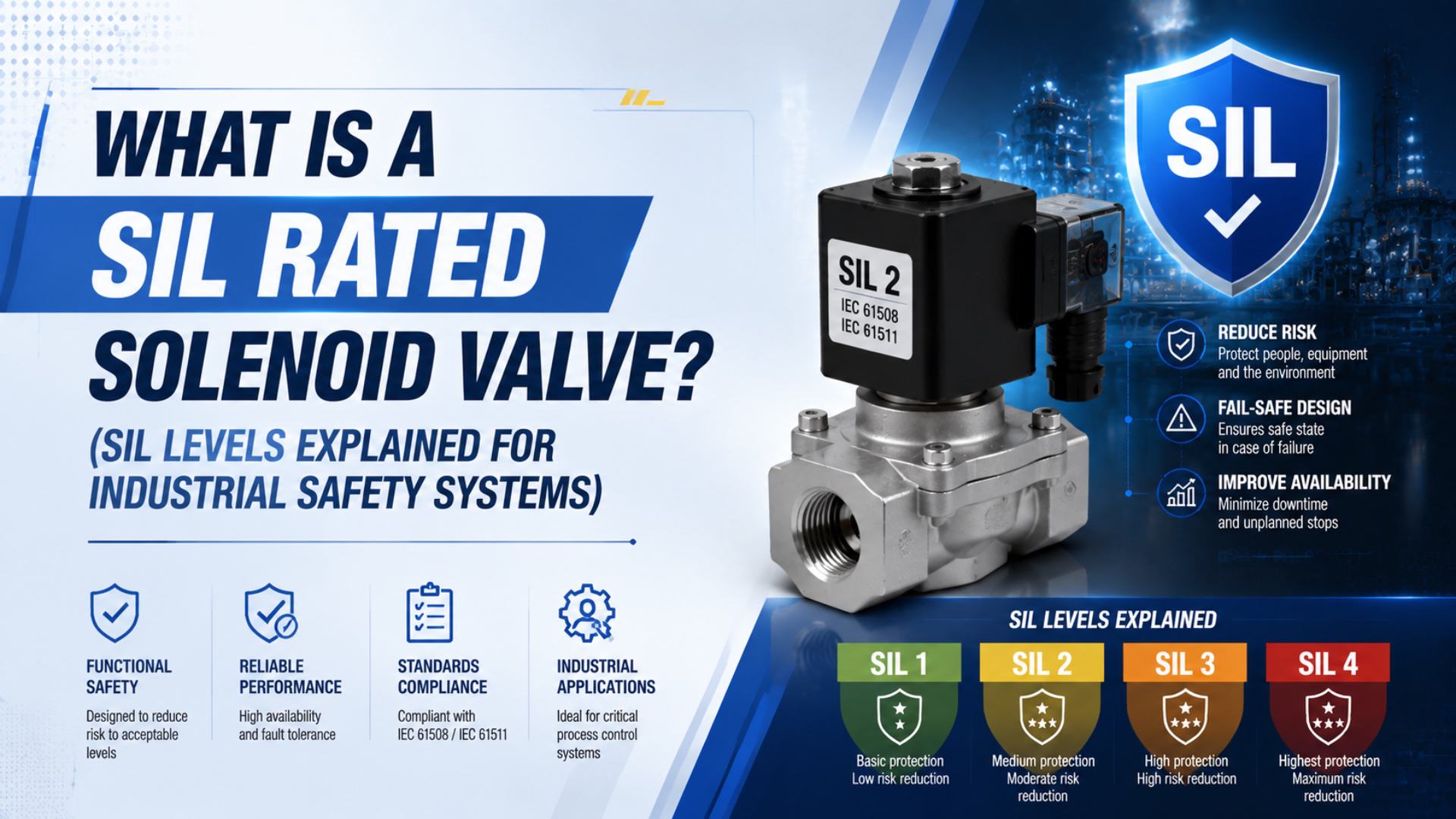
A SIL rated solenoid valve is a common purchasing term for a valve supported by functional-safety evidence for use within a Safety Instrumented Function, or SIF. Strictly speaking, the valve does not give the completed loop its SIL. IEC defines SIL as a property of a safety function, so the achieved level depends on the entire installed function and its lifecycle controls (IEC, 2022).
That distinction changes the buying question. Do not ask only, “Is this valve SIL 2 or SIL 3?” Ask what exact valve configuration was assessed, what safety action it performs, which failure data and restrictions apply, and how it contributes to the sensor-to-final-element calculation.
Key Takeaways
- IEC defines four SILs, but SIL belongs to the safety function, not an isolated valve.
- Check PFDavg or PFH, architectural constraints, systematic capability, and exact certificate scope together.
- Proof testing finds covered latent failures; it cannot correct the wrong fail state or system architecture.
The useful interpretation is evidence-based: a “SIL capable” solenoid valve may be suitable for a function up to a stated level under documented conditions. It is not a universal promise that every circuit using that valve achieves the same risk reduction.
What Does “SIL Rated Solenoid Valve” Actually Mean?
IEC 61508 defines four Safety Integrity Levels, from SIL 1 through SIL 4, and states that SIL is a property of a safety function (IEC, 2022). A valve certificate therefore supports a system calculation; it does not replace the calculation, integration rules, validation, maintenance, or management of change.
Manufacturers use several phrases that look similar but carry different implications:
| Supplier wording | Practical interpretation | What the buyer must verify |
|---|---|---|
| SIL capable | The assessed product may be used up to a stated SIL under defined restrictions | exact model, circuit function, systematic capability, architecture and safety manual |
| Suitable for use in SIL 2 or SIL 3 SIFs | The product contributes data and restrictions for a SIF at that target | the completed SIF still meets PFDavg/PFH, architecture and systematic requirements |
| IEC 61508 certified | A certificate covers a defined product scope and assessed capability | issuing body, certificate revision, covered options and validity of the supporting safety manual |
| Proven or justified by prior use | Application evidence is used instead of product certification | similar service, operating environment, failure history, change control and documented justification |
The exact certificate language matters. Emerson, for example, lists its ASCO Series 327 as “SIL capable,” while Bürkert says specified monostable Type 6519 functions can achieve SIL 2 depending on the safety-system architecture (Emerson ASCO Series 327, 2026; Bürkert Type 6519, 2026). Neither statement says every installation automatically achieves that level.
Where Does the Solenoid Valve Sit Inside a SIF?
A process-industry SIF normally spans three functional blocks: sensors, a logic solver and final elements. IEC 61511 states that the SIS includes all devices needed to carry out each SIF from the sensors to the final elements (IEC 61511-1, 2016). The solenoid valve is usually only one part of that final-element chain.
Consider an emergency shutdown that must close a process valve when pressure exceeds a trip point:
- A transmitter detects the process condition.
- The safety logic solver evaluates the trip.
- An output circuit changes power to the solenoid.
- The solenoid redirects or vents instrument air.
- The pneumatic actuator moves.
- The process valve reaches the defined safe position.
- Position feedback, when required, confirms the result.
The final-element boundary may also include wiring, terminals, power supplies, pilot-air filters, tubing, boosters, quick-exhaust devices, silencers and mechanical linkages. A clogged exhaust, low pilot pressure, incorrect spool function or seized actuator can defeat the shutdown even when the solenoid coil operates correctly.
For ordinary port and coil behavior, use the separate guide to how pneumatic solenoid valves control compressed air. A functional-safety review begins after that basic operation is understood.
SIL 1, SIL 2, SIL 3 and SIL 4 Target Failure Measures
The four SIL bands each cover one decade of target failure measure. For low-demand safety functions, IEC 61508 uses PFDavg; for high-demand or continuous functions, it uses PFH per hour. The ranges below apply to the complete safety function, not to a generic valve in isolation (IEC, 2022; ABB SIL Safety Manual, 2025).
| SIL | Low-demand PFDavg | Approximate risk-reduction-factor band | High-demand or continuous PFH |
|---|---|---|---|
| SIL 1 | at least 10⁻² and below 10⁻¹ | above 10 through 100 | at least 10⁻⁶ and below 10⁻⁵ per hour |
| SIL 2 | at least 10⁻³ and below 10⁻² | above 100 through 1,000 | at least 10⁻⁷ and below 10⁻⁶ per hour |
| SIL 3 | at least 10⁻⁴ and below 10⁻³ | above 1,000 through 10,000 | at least 10⁻⁸ and below 10⁻⁷ per hour |
| SIL 4 | at least 10⁻⁵ and below 10⁻⁴ | above 10,000 through 100,000 | at least 10⁻⁹ and below 10⁻⁸ per hour |
These are target bands, not industry labels. A chemical plant is not automatically SIL 2, and a power application is not automatically SIL 3. Hazard analysis and risk assessment define the required safety action and risk reduction. The design must then demonstrate that the complete function meets that requirement.
Do not allocate the entire PFDavg budget to the solenoid. Sensors, the logic solver and every element in the shutdown path contribute to the total. The project calculation should state the allocation method, failure rates, test intervals, repair assumptions, diagnostic coverage, common-cause assumptions and mission time.
Four Evidence Checks for Valve Suitability
A SIF must satisfy more than one numerical test. Current exida guidance identifies three IEC 61511 design requirements: PFDavg or PFH, architectural constraints and systematic capability; application suitability is an additional engineering check (exida, 2025). Passing only a PFDavg calculation is not enough.
1. What random hardware failure data apply?
Request dangerous detected and dangerous undetected failure rates, safe failure data where relevant, diagnostic assumptions, useful life and the source of the data. Confirm whether the values come from an FMEDA, field-return analysis, prior-use evidence or another documented method.
PFDavg is sensitive to more than the headline failure rate. Proof-test interval, proof-test coverage, diagnostics, repair time, voting architecture and common-cause assumptions can change the result. Use the safety manual’s conditions rather than copying a number from a marketing page.
2. What architectural constraint applies?
Hardware Fault Tolerance, or HFT, describes how many hardware faults can be tolerated before the safety function is lost. Safe Failure Fraction, or SFF, is used in one architectural assessment route. Neither metric is a standalone reliability score, and an SFF value cannot exceed 100%.
Adding a second solenoid does not automatically produce SIL 3. A 1oo2 arrangement may reduce dangerous failure probability for a shutdown action, but it can increase spurious trips and introduce shared pilot air, power, exhaust or contamination as common-cause paths. A 2oo2 arrangement behaves differently again. The safety requirements must define the intended voting and fault response.
3. What systematic capability is supported?
Systematic capability addresses design, specification, manufacturing, software where present, documentation and lifecycle controls that random failure calculations cannot capture. Verify the certificate’s systematic capability, product revision, restrictions and approved modification process.
4. Is the valve suitable for the actual service?
Functional-safety data do not override pressure, temperature, media, flow, electrical duty, ingress protection, hazardous-area or material limits. A qualified valve used outside its assessed operating conditions does not retain the assumptions behind its failure data.
The fastest certificate review is a four-way match: exact ordering code, exact safety action, exact operating envelope and exact maintenance assumptions. A family brochure that matches only the brand and series name leaves too much uncertainty for a SIF design record.
How Do Valve Function and De-Energized State Affect Safety?
Bürkert Type 6519 covers three directional functions, 3/2, 5/2 and 5/3, yet its SIL 2 statement is limited to specified monostable circuit functions C, D and H and remains architecture-dependent (Bürkert Type 6519, 2026). Port count or a NAMUR mounting pattern alone therefore cannot define the process safe state.
Start with the required process result:
- Must the process valve close, open, hold or vent?
- What must happen after loss of electrical power?
- What must happen after loss of instrument air?
- Can trapped pressure, a blocked silencer or a booster prevent movement?
- Is spring return available, and does it move the process valve in the required direction?
- Must the system detect failure to move or only command the action?
De-energize-to-trip is common because loss of power initiates the safety action, but it is not universally safer. Energize-to-trip may be justified for a different hazard. The decision belongs in the Safety Requirements Specification, together with response time, leakage limit, final position, reset behavior and diagnostic requirements.
A 3/2 normally closed valve may vent a spring-return actuator when de-energized. A 5/2 monostable valve may drive a double-acting actuator to a defined position. A 5/3 center condition can block, vent or pressurize ports, and those alternatives create very different fault behavior. The NAMUR solenoid valve guide explains the mechanical interface and circuit-function boundary.
Can a Standard Solenoid Valve Be Used in a Safety Instrumented Function?
IEC 61511 equipment qualification has two recognized paths in current exida guidance: use an IEC 61508 certified device for the required capability, or document prior-use justification (exida, 2025). A non-certified valve is not automatically prohibited, but unsupported familiarity or frequent testing is not prior-use evidence.
Prior-use justification must be application-specific. It should demonstrate sufficiently similar service conditions, operating profiles, environments, failure modes and organizational controls. It also needs credible operating history, failure reporting, configuration control and evidence that relevant systematic faults are acceptably controlled.
This path can be difficult when ordering codes changed, field failures were not recorded consistently, service conditions varied or returned products were analyzed only for warranty purposes. Certification often simplifies the evidence package, but even a certified device still needs application checking and a complete SIF calculation.
The purchasing decision should therefore distinguish three questions:
- Is the exact device qualified against systematic failure requirements?
- Does its random hardware data support the SIF calculation?
- Does the installed architecture satisfy the required constraints and safe action?
If any answer is missing, “SIL rated” on a quotation is not enough.
What Does Proof Testing Actually Maintain?
An ASCO solenoid proof-test supplement states that the test interval must be no longer than the interval used in the SIF reliability calculation. Its product-specific guidance recommends annual physical inspection and gives five years as the maximum inspection interval for that documented arrangement (Emerson, 2020). Those figures are not universal intervals for every valve.
Proof testing seeks dangerous undetected failures that automatic diagnostics did not reveal. A useful procedure defines:
- the covered valve configuration and safety action;
- how the SIF is bypassed or the process is protected during testing;
- electrical de-energization and pneumatic response checks;
- actuator and process-valve movement acceptance criteria;
- inspection for contamination, corrosion, moisture and blocked ports;
- proof-test coverage used in the PFDavg calculation;
- restoration, bypass removal and independent verification;
- failure recording and feedback into reliability data.
More frequent testing can reduce the time a covered latent failure remains hidden. It does not change a product’s systematic capability, correct a wrong architecture or prove a failure mode that the procedure never exercises. Partial-stroke testing can improve diagnostic coverage for some movement failures, but it does not replace a full test of the required safety action.
Maintenance changes also matter. Substituting a coil, seal kit, connector, lubricant or manual override may move the assembly outside the assessed configuration. Treat safety-related substitutions through the site’s management-of-change process and retain the certificate, safety manual and test procedure with the installed asset record.
Standards Boundary: IEC 61511, IEC 62061 and ISO 13849
IEC 61511 addresses process-industry SIS applications, while ISO 13849-1:2023 applies to safety-related control systems for machinery in high-demand and continuous modes, including pneumatic technology. ISO explicitly excludes low-demand operation from that edition’s scope (IEC 61511-1, 2016; ISO 13849-1, 2023).
Use the application boundary before selecting terminology:
| Application context | Typical primary framework | Typical integrity expression |
|---|---|---|
| Process shutdown, burner trip, HIPPS or emergency isolation | IEC 61511 within the IEC 61508 framework | SIL and PFDavg or PFH |
| Machine guard, hazardous-motion prevention or pneumatic energy discharge | ISO 13849-1 or IEC 62061, subject to applicable machine standards | PL or SIL, normally high-demand/continuous metrics |
| Explosive atmosphere | ATEX, IECEx or national HazLoc rules | equipment protection marking, not functional-safety integrity |
IEC 62061 specifies design, integration and validation requirements for machinery safety-related control systems and now covers non-electrical technologies within its scope (IEC 62061, 2026). The safety exhaust valve integration guide covers the machine-guarding side in more detail.
ATEX or IECEx approval answers a different question: whether the equipment is suitable for a defined explosive atmosphere. It does not prove that the valve will perform a specified shutdown function with the required integrity. The ATEX and HazLoc valve specification guide explains how to verify those markings separately.
What Should Be Included in a SIL Solenoid Valve RFQ?
A usable RFQ needs more than one requested SIL number. Since a SIF must meet PFDavg/PFH, architectural and systematic requirements, the buyer should request at least ten evidence fields before approving a substitution (exida, 2025). This prevents a broadly certified product family from being mistaken for an approved installed configuration.
| RFQ field | Required information |
|---|---|
| Safety function | open, close, vent, hold or isolate; trip trigger and safe state |
| Application standard | IEC 61511, IEC 62061, ISO 13849 or another applicable standard |
| Required integrity | target SIL or PL and demand mode |
| Exact hardware | manufacturer, series, complete ordering code, revision and accessories |
| Certificate scope | issuer, certificate number, covered model/options and systematic capability |
| Reliability data | failure rates, useful life, FMEDA or assessment-report reference |
| Architecture | 1oo1, 1oo2, 2oo2 or other arrangement; diagnostics and common-cause controls |
| Pneumatic conditions | supply pressure, minimum pilot pressure, flow, exhaust path and air quality |
| Electrical/environmental conditions | voltage, duty, temperature, ingress and hazardous-area requirements |
| Proof test | procedure, interval, coverage, acceptance limits and restoration controls |
Also request the current safety manual, not only the certificate. The manual should identify restrictions, failure behavior, installation requirements, proof-test procedures, diagnostic assumptions and any configuration that invalidates the assessed claim.
For replacements, compare assumptions before dimensions. A valve can match the NAMUR pattern, port size and coil voltage yet fail the safety review because its de-energized flow path, minimum pilot pressure, certificate scope or proof-test coverage differs from the approved design.
Final Selection Rule
Three tests must agree before a solenoid valve is accepted into a SIF: the exact device must be qualified, its failure data must fit the PFDavg or PFH calculation, and the installed architecture must deliver the specified safe action. A certificate can support all three reviews, but it cannot perform them for the designer or operator.
Record the evidence in the Safety Requirements Specification, verification calculation, device list, installation drawings and proof-test procedure. Then validate the complete installed action under realistic power, air, load and environmental conditions. That is what turns a capable component into part of a defensible safety function.
SIL-Rated Solenoid Valve FAQs: What Should Buyers Verify?
IEC defines four SILs, but buyers still need to verify three design requirements for the complete SIF: PFDavg or PFH, architectural constraints and systematic capability. These five questions close the most common gaps between a supplier’s “SIL capable” statement and an installed, validated safety function (IEC, 2022; exida, 2025).
Does IEC 61508 assign a SIL directly to a solenoid valve?
Not in the same sense as a completed safety function. IEC says SIL is a property of the safety function. A solenoid valve can have assessed systematic capability, failure data and architectural restrictions that make it suitable for use up to a stated SIL, but the complete SIF must still be calculated and validated.
What does “SIL 3 capable” mean on a valve datasheet?
It means the assessed valve may contribute to a SIL 3 safety function when the exact certified configuration, operating limits, systematic capability and architectural restrictions are satisfied. It does not mean a 1oo1 loop automatically achieves SIL 3, nor does it assign the complete PFDavg or PFH budget to that valve.
Can a non-certified solenoid valve be used in a SIF?
Potentially, but IEC 61511 requires a defensible qualification path. Current exida guidance identifies two routes: IEC 61508 certification or documented prior-use justification. Prior use needs comparable service, operating history, failure records and configuration control. Familiarity with a valve or frequent testing alone does not meet that evidence requirement.
Does proof testing increase a valve’s SIL rating?
No. Proof testing can reveal covered dangerous undetected failures and reduce their contribution to PFDavg when the documented interval and coverage are used in the calculation. It does not raise systematic capability, remove architectural constraints or test failure modes outside the procedure. The interval belongs to the complete SIF reliability plan.
Is ATEX or IECEx certification equivalent to SIL capability?
No. ATEX and IECEx address equipment use in specified explosive atmospheres, while IEC 61508 and IEC 61511 address functional safety. A valve may require both evidence sets, but one cannot replace the other. Verify the hazardous-area marking, functional-safety certificate and installed SIF design as separate acceptance tasks.
Sources and technical references
- IEC. Overview of IEC 61508 and Functional Safety. SIL definition, risk-reduction bands, safety-function boundary and lifecycle concepts. Retrieved July 27, 2026.
- IEC. IEC 61511-1:2016. Process-industry SIS specification, design, installation, operation and maintenance requirements. Retrieved July 27, 2026.
- IEC. IEC 62061:2021 with 2024 and 2026 amendments. Machinery safety-related control-system framework. Retrieved July 27, 2026.
- ISO. ISO 13849-1:2023. Machinery safety-related control systems, including pneumatic technology. Retrieved July 27, 2026.
- Bürkert. Type 6519 Solenoid Valve. Conditional SIL 2 statement for specified monostable circuit functions. Retrieved July 27, 2026.
- Emerson. ASCO Series 327. Product-specific IEC 61508 and SIL-capable classification. Retrieved July 27, 2026.
- Emerson. ASCO Solenoid Proof-Test Instructions. Product-specific proof-test purpose, interval and procedure. Retrieved July 27, 2026.
- exida. How a SIF Achieves Its SIL Target. PFDavg/PFH, architectural constraints and systematic capability. Retrieved July 27, 2026.
- exida. Prior-Use Justification. Equipment qualification through certification or prior-use evidence. Retrieved July 27, 2026.
- ABB. EL3000/EL3060 SIL Safety Manual. Reference PFDavg and PFH target bands and safety-integrity terminology. Retrieved July 27, 2026.