

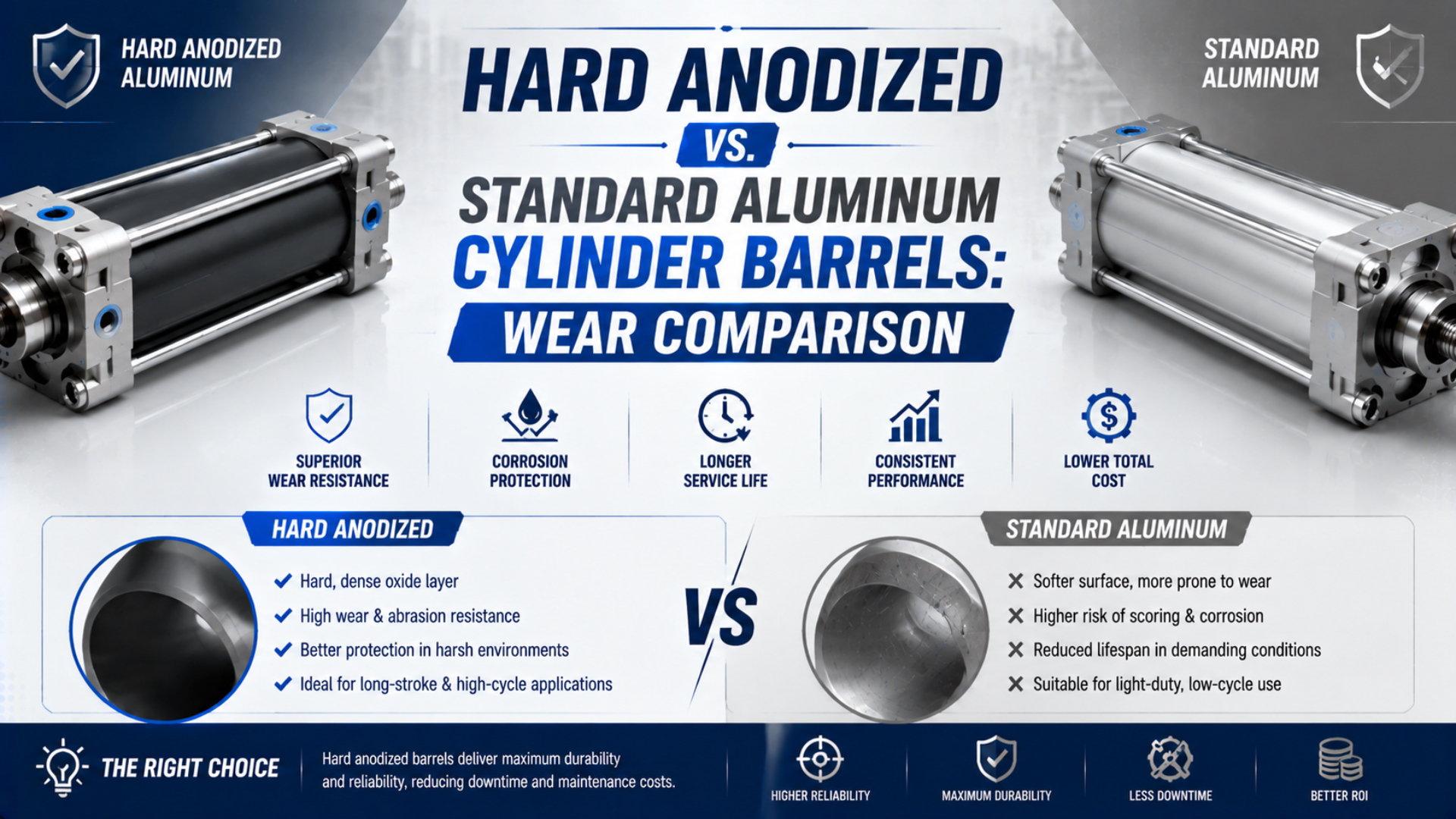
Hard anodizing usually provides more abrasion reserve than conventional protective anodizing, but the process label does not predict pneumatic-cylinder life. A valid comparison holds the alloy, seal, bore geometry, lubricant, contamination, pressure, speed, and alignment constant, then measures coating loss, surface change, leakage, friction, and completed cycles against declared failure limits.
ISO 8251:2018 defines three abrasion-test families for anodic oxide coatings: abrasive-wheel, abrasive-jet, and falling-sand tests. The first two can be applied to hard anodizing through ISO 10074, but none reproduces an entire pneumatic cylinder by itself (ISO 8251, 2018). Component-level life evidence still needs a controlled cylinder test.
Key Takeaways
- Compare named anodizing specifications, not “standard aluminum” against “hard aluminum.”
- Hardness, thickness, and roughness measure different properties; none alone proves bore life.
- Hold the complete seal-contact system constant during an A/B test.
- Normalize cost by completed cycles or travel, not calendar months.
First Define What “Standard Aluminum” Means
ISO uses separate standards for the baseline. ISO 7599:2018 covers protective anodic coatings; ISO 10074:2021 covers hard anodic oxidation. A valid comparison must name the alloy, temper, coating specification, sealing condition, treated surface, and finishing sequence (ISO 7599, 2018; ISO 10074, 2021).
“Standard aluminum barrel” can describe several different products:
- an untreated aluminum bore;
- a conventionally anodized bore;
- an anodized exterior with a differently finished interior;
- an anodized extrusion that is subsequently honed or polished;
- a tube with a liner or another functional coating.
Those surfaces cannot share one hardness, friction coefficient, or life rating. The aluminum alloy also matters. Alloying elements and heat-treatment condition affect how the oxide forms and how the substrate supports it. A hard oxide over a poorly supported or geometrically inaccurate bore is still a poor seal-running surface. MIL-PRF-8625F separates the two processes. It identifies Type II as conventional sulfuric-acid anodizing and Type III as hard anodic coating, with 0.002 in, about 50.8 µm, as the nominal Type III fallback when procurement documents do not specify another thickness. That default is not a pneumatic-cylinder optimum or life multiplier (DLA ASSIST, 2020).
For coating growth and final dimensions, use the separate hard-anodizing depth guide; the comparison here begins after both surfaces have been defined correctly.
What Does a Fair Cylinder-Barrel Wear Comparison Measure?
A coating test cannot reproduce a pneumatic cylinder. ISO 8251:2018 provides three abrasion methods, but the barrel adds a compliant polymer seal, changing pressure, lubricant, particles, bore geometry, and reciprocating motion. A fair comparison therefore needs standardized process-control evidence and a cylinder-level endurance test for the installed contact system (ISO 8251, 2018).
At the coating level, measure the property the drawing actually requires:
| Question | Appropriate evidence | What it cannot prove alone |
|---|---|---|
| Was the specified oxide produced? | Coating thickness and process certificate | Seal life |
| Does the coating resist a defined abrasive action? | Abrasive-wheel or abrasive-jet result | Performance with a specific piston seal |
| Is the coating hard enough at the test location? | Knoop or Vickers result with method and load | Abrasion rate or cylinder cycles |
| Is the finished bore suitable for the seal? | Diameter, roundness, straightness, texture, defect inspection | Long-term life under contamination |
| Does the complete cylinder remain functional? | Leakage, friction, motion, and endurance test | Performance outside the test boundary |
At the cylinder level, record initial, interval, and final measurements such as:
- breakaway pressure or force under a repeatable procedure;
- running friction at defined pressure and speed;
- internal leakage at fixed piston positions;
- bore diameter and form at mapped axial locations;
- Ra, Rz, profile features, and directional scratches;
- seal-lip mass, dimensions, or microscopy when the method is repeatable;
- coating exposure, scoring, polishing, cracking, or debris;
- completed cycles and cumulative travel at the first declared failure.
Do not rank surfaces with photographs alone. A dark barrel is not proof of Type III treatment, and a glossy wear track is not automatically damage. The track may represent benign running-in, lubricant redistribution, seal transfer, or loss of the functional surface. Measurements and a sectioned failure sample are stronger evidence.
Why Hardness Alone Cannot Predict Barrel Life
The AAC hardcoat guideline separates six application functions and assigns an abrasion test to its wear category. It also states that hardness cannot prove wear resistance. One HV or HRC value therefore cannot establish cylinder cycles, seal life, or maintenance savings (AAC Hard Anodic Oxide Guideline, 2024).
Hardness is an indentation result. ASTM E384 covers Knoop and Vickers testing under a named method, force, specimen preparation, and location, including error sources that matter for thin regions and small indents. Reporting “600 HV” without the load, cross-section preparation, number of indents, and location is incomplete (ASTM E384, 2022). Wear is a different response. It depends on contact pressure, sliding distance, particle hardness, particle entry, seal material, surface profile, lubricant, temperature, and substrate support. A hard but rough or cracked surface can damage a seal. A softer, well-finished surface in clean, aligned service can outlast a harder surface exposed to debris or edge loading.
Surface texture deserves its own acceptance method. Parker’s pneumatic-seal catalogue gives dynamic-surface examples of Ra 0.2 µm / Rz 1.0 µm for rubber and PTFE products and Ra 0.4 µm / Rz 1.6 µm for polyurethane products. These are product-family examples, not universal cylinder limits (Parker Pneumatic Seals, accessed 2026). The correct finish must come from the selected seal and measurement specification; the Ra versus Rz guide explains why one average cannot detect every scratch, peak, or waviness problem, while the barrel honing guide covers finishing sequence and post-process inspection.
Treat hardness as process evidence, abrasion as coating evidence, and endurance as system evidence rather than allowing a supplier to substitute one level for another.
A/B Wear Test Protocol for Cylinder Barrels
ISO 19973-3:2015 reports pneumatic-cylinder reliability in cycles or kilometres and defines test procedures, equipment, and threshold levels. It does not authorize a universal cycle claim for one coating. Your A/B program must declare the cylinder configuration, operating class, measurements, failure criteria, and treatment of repairs before testing begins (ISO 19973-3, 2015).
1. Lock the comparison boundary
Use the same cylinder design, bore, stroke, piston, seal batch, grease, ports, valve, tubing, mounting, and guidance. Compare barrels from a declared alloy and temper. If different alloys are unavoidable, describe the program as a surface-system comparison rather than a coating-only comparison.
2. Measure both groups before assembly
Map bore diameter, roundness, straightness, and texture at the same axial and circumferential locations. Measure coating thickness with a calibrated method and representative substrate. ISO 2360:2017 covers amplitude-sensitive eddy-current measurement for many anodic oxide coatings, but curvature, edge proximity, conductivity, and calibration still affect the result (ISO 2360, 2017). Record defects before the first stroke. Axial scratches, local thin areas, rack-contact marks, chipped edges, debris, and out-of-tolerance bores can otherwise be misclassified as test wear.
3. Control the duty
Record supply and chamber pressure, speed, stroke, cycle profile, temperature, air quality, lubrication condition, load, and alignment. Control end impact. If the goal is contamination resistance, introduce a defined contaminant separately instead of allowing uncontrolled shop dust to determine the result.
Side loading must remain measured and repeatable. It changes local seal pressure and guide reaction, so an uncontrolled offset can dominate the coating comparison. The cylinder side-loading guide explains why harder bore material cannot correct misalignment.
4. Set interval checks and stop limits
Choose inspection intervals before the run. A useful program can track leakage, breakaway behavior, running friction, temperature, surface condition, and particle generation without dismantling every sample at every interval.
Define failure in measurable terms. Examples include leakage above a declared limit, inability to complete the stroke at the specified pressure, friction outside the approved band, coating breakthrough at a functional location, or bore geometry outside tolerance. “Looks worn” is not an acceptance criterion.
5. Compare distributions, not one best sample
One cylinder per surface cannot describe manufacturing variation. Use an approved sample plan, preserve all results, and report censored units that have not yet failed. Do not delete early failures as “assembly errors” unless a documented investigation proves they are outside the test boundary.
Which Applications Actually Favor Hard Anodizing?
One product family shows the boundary. Parker documents internal and external anodizing on C41 aluminum barrels from 32 to 125 mm bore for wear and sliding properties, but that model-specific construction does not establish a universal process or service-life advantage for every pneumatic cylinder (Parker C41, accessed 2026).
Hard anodizing is a strong candidate when:
- a controlled baseline shows abrasive wear of the bore rather than misalignment damage;
- the seal supplier approves the final surface condition;
- debris cannot be eliminated completely and the design includes appropriate exclusion;
- high cumulative travel makes measurable coating wear a life-limiting mechanism;
- the application needs a defined abrasion-resistant surface and the supplier can verify it;
- the added thickness, edge condition, and finishing sequence fit the dimensional design.
Conventional protective anodizing may be sufficient when:
- the cylinder runs in clean, aligned service with low cumulative travel;
- the selected product already has documented life evidence for the duty;
- bore wear is not the observed failure mode;
- replacement cost is low and downtime is planned;
- a hardcoat option lacks defined finish, dimensional, or test requirements.
Fix the failure first. One-sided seal wear suggests alignment or guide loading. Deep axial scoring suggests particle entry or assembly damage. Local edge failure may indicate geometry, masking, or handling. Sticky motion can come from grease aging, seal compound, pressure control, or bore texture rather than coating loss.
The decision boundary is not “high cycle versus low cycle.” It is whether coating wear remains the limiting mechanism after alignment, contamination, lubrication, seal selection, and finished geometry are controlled.
How Do You Compare Total Cost Without Inventing a Lifetime Multiplier?
Calendar months hide duty. ISO 19973-3 expresses pneumatic-cylinder life in cycles or kilometres, so cost should use the same denominator: purchase, maintenance, downtime, and quality loss per completed cycle or travel unit. A slow machine and a high-speed machine are not equivalent merely because both ran for one year (ISO 19973-3, 2015).
A practical normalized-cost relationship is:
Here, is cost per completed cycle or travel unit. The numerator includes the costs recorded inside the same evaluation boundary, and is successful production duty before the declared end point.
Use actual records for each term:
| Cost input | Minimum evidence |
|---|---|
| Purchase | Quoted barrel or complete-cylinder price for the exact specification |
| Planned maintenance | Labor time, seal kit, grease, inspection, and scheduled machine access |
| Unplanned downtime | Recorded event duration and approved cost model |
| Quality loss | Scrap, rework, or rejected output linked to the cylinder failure |
| Completed duty | Counter data, PLC records, or travel calculation with a documented boundary |
| Residual value | Remaining qualified life or reusable components, if the policy recognizes them |
Compare at least one complete maintenance horizon. Do not assume that a harder coating automatically reduces seal changes, and do not assign downtime savings before a matched test or fleet record shows a difference. If the hard-anodized barrel survives while the seal, guide, or valve remains the limiting component, its additional wear reserve may not reduce system cost. Use the cycle-count and seal-lip wear guide to separate cumulative duty from seal material loss, and apply the leakage-path analysis to scored bores before attributing every leak to surface treatment.
RFQ and Inspection Requirements for a Verifiable Comparison
Start with function. The AAC hardcoat guideline defines six application functions and requires thickness checks for all six, while assigning other tests by duty. A cylinder RFQ should then name the process, finished dimensions, surface condition, and acceptance evidence (AAC Hard Anodic Oxide Guideline, 2024).
Include these items in the drawing or purchase specification:
- Cylinder series, bore, stroke range, drawing revision, and affected barrel surfaces.
- Aluminum alloy, temper, extrusion or tube specification, and permitted substitutions.
- Conventional or hard anodizing standard, type, class, nominal thickness, and tolerance.
- Sealed or unsealed condition, accepted method, masking, and rack-contact restrictions.
- Final bore diameter, roundness, straightness, taper, and measurement locations.
- Surface-texture parameters, filter settings, evaluation length, lay direction, and prohibited defects.
- Seal compound, lubricant, intended pressure, speed, temperature, and air-quality boundary.
- Thickness measurement method, calibration reference, sampling plan, and report format.
- Required abrasion, corrosion, adhesion, or hardness test with acceptance limits.
- Cylinder-level leakage, motion, endurance, and failure criteria.
- Initial sample approval and supplier change-notification requirements.
- Disposition rules for low thickness, rework, stripping, and dimensional nonconformance.
ISO 2360 describes nondestructive eddy-current measurement for many oxide coatings on aluminum, but a long bore needs defined access and sampling locations; a flat process coupon can support process control without proving coating distribution, texture, or geometry throughout the functional bore. Color proves nothing by itself. Hard anodized coatings vary with alloy, thickness, process, and dye. Use the drawing, certificate, calibrated thickness readings, and a destructive cross-section when justified. For wear qualification, connect that process report to the exact cylinders used in the A/B test.
A useful supplier comparison is traceable in both directions: each endurance result points back to a barrel lot and inspection record, while each coating report points forward to the assembled cylinder and test result.
The Selection Rule
Use two evidence levels. ISO 10074:2021 specifies hard-anodic-coating requirements and tests, while ISO 19973-3:2015 addresses cylinder reliability. Verify the coating first and the assembled cylinder second; neither standard supports a universal two-times or five-times service-life claim (ISO 10074, 2021; ISO 19973-3, 2015).
Choose hard anodizing when a defined abrasion problem, compatible seal surface, dimensional design, and controlled evidence justify it; choose conventional anodizing when the installed duty is already met and coating wear is not the limiting failure mode.
Reject the marketing multiplier. Buy a specified surface, an inspection record, and performance evidence tied to your duty.
Hard Anodized Cylinder Barrel FAQs
One default needs context. MIL-PRF-8625F uses 0.002 in, about 50.8 µm, as the nominal Type III fallback when procurement documents do not specify another thickness. These five answers connect that number to alloy, finish, seal, geometry, and test evidence (DLA ASSIST, 2020).
Does hard anodizing make a cylinder barrel last five times longer?
No universal multiplier is defensible. Hard anodizing can add abrasion reserve, but cylinder life also depends on bore finish, seal compound, lubrication, contamination, alignment, pressure, speed, and failure criteria. Use matched endurance data or field records from the same configuration before assigning cycles, years, or savings.
Is a higher Vickers hardness always better for piston seals?
No, it isn’t. The AAC states that hardness results cannot prove wear resistance. A hard surface can still be rough, cracked, poorly supported, or incompatible with the seal. Specify the method and load when needed, then verify abrasion, final texture, geometry, leakage, and endurance separately.
Can I identify a hard-anodized barrel by its dark color?
No, you can’t. Color varies with alloy, oxide thickness, electrolyte, dye, sealing, and process conditions. Confirm the drawing, review the supplier certificate, and measure thickness with an applicable calibrated method. Appearance can support inspection without establishing coating type or wear performance.
Should a hard-anodized bore be honed after anodizing?
Only with process control. Post-treatment finishing can improve texture or geometry, but excessive material removal reduces the functional coating. The released process must account for removed oxide and specify the complete sequence, final thickness, bore dimensions, texture limits, cleanliness, and inspection locations.
What evidence should a supplier provide for a wear comparison?
Request alloy and process traceability, coating thickness maps, final bore geometry and texture, applicable abrasion or hardness results, seal and lubricant identification, cylinder-level test conditions, interval measurements, declared failure criteria, and all sample results. A generic certificate or one photograph cannot establish comparative barrel life.
Sources and technical references
- ISO 10074:2021, hard anodic oxidation coatings on aluminium and its alloys, retrieved 2026-07-27.
- ISO 7599:2018, decorative and protective anodic oxidation coatings, retrieved 2026-07-27.
- ISO 8251:2018, abrasion resistance of anodic oxidation coatings, retrieved 2026-07-27.
- ISO 19973-3:2015, reliability testing for pneumatic cylinders with piston rods, retrieved 2026-07-27.
- ISO 2360:2017, eddy-current coating-thickness measurement, retrieved 2026-07-27.
- MIL-PRF-8625F Amendment 2, anodic coatings for aluminum, retrieved 2026-07-27.
- AAC application guideline for hard anodic oxide finishes, retrieved 2026-07-27.
- ASTM E384-22, microindentation hardness of materials, retrieved 2026-07-27.
- Parker C41 pneumatic cylinders, retrieved 2026-07-27.
- Parker Pneumatic Seals catalogue, retrieved 2026-07-27.