

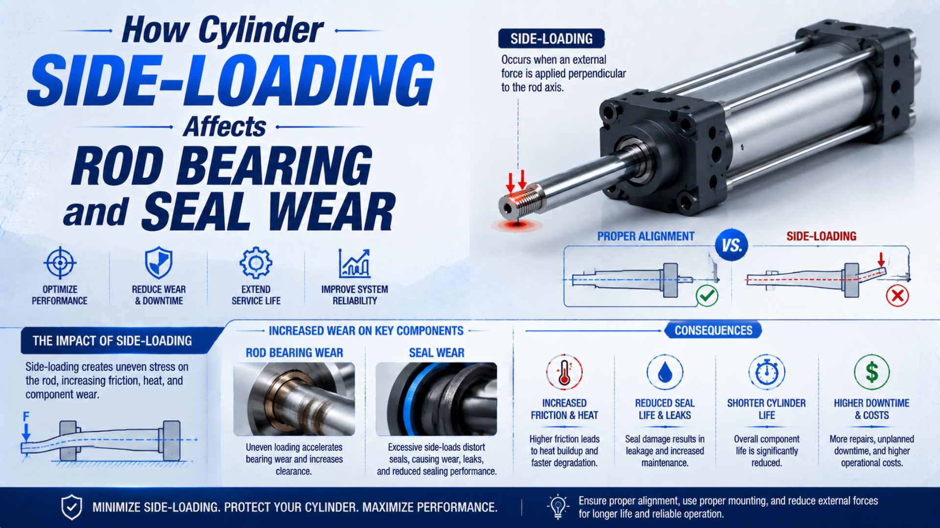
Cylinder side-loading is a force component acting across the intended stroke axis. It first biases the piston rod against one sector of the rod bearing or guide bushing. As clearance and surface damage develop, the rod no longer passes concentrically through the pressure seal, so the seal lip sees uneven contact, friction, and wear. That sequence explains why replacing a leaking seal can produce only a short-lived repair. The useful evidence is directional: the installed load direction, bearing contact sector, rod scoring, seal-lip wear, and stroke position where friction rises should agree. If they don’t, contamination, temperature, material compatibility, internal leakage, or assembly damage may be the stronger cause.
Key Takeaways
- Side force and offset create a bending moment; axial thrust percentage is not a side-load rating.
- One-sided bearing polish, rod scoring, and seal-lip wear should be mapped in their installed clock positions.
- Compare unloaded and loaded alignment at retracted, mid-stroke, and extended positions.
- Correct the load path before fitting another seal kit.
Readers who need the broader definition and machine-level consequences can start with what side loading means on a linear actuator. This guide stays with the mechanical path from transverse load to rod-bearing and seal wear.
What Mechanical Path Turns Side Load Into Seal Wear?
One Festo DFM-25-80 guided drive lists a maximum transverse force of 810.7 N and a stroke-dependent permissible of 4.17 N·m, even though its maximum static is 27.56 N·m (Festo DFM-25-80 Technical Data, accessed 2026). Those separate values show why force, moment, stroke, and operating condition cannot be collapsed into one percentage of cylinder thrust.
Start with the load path. A perpendicular force applied directly at the rod connection pushes the rod toward one side of the head bearing. When that force acts at a distance from the effective support, it also creates a bending moment:
Here, is the bending moment in N·m, is the force component perpendicular to the stroke axis in newtons, and is the perpendicular offset in meters. This relationship identifies the applied moment only. It does not calculate bearing contact pressure or prove that a selected cylinder can carry the load.
As the rod extends, the moment usually becomes more consequential because the unsupported geometry changes. A machine may therefore move freely near retraction but develop friction, stick-slip, or leakage closer to full extension. Gravity on an overhung tool can create this pattern even when the guide and cylinder look aligned at the home position.
Load transfer follows this sequence:
- A transverse force or offset moment deflects the rod or constrains it away from the cylinder axis.
- The rod reacts against one sector of the guide bushing instead of distributing contact around the bearing length.
- Local contact pressure and friction rise at that sector; the opposite side loses support.
- Polishing, transfer material, scoring, or clearance growth lets the rod move farther off axis.
- The rod passes through the pressure seal eccentrically, increasing lip compression on one side and reducing it on the other.
- Leakage appears after the supporting geometry and surface condition have already deteriorated.
The first visible air leak is often late evidence. The bearing contact map and rod surface can preserve the earlier stages, which is why they should be inspected before the gland is cleaned or the parts are mixed on a workbench.
This is also why increasing bore size is not a reliable correction. A larger bore raises axial force, but it doesn’t automatically improve the installed guide geometry or remove the offset. Review axial force and guidance as separate engineering tasks.
Why Does Bearing Edge Contact Appear Before Seal Leakage?
Parker instructs technicians to check piston-rod alignment in 2 positions, extended and retracted, and warns that improper alignment causes excessive rod-gland or cylinder-bore wear (Parker Pneumatic Cylinder Safety Guide, accessed 2026). A single home-position check can therefore miss a load path that changes through the stroke.
A rod bearing is a support surface, not a self-aligning rail. Under an acceptable load, its length and clearance guide the rod while leaving enough running clearance for the specified lubrication and temperature range. Under a biased load, contact migrates toward an edge or a short sector. The same total transverse force acting over a smaller effective contact area produces more local stress.
Several conditions can concentrate that contact:
| Condition | How the bearing is loaded | Expected stroke dependence |
|---|---|---|
| Overhung tool weight | Gravity creates transverse force and an offset moment | Usually worse as support geometry becomes less favourable |
| Cylinder and external rail not parallel | The connection forces the rod to follow a conflicting axis | Binding may peak near one end or reverse direction |
| Rigid coupling with assembly offset | The rod is pulled sideways into the machine connection | Can be present throughout the stroke |
| Frame or bracket deflection | Alignment changes only under production load | May disappear during an unloaded maintenance check |
| Pivot mount constrained from rotating | Intended angular motion becomes rod bending | Often changes as the mechanism moves through its arc |
| Bent or deeply scored rod | The damaged rod creates cyclic radial displacement | Repeats at the same rod rotational position |
What happens next? The bearing can polish on the loaded side, wear into an oval or tapered clearance, or transfer debris onto the rod. A hard particle trapped in that loaded interface can draw a longitudinal line along the rod. That line then passes under the wiper and pressure seal on every cycle.
Seal compliance may retain air while accommodating a small positional error. That temporary compliance is not proof that alignment is acceptable. Once rod movement, roughness, or lip distortion exceeds what the sealing system can accommodate, external leakage begins. By then, a seal-only replacement may leave the original bearing and rod damage untouched.
Component functions are compared in the companion guide on how rod bearings prevent repeat rod-seal failures.
Clock-Position Wear Patterns Reveal the Load Direction
Parker’s troubleshooting guidance separates at least 3 rod-leak branches: a worn or damaged seal, excessive gland clearance, and seal-material deterioration (Parker Pneumatic Cylinder Safety Guide, accessed 2026). Mapping each mark in its installed orientation helps distinguish a directional load path from these competing causes.
Before disassembly, mark the top of the cylinder head, rod, gland or cartridge, and mounting bracket. Use a simple clock reference when viewed from the rod end: 12 o’clock is machine-up, 3 o’clock is right, and so on. Photograph leakage and deposits before wiping them away. If the seal or bushing can rotate during removal, add matching witness marks first. Don’t rotate loose parts on the bench and then try to infer direction from memory. Preserve orientation as evidence. This discipline turns “the seal wore out again” into a testable mechanical hypothesis.
Then compare the evidence:
| Observation in installed orientation | Side-load interpretation | Competing explanation to check |
|---|---|---|
| Bearing polished mainly at 6 o’clock | Downward reaction, often from overhung weight | Abrasive debris settled in the lower sector |
| Seal lip worn at the same clock position as bearing polish | Rod is passing eccentrically through the seal | Incorrect seal installation or local gland damage |
| Long rod score aligned with the loaded bearing sector | Repeated hard contact or trapped debris in the biased interface | External chip damage before the rod entered the wiper |
| Opposing marks on bearing and piston guidance | Rod-piston assembly may be reacting as a beam | Bore damage, loose piston, or assembly error |
| Wear direction reverses between stroke ends | Cylinder axis and machine guide may cross | Flexible frame or bracket movement under load |
| Seal wear is uniform around the circumference | Side loading is not the leading explanation | Age, material, lubrication, temperature, pressure, or contamination |
Agreement matters more than any single mark. A credible side-load diagnosis connects at least three observations: the external reaction direction, the bearing or rod contact sector, and the stroke position where friction or leakage changes. If these observations contradict one another, keep the fault tree open.
How Should Side Loading Be Measured on the Machine?
ISO 15552 covers mounting dimensions for pneumatic cylinders with bores from 32 mm through 320 mm and a maximum rated pressure of 1,000 kPa, but it does not define one universal side-load capacity (ISO 15552:2018, confirmed 2025). Measurement limits must come from the exact cylinder, guide, joint, and machine documentation.
First make the machine safe. Follow the site’s energy-control procedure, isolate pneumatic and other energy sources, secure gravity loads, exhaust trapped pressure, and verify the safe state before loosening mounts or touching the mechanism. Observation during controlled operation and hands-on measurement after isolation are separate activities.
Use the same reference surfaces and instruments at every position. A useful worksheet records:
| Test point | Unloaded result | Representative-load result | What the difference can show |
|---|---|---|---|
| Rod retracted | Baseline centerline, free motion, and clearance | Mount or coupling movement near home | Fixed assembly offset or home-end constraint |
| Mid-stroke | Intermediate alignment and guide resistance | Frame movement or rail parallelism error | A crossing axis or structural deflection |
| Rod extended | Maximum exposed geometry and tool offset | Highest gravity moment or bracket deflection | Extension-sensitive side loading |
Repeat the inspection in the same sequence:
- Record cylinder model, bore, stroke, mount, rod-end joint, guide model, payload, center-of-gravity offsets, speed, cycle rate, and the stroke position where symptoms appear.
- Establish datums on the cylinder body and machine guide. Measure parallelism or relative displacement at retracted, mid-stroke, and extended positions.
- Repeat under a representative load when the approved procedure permits. Record temperature because the frame, tool, and guide can move after warm-up.
- Measure rod runout or straightness using the cylinder manufacturer’s support method. Don’t invent a universal rejection value; fixture span and measurement method affect the result.
- Check bushing clearance, rod diameter and surface, seal groove condition, mount movement, fastener condition, and guide play against model-specific service limits.
- Compare actual transverse forces and moments with every applicable catalog axis and operating condition. Include gravity, acceleration, tool contact, hose drag, and hard-stop reactions.
Moment calculations are useful only when the force and offset are real. Measure the load’s center of gravity from the relevant guide or support reference, not from a convenient edge of the tool plate. Dynamic contact forces may require test data or a machine-dynamics review; static weight alone will not represent a fast pick-and-place impact.
A wider retrofit workflow, including guide-axis and mounting choices, appears in how to mitigate side-load issues in linear cylinder applications. Mount behavior is covered separately in which cylinder mounting type maximizes load capacity.
How Can You Separate Side Loading From Other Seal Failures?
Parker’s troubleshooting guide identifies at least 4 alternatives to a simple side-load diagnosis: rough rod damage, excessive gland clearance, lubricant or fluid incompatibility, and temperature-related loss of seal elasticity (Parker Pneumatic Cylinder Safety Guide, accessed 2026). Directional wear is evidence, but it isn’t sufficient by itself.
Use a fault tree rather than one symptom-to-one-cause matching:
| Evidence combination | Leading branch | Confirmation needed |
|---|---|---|
| One-sided bearing polish, matching rod score, worse near extension | External transverse force or moment | Load direction, offset, guide alignment, configured moment limit |
| One-sided wear with no external load and repeatable rod wobble | Bent rod, loose assembly, or damaged head | Runout, piston connection, bushing bore, rod surface |
| Random scratches with dirt at the wiper | External contamination | Wiper condition, guarding, rod exposure, particle source |
| Uniform hard or cracked lip | Temperature or material incompatibility | Actual temperature, seal compound, lubricant and chemical exposure |
| Uniform wear with high cycle count and acceptable alignment | Service wear or lubrication condition | Manufacturer maintenance data and surface finish |
| Leakage only after a seal replacement | Installation damage, wrong kit, gland damage, or unresolved load path | Part number, lip orientation, assembly tool, groove and rod inspection |
| Apparent cylinder drift without rod-end leakage | Internal piston seal, valve, or circuit leakage | Approved isolation and leakage-localization test |
Side-loading becomes the leading diagnosis when several directional observations agree and change predictably with load or stroke. Contamination tends to create scratches related to particle travel, while chemical or thermal damage often changes the seal material more uniformly. A bent rod may mimic side load but produces a repeatable displacement tied to rod rotation or position. However, pressure can obscure the diagnosis. Raising pressure may push through friction and make motion appear smoother for a short time, but it increases axial force without correcting crossed axes or bearing edge contact. Treat added pressure as a changed test condition, not as proof of a repair.
In our experience, the most revealing comparison is often simple: record breakaway behavior with the tool unloaded, then repeat at the same three stroke positions under a representative load. A large change under load points back toward the external structure, guide, offset, or mounting rather than the seal alone.
When Should the Load Path Be Redesigned?
Festo describes guided drives with 2 guide rods and strokes up to 400 mm, but it still publishes transverse-force and moment limits for configured models (Festo Guided Drives White Paper, 2018). “Guided” and “rodless” describe architectures; neither word means unlimited load capacity.
Redesign is justified when the existing arrangement cannot keep the cylinder on its intended axis within documented limits. Typical triggers include a payload carried directly by an extended rod, an overhung center of gravity, crossed guide and cylinder datums, hard-stop reactions through the rod, insufficient moment data, or repeat bearing and seal damage after correct service work.
Choose the correction by the failed function:
| Failed function | Appropriate correction | Verification requirement |
|---|---|---|
| Machine load lacks linear support | Add a separate linear guide or supported carriage | Check force and moments in all axes over the full stroke |
| Tool must resist rotation | Use a guided cylinder, slide, or anti-rotation mechanism | Verify torque, transverse force, speed, and center-of-gravity limits |
| Small connection offset constrains the rod | Use a manufacturer-approved floating joint | Verify articulation without asking the joint to carry the payload |
| Pivoting mechanism binds | Match pivot mounts and joint axes to the motion arc | Confirm free angular travel at both stroke ends |
| Frame deflects under load | Increase structural stiffness or move the reaction path | Repeat loaded alignment after thermal stabilization |
| Rod or head is already damaged | Replace the damaged components or cylinder after root-cause correction | Inspect the complete load path before commissioning |
A rodless actuator may shorten installation length and place the payload on a carriage, but some designs require a separate guide while others integrate one. Selection must use the exact carriage-load and moment diagrams. A guided rod cylinder also has configured limits. Compare architecture only after defining the force vector, center-of-gravity offsets, stroke, speed, acceleration, duty, mounting direction, and environment. How should commissioning prove the correction? Start with mechanical freedom and alignment, then follow the approved low-energy commissioning procedure. Progress to representative load and speed while recording pressure during motion, stroke time, temperature, leakage, repeatability, and any change in breakaway behavior. Reinspect witness marks and fasteners after the defined run-in period.
Selection details for guided architectures are in the compact guide-cylinder selection guide. If a rodless layout is under consideration, use the rodless cylinder mounting guide to keep carriage guidance and mounting parallelism in scope.
Directional Evidence Makes the Repair Verifiable
Parker requires alignment checks at 2 stroke positions, extended and retracted, because an installation can be aligned at one end yet load the rod gland or bore at the other (Parker Pneumatic Cylinder Safety Guide, accessed 2026). A defensible repair therefore records geometry and symptoms across the stroke, not just after the leak stops.
Successful correction should change the evidence. The loaded and unloaded centerline measurements should converge, binding should no longer grow toward one stroke position, and new directional marks should not appear during the agreed run-in inspection. Record the configured load limits, measurements, parts replaced, commissioning conditions, and follow-up result so the next technician can distinguish recurrence from a different failure mode.
Repeatability is the proof.
Cylinder Side-Loading FAQs
For one Festo DFM-25-80 model, the published maximum transverse force is 810.7 N, maximum static is 27.56 N·m, and stroke-dependent permissible is 4.17 N·m (Festo DFM-25-80 Technical Data, accessed 2026). These different numbers explain why each FAQ answer starts with configured data and physical evidence rather than a universal rule.
Can side load be specified as a percentage of cylinder thrust?
Axial thrust cannot serve as a side-load percentage. It comes from pressure acting on piston area, while transverse loading depends on force direction, offset, stroke, mounting, guidance, and dynamics. Festo publishes force and moment values separately. Use the exact manufacturer’s curves and axes instead of assuming that 10%, 25%, or another fraction is acceptable.
Why does a new rod seal start leaking again?
A new seal can leak again when the bearing clearance, rod scoring, misalignment, contamination source, or external side load was never corrected. Parker links rod-seal leakage with damaged seals, rough rods, and excessive gland clearance. Preserve the old seal’s clock position, inspect the rod and bearing, then verify alignment through the full loaded stroke before reassembly.
Does one-sided seal wear prove side loading?
One-sided wear supports a directional-load hypothesis but does not prove it. Installation damage, a bent rod, local gland damage, or concentrated contamination can look similar. Confirm that seal wear, bearing contact, rod scoring, external reaction direction, and the stroke-dependent symptom agree. Otherwise, check material, temperature, lubrication, contamination, and internal leakage branches.
Can a floating joint replace an external guide?
A floating joint accommodates limited connection error, but it isn’t a linear bearing and should not be assumed to carry the payload or overturning moment. Keep it within its articulation and load ratings. The machine guide or guided actuator must still carry the documented transverse forces and moments throughout the complete stroke.
Are rodless or guided cylinders immune to side-load wear?
Rodless and guided architectures are not immune. They can place the load on a carriage or integrated guide instead of a conventional piston rod, but their bearings still have force, moment, speed, stroke, and life limits. Festo’s DFM data lists separate , , , , and values. Verify the configured model.
Sources and technical references
- Festo DFM-25-80-P-A-GF technical data, transverse-force, moment, speed, stroke, and configuration limits; accessed 2026-07-19.
- Festo, Considerations for Choosing Pneumatic Guided Drives and Slides, guide architecture and application forces; 2018, accessed 2026-07-19.
- Parker, OSP-P Pneumatic Rodless Cylinders and Linear Guides Catalog, cylinder safety, alignment, gland wear, seal leakage, and troubleshooting; accessed 2026-07-19.
- ISO 15552:2018, Pneumatic fluid power cylinders, dimensional interchangeability scope for 32-320 mm bores; confirmed 2025, accessed 2026-07-19.