

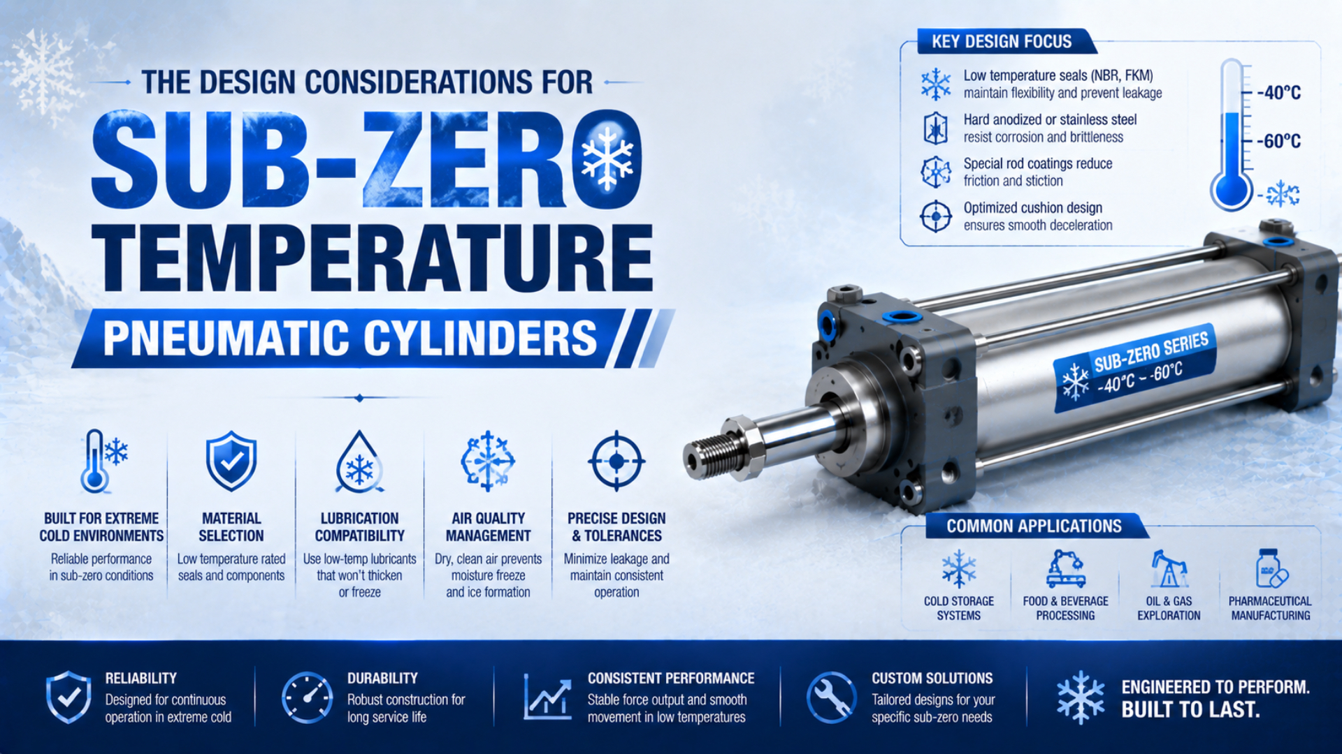
A sub-zero pneumatic cylinder should be selected as a complete, documented configuration, not as a standard cylinder with a cold-resistant seal substituted later. The real specification includes ambient and compressed-air temperature, seals, grease, cushioning, sensing, wipers, mounting, air quality, speed, pressure, and the cold-start acceptance test.
The difference is visible in current catalogs. SMC’s -XB7 cold-resistant option is rated from -40°C to 70°C, but it changes the seal material and grease and excludes several standard arrangements. Festo and Parker also offer -40°C cylinder variants, with different option combinations and accessory limitations (SMC; Festo; Parker).
Key Takeaways
- A
-40°Crating applies only to the documented model and option combination.- SMC’s -XB7 specification changes seals and grease and can exclude switches, cushions, and airline lubrication.
- Keep pressure dew point below the coldest compressed-air location, then prove performance with a cold-soak start test.
What Temperature Must the Complete Cylinder Survive?
SMC rates -XB7 from -40°C to 70°C, while Festo lists -40°C to 80°C for CRDSNU-TT (SMC; Festo). These model-specific ambient ranges do not permit every pneumatic cylinder to operate at -40°C.
Start by separating the temperatures that are often compressed into one phrase:
| Temperature input | What it means | Where to verify it |
|---|---|---|
| Minimum ambient | Coldest air surrounding the installed component | Cylinder body, valve island, sensor, tube, fittings, and enclosure |
| Minimum media | Coldest compressed air entering the cylinder | Point-of-use temperature measurement and component datasheet |
| Cold-soak temperature | Temperature after the longest expected shutdown | Logged body and accessory temperature before the first command |
| Continuous operating temperature | Temperature reached during normal cycling | Temperature trend after production stabilizes |
| Short transient | Local cooling during expansion, exhaust, or rapid cycling | Test data at the cylinder ports and exhaust |
The site weather minimum alone is not sufficient. A cylinder inside a freezer may remain at a stable temperature, while an outdoor actuator can experience wind, radiative cooling, freezing rain, and long idle periods. Compressed air can also reach a different temperature from the surrounding body.
Define the lowest credible value for each condition. Then add a project margin that accounts for sensor uncertainty, local cold spots, startup transients, and the consequence of a missed stroke. The margin should be stated in the specification, not hidden inside an informal label such as “winterized.”
A sub-zero rated pneumatic cylinder is an exact ordered configuration whose documented limits cover the specified ambient, media, startup, pressure, speed, and duty conditions. If the datasheet covers only the cylinder body, the installed assembly is not yet qualified.
Verify the Complete Low-Temperature Configuration
SMC’s -XB7 catalog specifies low-temperature nitrile seals and cold-resistant grease, but also states that an auto switch is not mountable, an air-cushion version is unavailable, and pneumatic-system lubrication should not be used (SMC). One temperature number therefore cannot describe the whole configuration.
From our analysis of current SMC, Festo, and Parker option tables, the shared -40°C headline does not represent a shared configuration. Treat the complete ordering code as the temperature-rated item. A base series may have dozens of combinations, yet the low-temperature suffix can remove some of them. Festo, for example, shows compatibility restrictions between its CRDSNU-TT option and certain wiper, piston-rod, end-cap, heat-resistant, and hazardous-area variants (Festo).
Build a configuration register before issuing the purchase order:
| Item | Evidence to request | Common oversight |
|---|---|---|
| Cylinder model and suffix | Full ordering code and temperature range | Quoting the standard series instead of the cold variant |
| Piston and rod seals | Compound, profile, pressure, speed, and media approval | Naming only a polymer family |
| Grease | Manufacturer-approved product or factory option | Adding a generic low-pour-point oil |
| Cushioning or bumper | Availability and energy limit for the cold option | Assuming the standard cushion remains available |
| Magnet and position switch | Separate minimum temperature for magnet, switch, cable, and connector | Checking the cylinder but not the sensor |
| Wiper or scraper | Contamination type and option compatibility | Adding a hard scraper that conflicts with the cold option |
| Mounting and coupler | Alignment, articulation, material, and temperature rating | Rigidly coupling a contracting structure |
| Valve, tube, fittings, and silencer | Ambient/media limits and flow performance | Treating the actuator as an isolated component |
Which part usually gets missed? The sensor is a strong candidate. Parker’s P1D low-temperature cylinder is listed to -40°C, yet the same catalog warns that most associated sensors are specified only to -25°C (Parker P1D). A working cylinder with an out-of-range end-position switch can still stop the machine.
The same rule applies to rodless cylinders. If a carriage, guide, sealing band, magnet, shock absorber, or cable track is required, each item needs its own documented limit. For applications where coupling magnets and position-sensing magnets can be confused, see the guide to internal magnet design and sensor accuracy.
Which Seals and Grease Belong in a Sub-Zero Cylinder?
Parker’s O-Ring Handbook lists approximate lower limits of -34°C for general-service nitrile, -55°C for low-temperature nitrile, -40°C for polyurethane, and -26°C for fluorocarbon (Parker O-Ring Handbook). Those ranges are screening data, not approval for a dynamic pneumatic seal.
Seal performance depends on the exact compound, hardness, geometry, squeeze, surface finish, pressure, speed, lubrication, media, and thermal history. “FKM,” “NBR,” or “PTFE” alone is not a complete specification. A material that remains chemically compatible may still become too stiff for acceptable breakaway pressure or leakage in a particular dynamic seal profile.
Parker’s low-temperature P1F option illustrates the correct level of evidence: it describes seals validated for continuous operation down to -40°C and pairs them with specifically formulated grease (Parker Pneumatic Actuator Catalog). SMC likewise describes -XB7 as a combined seal-and-grease change, not a seal-only substitution.
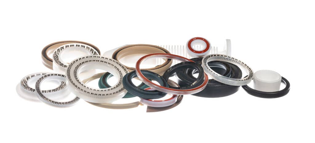
PTFE can reduce friction and retain useful low-temperature properties, but many PTFE pneumatic seals rely on an elastomer energizer. The energizer, mating surface, installation method, and pressure direction remain part of the design. The image above should therefore be read as a seal-construction example, not as proof that any PTFE part fits any cold cylinder.
Use this selection sequence:
- Ask the cylinder manufacturer for the approved low-temperature seal and grease option.
- Confirm that the exact option covers the required pressure, speed, duty, media, and leakage limit.
- Check grease compatibility with seals, guides, coatings, process restrictions, and any downstream exhaust requirement.
- Determine whether the actuator is factory lubricated, non-lube, or intended for continuous airline lubrication.
- Obtain the correct spare seal kit and grease specification for the full model code.
Do not add an airline lubricator merely because the machine is cold. SMC specifically instructs users to operate its -XB7 version without pneumatic-system lubrication. Festo’s CRDSNU catalog says lubricated operation is possible, but once started it must remain lubricated. Those two examples are enough to reject a universal winter lubrication rule.
The broader guide to temperature and cylinder seal selection explains how compound choice changes across both hot and cold service. For a low-temperature cylinder, the manufacturer’s validated seal package should take priority over a generic material table.
Keep Water From Freezing at the Cylinder
Atlas Copco states that refrigerated dryers commonly deliver a 3°C pressure dew point, while desiccant dryers can reach -40°C; it also warns against operating refrigerant dryers in subfreezing ambient conditions (Atlas Copco). A -40°C cylinder cannot compensate for wet compressed air.
Pressure dew point is the temperature at which water vapor begins to condense at the stated compressed-air pressure. Keep it below the coldest temperature reached by the compressed air and internal passages, with an engineering margin that covers dryer variation, measurement uncertainty, demand peaks, and the longest idle period.
Where should the value be checked? Measure at the dryer outlet and at the critical point of use. A remote outdoor branch can receive wetter air than expected because of a failed drain, liquid carryover, an uninsulated low point, a bypass left open, or moisture introduced during maintenance.
The dryer selection belongs to the compressed-air system design, not the cylinder ordering code. The cold-weather pneumatic system guide covers dryers, drains, filters, piping, heat tracing, and winter commissioning in detail. The pressure dew point guide explains how PDP differs from atmospheric dew point.
At the cylinder interface, record:
- required pressure dew point at the stated pressure and sampling location;
- minimum measured media and body temperature;
- filter and dryer pressure drop during maximum demand;
- drain type, freeze protection, and test method;
- allowable particles and oil, not only water content;
- actions taken when dew point or temperature approaches the limit.
ISO 8573-1:2010 treats particles, water, and oil as separate compressed-air purity classes (ISO). A requirement such as “clean, dry air” is therefore incomplete. State the relevant class or numerical limit for each contaminant and identify the measurement point.
How Should Mounting and Accessories Account for Cold?
Festo’s CRDSNU-TT range covers bores from 12 to 100 mm and strokes up to 500 mm, with model-dependent option restrictions (Festo CRDSNU). Across that size range, mounting error and differential contraction can create very different rod, bearing, and seal loads.
Cooling changes dimensions. The amount may be small, but a long frame, rigidly mounted cylinder, guided load, and offset coupler can turn small differential movement into side load. Do not solve this by assigning a universal extra groove depth or clearance. The cylinder manufacturer owns internal tolerances; the machine designer owns the installation geometry.
Check these interfaces:
- Mounting centers: confirm whether the frame and cylinder can contract without pulling the rod off-axis.
- Rod connection: use an approved self-aligning coupler or articulated joint where angular or radial mismatch is credible.
- External guides: let the guide carry side load and keep the cylinder focused on thrust.
- Hard stops: verify that cold contraction does not shift the stop before the cylinder reaches its intended end condition.
- Cushioning: confirm that the cold variant retains the required cushion or external shock absorber arrangement.
- Cable and tube routing: check minimum bend radius and flex rating at the coldest temperature.
- Corrosion protection: account for salt, condensate, washdown, and freeze-thaw exposure separately from temperature.
The most useful tolerance review is a stack-up between the cylinder mounting points, the external guide, and the load connection at both warm and cold limits. It shows whether thermal movement is absorbed by an intended joint or converted into bearing load. The side-loading guide covers the mechanical symptoms in more detail.
Avoid relying on rapid cycling to warm a misaligned or ice-restricted actuator. A cylinder that breaks free unexpectedly can create a motion hazard. Any enclosure heater or heat tracing must also match the electrical area classification, guarding, overtemperature protection, and component manufacturer’s instructions.
How Do You Qualify Cold Start Before Production?
SMC limits the -XB7 version described in its made-to-order specification to a piston speed of 50 to 500 mm/s and tells users to consult SMC for maintenance intervals (SMC -XB7). This demonstrates why a room-temperature catalog cycle cannot qualify cold service.
Cold-soak qualification is a controlled test of the complete assembly after its specified locations have stabilized at the target temperature. Write the plan before the equipment reaches the cold chamber or winter site. Agree the dwell time, load, pressure, cycle profile, instruments, acceptance limits, and recovery procedure.
Establish a warm baseline
Record leakage, breakaway pressure, drive-side and exhaust-side pressure, full-stroke time, end-position signal, cushion behavior, load, and ambient temperature while the machine is healthy. Without this baseline, a cold result is difficult to interpret.
Cold-soak the complete assembly
Soak the cylinder, valve, tubing, fittings, sensors, load, and mounting structure long enough for the specified locations to stabilize. Record actual temperatures. Air temperature outside the chamber does not prove that the grease, end caps, or load structure have reached the target.
Run the first commanded motion safely
Keep personnel outside the hazard zone and follow the machine’s approved startup procedure. Record the first movement after the longest expected idle, not only later cycles after frictional and pneumatic heating have changed the condition.
Compare cold and warm results
Use project-specific limits for:
| Test result | What it can reveal | Acceptance basis |
|---|---|---|
| Breakaway pressure or force | Seal and grease resistance, alignment, load change | Approved design margin and supplier data |
| Port pressure during motion | Valve, tube, regulator, or exhaust restriction | Minimum force and cycle-time requirement |
| External and internal leakage | Seal response, assembly damage, fittings, valve leakage | Project leakage limit and manufacturer specification |
| Stroke time and speed profile | Stiction, restricted flow, cushion setting, load | Machine cycle requirement and rated speed range |
| End-position signal | Sensor, magnet, cable, connector, target position | Safety and control-system acceptance criteria |
| End-of-stroke behavior | Cushion or shock absorber response | Allowable energy, impact, and repeatability |
What if the first cold cycle is slow but the fifth passes? That is still a failed cold-start condition when production or safety requires the first command to work. Keep first-cycle and stabilized-cycle limits separate.
Trend the ratio between cold-start cycle time and the warm baseline under the same load and pressure. The ratio is not a universal acceptance number, but it is a useful site-specific condition indicator. A rising trend can prompt checks of dew point, filters, alignment, leakage, grease condition, or sensor timing before motion is lost.
After testing, inspect the rod, wiper, external ice, fittings, cable jacket, mounts, and load connection. Update maintenance frequency from observed contamination, leakage, cycle-time drift, duty, and failure consequence. Do not copy a generic “three times more often” rule.
What Belongs in a Sub-Zero Cylinder Specification?
ISO 8573-1 separates compressed-air purity requirements into particle, water, and oil classes, while Festo specifies its CRDSNU operating medium as ISO 8573-1:2010 [7:4:4] (ISO; Festo). A usable RFQ must be similarly explicit about both air quality and hardware.
Send suppliers the following data instead of requesting only a “sub-zero cylinder”:
- exact minimum ambient, media, cold-soak, and continuous temperatures;
- maximum temperature and full thermal-cycle profile;
- cylinder type, bore, rod diameter, stroke, action, mounting, and orientation;
- load, external guidance, side-load control, speed, cycles, dwell, and duty;
- supply pressure at the cylinder during motion and allowable exhaust back pressure;
- required seal, grease, wiper, scraper, rod, coating, and corrosion resistance;
- pressure dew point plus particle, water, and oil limits at a named sampling point;
- cushioning, bumper, external shock absorber, or hard-stop requirement;
- magnet, switch, cable, connector, valve, tubing, fitting, and silencer details;
- leakage, breakaway, stroke-time, position, and cold-start acceptance limits;
- applicable safety, food, cleanroom, washdown, hazardous-area, or transport requirements;
- spare seal kit, approved grease, maintenance instructions, and traceable model code.
Ask the supplier to identify every incompatible option and every item whose temperature rating is lower than the cylinder’s. If a requested switch is rated only to -25°C while the cylinder must start at -35°C, the proposal needs a different sensing method or a controlled thermal environment, not a footnote after purchase.
For systems where internal leakage is part of the acceptance test, use a defined pressure, temperature, dwell time, and measurement method. The guide to diagnosing pneumatic cylinder leakage explains why valve state and allowed leakage paths must be separated from the cylinder itself.
Finally, include document revision and retrieval date. Catalog options change. The approved supplier drawing and datasheet should match the exact purchase code released for the machine.
Sub-Zero Pneumatic Cylinder FAQs
SMC’s -XB7 cylinder is rated from -40°C to 70°C, yet its specification excludes auto switches and air cushions and prohibits pneumatic-system lubrication (SMC). These answers focus on why the complete configuration, air quality, and cold-start test matter more than a temperature suffix alone.
Can a standard pneumatic cylinder operate below 0°C?
Possibly, but only inside the exact model’s documented ambient and media ranges and under its no-freezing conditions. “Below zero” is not one duty point. Verify seals, grease, pressure, speed, sensors, tubing, fittings, and compressed-air dryness. If the standard datasheet does not cover the required cold start, select a validated low-temperature variant.
Is FKM always the best seal material for sub-zero cylinders?
No. Parker lists an approximate lower service limit of -26°C for general fluorocarbon and -55°C for low-temperature nitrile, but compound and application details control the result. Dynamic cylinder seals also depend on geometry, grease, pressure, speed, surface finish, media, and leakage limits. Use the cylinder manufacturer’s validated seal package.
Does a -40°C cylinder need a desiccant dryer?
It needs compressed air whose pressure dew point remains below the coldest internal air temperature with an appropriate margin. Atlas Copco places common refrigerated-dryer performance near 3°C and desiccant capability near -40°C. Dryer selection therefore depends on the measured cold point, required PDP, flow, pressure, and site conditions.
Can the standard magnetic sensor stay on a cold-resistant cylinder?
Only if the cylinder option accepts the magnet and the exact sensor, cable, and connector are rated for the minimum temperature. SMC’s -XB7 arrangement can exclude auto switches, while Parker warns that many sensors associated with a -40°C cylinder are rated only to -25°C. Check both ordering codes, not just the cylinder series.
How should a sub-zero pneumatic cylinder be acceptance-tested?
Cold-soak the complete installed assembly to the specified condition, then record the first safe commanded cycle under representative load and pressure. Compare leakage, breakaway, port pressure, stroke time, sensing, and end-of-stroke behavior with defined limits and a warm baseline. Later cycles cannot substitute for a required first-cycle cold start.
Sources and technical references
- SMC: Cold-Resistant Cylinder -XB7 Made-to-Order Specifications
- Festo: CRDSNU Standards-Based Cylinders
- Parker: Pneumatic Actuator Products Catalog
- Parker: P1D Pneumatic Cylinders
- Parker: O-Ring Handbook ORD 5700
- Atlas Copco: Refrigerated and Desiccant Dryer Pressure Dew Points
- ISO 8573-1:2010: Compressed-Air Contaminants and Purity Classes