

Prevent cold-weather pneumatic failures by keeping the compressed air dry enough for the coldest point in the system, confirming the minimum temperature rating of every installed component, and testing the machine at its real winter operating condition. A room-temperature catalog review isn’t enough. The exposed valve manifold, long outdoor drop, and idle machine may be much colder.
The most reliable winter plan starts with measurements. Record pressure dew point at the point of use, minimum pipe and component temperature, dynamic pressure during a cycle, drain operation, and cold-start cycle time. Those readings tell you whether the problem is internal ice, a flow restriction, stiff seals or grease, an electrical component outside its rating, or a mechanical issue that happens to appear in winter.
Key Takeaways
- Refrigerated dryers commonly deliver about 35°F (2°C) pressure dew point; desiccant systems can reach -40°F (-40°C) or lower.
- Select every valve, cylinder, seal, sensor, tube, and lubricant by its exact minimum temperature rating.
- Test drains, dew point, leakage, pressure, and cycle time before the first freeze.
What Actually Fails in a Pneumatic System When It Gets Cold?
The U.S. Department of Energy says refrigerated dryers typically produce a pressure dew point of 35°F (2°C) or higher because their evaporators must remain above 32°F (0°C). If downstream air cools below its pressure dew point, water can condense and freeze inside small passages (DOE, 2003).
Cold-weather faults usually come from one or more of four mechanisms:
- Water condenses and freezes. Ice can restrict a pilot passage, hold a spool, block a drain, or reduce the effective area of tubing and exhaust components.
- Elastomers and grease stiffen. Breakaway friction rises, response slows, and an already marginal actuator may stall or leak.
- Materials and accessories leave their rated range. A cylinder body might tolerate the temperature while its switch, connector, tube, regulator, or seal does not.
- Normal restrictions become more visible. A dirty filter or undersized hose may work in summer but fail when cold seals and lubricant add resistance.
What does this look like on the machine? Common symptoms include a valve that shifts after several attempts, a cylinder that completes its stroke only after warming up, an exhaust silencer coated with ice, intermittent position-sensor signals, and a regulator that recovers slowly after a high-flow event.
Don’t diagnose every winter slowdown as “frozen air.” First separate moisture, temperature, pressure, flow, electrical, and mechanical causes. A spool can stick because of ice, contamination, incompatible grease, or side loading elsewhere in the mechanism. The corrective action is different in each case.
How Do You Establish the System’s Real Minimum Temperature?
SMC lists a made-to-order cold-resistant cylinder option, -XB7, with an ambient temperature range of -40 to 70°C. That model-specific range shows why “pneumatics work below freezing” isn’t a usable specification: standard and cold-resistant versions of similar equipment can have very different limits (SMC, 2026).
Start with the coldest credible operating condition, not the weather station average. Measure or estimate:
- the lowest overnight ambient temperature
- wind-exposed enclosure and pipe temperatures
- compressed-air temperature after expansion or high-flow discharge
- temperature inside unheated cabinets and junction boxes
- warm-up time after a weekend shutdown
- short cold spots near drains, low points, outdoor walls, and metal supports
Place temporary temperature sensors on the components most likely to limit operation: the remote valve manifold, point-of-use filter, cylinder end cap, flexible tube, sensor body, and the lowest exposed pipe section. Record the minimum during normal operation and after the longest expected idle period.
The system minimum is often a location and a moment, not one ambient number. An outdoor line may be coldest before sunrise, while a valve exhaust can cool further during rapid cycling. Treat the lowest measured component temperature and the lowest compressed-air temperature as separate design inputs.
Create a component register with the full model code, minimum ambient temperature, minimum media temperature, seal option, approved lubricant, electrical rating, and evidence source. If any item has no documented rating, it remains an unresolved winter risk.
How Low Should the Pressure Dew Point Be?
Parker places refrigerated drying near 37°F (3°C), while desiccant drying can reach about -40 to -100°F (-40 to -73°C). The target must stay below the coldest temperature encountered after drying, including exposed point-of-use piping (Parker, retrieved 2026).
Pressure dew point is the temperature at which water vapor begins to condense at the stated compressed-air pressure. It is not the same as atmospheric dew point. The pressure dew point guide explains that distinction in detail.
Use this selection sequence:
- Establish the lowest expected compressed-air and internal component temperature.
- Measure pressure dew point at the dryer outlet and at the critical point of use.
- Choose a dryer rating that keeps pressure dew point below the coldest point with a documented engineering margin.
- Include sensor uncertainty, dryer cycling, startup transients, purge performance, seasonal load, and maintenance condition.
- Alarm before the measured pressure dew point reaches the site’s operating limit.
A fixed “20°F below ambient” rule may be a useful company convention, but it is not universal. The margin should reflect the site’s weather data, measurement accuracy, thermal transients, and consequence of failure. A safety-critical outdoor actuator deserves more evidence than an indoor air tool that is occasionally exposed to a cool morning.
Also specify the water class correctly. ISO 8573-1:2010 defines separate compressed-air purity classes for particles, water, and oil. A complete requirement names the applicable water condition or pressure dew point at a stated pressure and sampling location, rather than saying only “ISO-quality air.”
Which Dryer, Filters, and Drains Work in Freezing Conditions?
DOE advises against using refrigerated dryers in subfreezing ambient conditions because condensate can freeze and damage the dryer. Refrigerated units generally suit systems whose downstream air stays above their roughly 35°F (2°C) pressure dew point; colder exposure usually calls for a correctly sized desiccant or membrane solution (DOE, 2003).
Choose the drying method from the required pressure dew point, inlet temperature, flow profile, minimum ambient temperature, allowable pressure drop, energy use, and maintenance capability.
| Drying method | Typical pressure-dew-point capability | Best fit | Cold-weather caution |
|---|---|---|---|
| Refrigerated | About 35 to 40°F (2 to 4°C) | Indoor distribution that remains above freezing | Dryer and downstream piping must stay within the manufacturer’s ambient and media limits |
| Desiccant | Commonly -40°F (-40°C), with lower options available | Outdoor lines, instruments, and freezing exposure | Verify purge loss, regeneration, inlet oil and water control, and dew-point performance |
| Membrane | Application-dependent, with low-dew-point options | Distributed point-of-use drying and limited flows | Performance depends on inlet condition, pressure, flow, and purge settings |
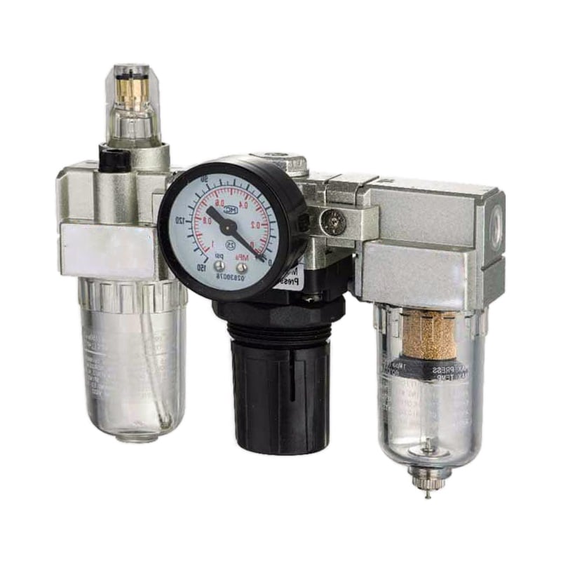
An FRL assembly does not replace a dryer. Its filter can remove liquid water and particles that reach the bowl, but it cannot reduce water vapor to a low pressure dew point. Learn where the distinction matters in the FRL reliability guide.
Drains need equal attention. Install separators and filters where condensate can reach them, follow the required pipe slope and low-point design, and select zero-loss, timed, or float drains from the actual condensate load and freezing exposure. There is no defensible universal “open every 30 seconds” setting.
Can insulation fix a wet-air problem? No. Insulation slows heat transfer but adds no heat. A drain or small-bore line can still freeze after a long shutdown. Use a rated heated enclosure or controlled heat tracing only where the risk assessment, electrical classification, fire protection, and manufacturer instructions allow it.
How Do You Verify Cylinders, Valves, Seals, Tubing, and Sensors?
The Parker O-Ring Handbook lists general nitrile near -30 to 250°F (-34 to 121°C) and low-temperature nitrile near -65 to 225°F (-54 to 107°C). Actual service depends on compound, fluid, pressure, and seal design, so material family alone cannot approve an assembly (Parker, 2021).
Review the complete air path and control chain:
| Component | What to verify | Typical cold-weather failure signal |
|---|---|---|
| Cylinder or actuator | Ambient and media range, seal option, grease, cushioning, switch compatibility | Slow breakaway, incomplete stroke, leakage after idle |
| Directional valve | Pilot pressure, minimum temperature, seal and grease option, exhaust capacity | Delayed shift, intermittent pilot response, frozen exhaust |
| Filter and regulator | Bowl material, drain type, flow curve, temperature range | Cracked bowl, rising differential pressure, slow recovery |
| Tube and hose | Minimum temperature, bend radius, pressure derating, UV and chemical exposure | Cracking, loss of flexibility, fitting pullout |
| Push-in fitting | Tube compatibility and insertion depth at minimum temperature | Intermittent leakage or tube movement |
| Position sensor | Ambient rating, cable flex rating, connector sealing, magnetic compatibility | False or missing end-position signal |
| Silencer | Flow capacity, icing exposure, contamination loading | Slow cylinder or directional speed imbalance |
Don’t substitute a broad material statement for a model check. PTFE, nitrile, polyurethane, fluorocarbon, and silicone each have different friction, elasticity, wear, extrusion, and media-compatibility behavior. Some PTFE seals also rely on an energizer whose low-temperature performance matters.
The same caution applies to metals. “Replace carbon steel with aluminum or stainless steel” isn’t a low-temperature design method. Strength, toughness, corrosion resistance, coating, wall thickness, joining method, and impact-test requirements depend on the exact grade and governing code.
In our experience, accessories are the most frequently missed items in a cold review. The cylinder may have a documented low-temperature option while the standard reed switch, connector, tube, or regulator beside it remains rated for a warmer environment. One out-of-range part can stop the whole machine.
Should You Add or Change Pneumatic Lubrication for Winter?
SMC states that many pneumatic products are lubricated for life at the factory; if external lubrication is supplied, it specifies ISO VG32 Class 1 turbine oil for applicable products and says lubrication must continue once started because the original grease is washed away (SMC, retrieved 2026).
Do not increase lubricator delivery by an arbitrary 20 or 30 percent when the weather turns cold. First determine whether each downstream component is non-lube, pre-lubricated, or designed for airline lubrication. Then use only the oil type, viscosity, feed method, and temperature range approved by the component manufacturer.
For an already lubricated system, check:
- lubricant viscosity at the minimum startup temperature
- pour point and manufacturer-approved operating range
- compatibility with seals, grease, tubing, valves, and process requirements
- lubricator mist performance at actual minimum flow
- whether oil is reaching remote components without excessive delivery near the lubricator
- contamination or product-contact restrictions
ASTM D2270 calculates viscosity index from kinematic viscosities at 40°C and 100°C. It does not establish a universal “VI above 120” requirement for cold-weather pneumatics (ASTM D2270-24, 2024). Pour point also isn’t a complete operating-temperature rating; usable viscosity, pumpability, seal compatibility, and component approval still matter.
If a factory-lubricated actuator becomes slow in winter, don’t install a lubricator as the first response. Confirm pressure dew point, pressure under flow, alignment, load, seal option, grease option, and actual component temperature. Added oil can hide the diagnosis and create a permanent maintenance requirement.
How Should You Protect the Installation and Start It in the Cold?
Parker lists desiccant-dryer pressure dew points of -40°F (-40°C) and below, but dry air does not extend a component’s certified temperature range. Reliable installations combine dry air with rated hardware, controlled drainage, suitable enclosures, and a verified startup procedure (Parker, retrieved 2026).
Use physical protection where it addresses a demonstrated exposure:
- route piping to avoid water traps and unserviceable low points
- keep drains accessible and protect their discharge lines from ice blockage
- shield valve manifolds and sensors from snow, freezing rain, wash water, and wind
- use rated enclosures, heaters, and heat tracing with thermostatic control and alarms
- keep flexible tubing above its minimum bend radius, especially at moving joints
- prevent exhaust moisture from freezing onto walkways, guards, sensors, or adjacent equipment
- place pressure, temperature, and dew-point sensors where technicians can verify the critical condition
Before a cold start, inspect for external ice and damage, confirm dryer and drain status, check dew point and supply pressure, and operate the machine at reduced risk under the approved startup procedure. Watch the first cycles for delayed valves, incomplete strokes, abnormal noise, leakage, and sensor instability.
Why not warm the machine by cycling it rapidly? Because a marginal or ice-restricted actuator can move unpredictably, and repeated stalls may overload the mechanism. Use the machine builder’s safe warm-up method, isolate personnel from motion, and do not bypass guarding or safety circuits.
Track cold-start cycle time as a condition indicator. A gradual increase at the same measured pressure and load can reveal stiffening lubricant, contamination, or a developing restriction before the actuator fails to complete its stroke. Compare it with the warm-state baseline instead of relying on feel.
What Should a Pre-Winter Commissioning and Maintenance Plan Measure?
ISO 8573-1:2010 separates compressed-air purity into particle, water, and oil classes. A winter maintenance plan should therefore record those risks separately rather than treating “air quality” as one pass or fail item. At minimum, trend pressure dew point, drain function, filter differential pressure, leakage, and dynamic machine pressure (ISO, 2010).
Complete a pre-winter baseline while the system is healthy:
- Record minimum temperature at each exposed critical point.
- Verify dryer capacity and pressure dew point at the dryer outlet and remote point of use.
- Test every automatic drain and inspect low points for trapped water.
- Record pressure before and after filters, regulators, valves, and long branches during the highest-flow event.
- Measure cold and warm cycle time, breakaway behavior, and end-position repeatability.
- Perform an isolation or pressure-decay leak test under comparable temperature conditions.
- Test enclosure heaters, thermostats, alarms, sensors, and backup power where applicable.
- Confirm spare seals, drain kits, filters, valves, and sensors match the approved low-temperature models.
Set maintenance frequency from evidence. A remote outdoor drain with high condensate load may need more attention than an indoor desiccant-dried instrument branch. Use manufacturer intervals as the floor, then shorten them only when trend data, environment, duty, or failure consequence justifies it.
Define action limits before winter. Examples include maximum acceptable pressure dew point, filter differential pressure, cold-start cycle time, leakage rate, minimum dynamic pressure, heater alarm temperature, and drain-test failure. Site engineering must set the values from product data and process risk, not copy generic percentages from a blog.
How Do You Troubleshoot a Cold-Weather Pneumatic Fault?
DOE recommends keeping total compressed-air distribution pressure drop well below 10 percent of compressor discharge pressure. That benchmark matters in winter because ice, contaminated filters, stiff components, and undersized tubing can add local restriction. Measure pressure while the fault occurs rather than raising the compressor setpoint to mask it (DOE, 2003).
| Symptom | First measurements | Likely directions | Corrective action |
|---|---|---|---|
| Valve will not shift after a cold idle | Valve temperature, pilot pressure, dew point, coil voltage | Ice, low pilot pressure, out-of-range seal or grease, electrical issue | Dry and safely warm as approved; correct air quality, pressure, or component selection |
| Cylinder is slow only when cold | Dynamic pressure, stroke time, load, alignment, exhaust pressure | Stiff seals or grease, restriction, frozen silencer, mechanical drag | Isolate the restriction; verify cold-rated actuator and accessories |
| Regulator pressure falls during motion | Upstream and downstream dynamic pressure, filter differential | Filter ice or loading, regulator undersizing, branch restriction | Service the air path and compare required flow with published curves |
| Leak increases as temperature falls | Leak location, component temperature, tube insertion, seal condition | Seal contraction, cracked tube, loose fitting, damaged component | Replace with compatible rated parts; don’t compensate by raising pressure |
| Position feedback becomes intermittent | Sensor temperature, supply voltage, cable and connector condition | Sensor outside rating, cable damage, moisture ingress, target shift | Correct the electrical or mounting fault with a rated sensor assembly |
| Drain stops discharging | Bowl level, drain temperature, discharge-line condition | Frozen mechanism or outlet, contamination, no differential pressure | Isolate safely, thaw by approved method, repair drainage and freeze protection |
If pressure is normal at rest but falls during movement, follow the dynamic pressure-drop troubleshooting process. If dew point rises at the remote machine while the dryer outlet remains acceptable, inspect downstream ingress, dead legs, saturated piping, and the sampling method.
Never apply an open flame to a frozen valve, pipe, drain, or receiver. Isolate energy, release trapped pressure through the approved method, control unexpected motion, and follow the equipment and site lockout procedure before inspection or thawing.
What Information Should You Send for a Cold-Weather Retrofit or RFQ?
Parker’s nitrile examples differ by nearly 20°C, while SMC’s -XB7 cold-resistant cylinder reaches -40°C. Those figures aren’t interchangeable approvals. An RFQ must identify the operating conditions and complete model configuration (Parker, 2021; SMC, 2026).
Send the supplier:
- minimum, normal, and maximum ambient temperature
- minimum compressed-air and component surface temperature
- pressure dew point requirement, operating pressure, and measurement location
- minimum dynamic pressure and peak flow during the machine cycle
- actuator bore, stroke, load, speed, orientation, cushioning, and duty profile
- full model codes for valves, regulators, filters, drains, sensors, tubing, and fittings
- current seal, grease, and lubrication arrangement
- outdoor exposure, wind, precipitation, washdown, salt, dust, UV, and hazardous-area conditions
- enclosure, heater, trace-heating, alarm, and electrical requirements
- observed symptoms, temperature when they occur, and trend data
- applicable machine-safety, compressed-air-quality, electrical, and local code requirements
For an existing machine, include nameplate and installation photos, a marked pneumatic diagram, dryer data, pressure and temperature logs, and the timing of the fault within the production cycle. This lets the supplier review the operating point rather than recommending a generic “winter package.”
The high-temperature cylinder guide covers the opposite thermal extreme, but the selection principle is the same: the weakest rated seal, grease, switch, tube, or accessory can determine the assembly limit.
David Li’s compressed-air system role is listed on About Us. For a model-level cold-weather review or retrofit RFQ, send the operating data through the contact page.
FAQs About Cold-Weather Pneumatic Systems
Refrigerated drying provides 35 to 40°F (2 to 4°C) pressure dew point; desiccant systems reach -40°F (-40°C). No single failure temperature applies because moisture, ratings, pressure, and duty differ (DOE, 2003; Parker, retrieved 2026).
At what temperature do pneumatic systems start having problems?
There is no universal threshold. Water may condense when compressed air cools below its pressure dew point, while seals, grease, sensors, tubing, and valves have separate model-specific minimum temperatures. A system can fail above 32°F if its air is wet, or operate below 0°F when it is correctly dried and rated.
Is a refrigerated dryer enough for outdoor winter pneumatics?
Usually not when the downstream air or dryer ambient can fall below freezing. Refrigerated dryers commonly provide pressure dew points near 35 to 40°F, and DOE advises against subfreezing ambient operation. Use the measured minimum temperature and required dew point to evaluate a desiccant, membrane, heated enclosure, or combined solution.
Can I retrofit an existing pneumatic machine for cold weather?
Often, but the retrofit may involve more than a heater. Measure point-of-use pressure dew point and dynamic pressure, then verify cylinders, valves, seals, sensors, tubing, drains, grease, and enclosures by model. Replace only the limiting parts and revalidate machine safety, cycle time, leakage, and air quality at minimum temperature.
Should I use synthetic oil in a cold pneumatic system?
Not by default. Use only the lubricant type, viscosity, and temperature range approved for every downstream component and the process. Many pneumatic products are factory-lubricated and need no airline oil. If external lubrication is started, some manufacturers require it to continue, so changing oil policy needs a documented compatibility review.
How often should a pneumatic system be inspected during winter?
Use risk and condition data, not a generic 50 or 100 percent increase. Establish pre-winter baselines for pressure dew point, drain function, differential pressure, leakage, cold-start cycle time, heaters, and alarms. Inspect at the manufacturer interval or more often when trends, exposure, duty, or failure consequence justify it.
What is the first test when a pneumatic machine slows down in the cold?
Measure pressure at the actuator or valve inlet while the slow motion occurs, then compare component temperature and pressure dew point with the approved limits. This separates a supply restriction from ice, stiff seals, exhaust blockage, or mechanical drag. A static compressor-room gauge cannot capture a short point-of-use pressure sag.
Sources
- U.S. Department of Energy: Improving Compressed Air System Performance, dryer selection, condensation, freezing exposure, and distribution pressure drop. Retrieved 2026-07-17.
- Parker: Drying Compressed Air Guide, refrigerated, desiccant, and membrane drying capabilities. Retrieved 2026-07-17.
- ISO 8573-1:2010, compressed-air purity classes for particles, water, and oil. Retrieved 2026-07-17.
- Parker O-Ring Handbook, ORD 5700, elastomer temperature guidance and application limits. Retrieved 2026-07-17.
- SMC Environment-Resistant Cylinders, model-specific cold-resistant cylinder range. Retrieved 2026-07-17.
- SMC Lubrication Guidelines, factory lubrication, ISO VG32 guidance, and continuous lubrication warning. Retrieved 2026-07-17.
- ASTM D2270-24, viscosity-index calculation method and scope. Retrieved 2026-07-17.