

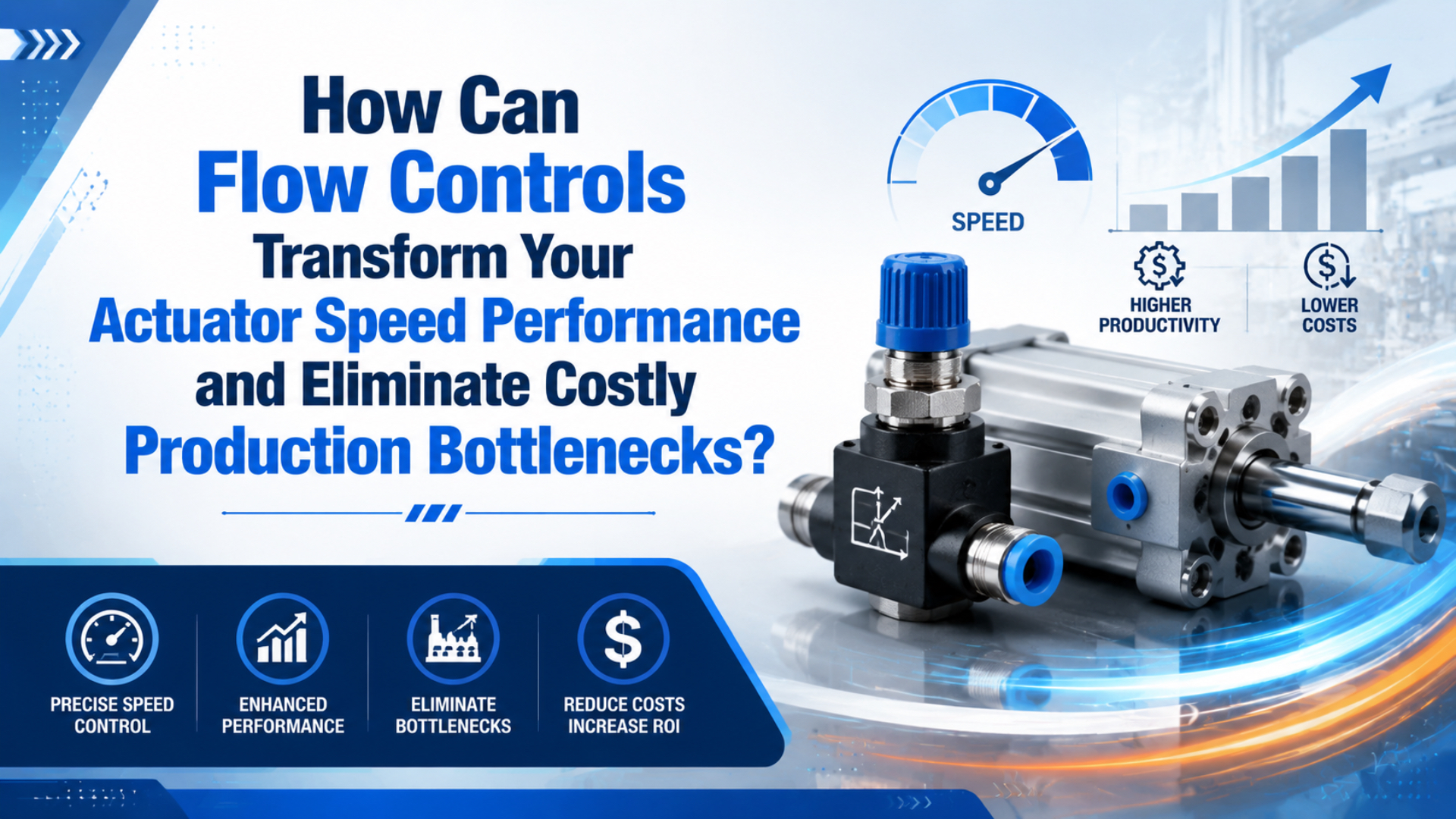
Actuator speed performance is the measured ability of a pneumatic actuator to complete each loaded stroke inside its time window without unstable motion or damaging impact. Flow controls improve it by setting how quickly each cylinder chamber fills or exhausts. Used as a cure for an undersized valve or collapsing supply, they only hide the real restriction.
The fastest route to a stable setting is measurement, not trial and error. Record loaded stroke time, pressure at the actuator while it moves, valve orientation, tube size, exhaust condition, and cushion behavior. Then calculate the required flow and adjust one direction at a time.
Key Takeaways
- SMC relates cylinder speed to flow with
s = 28.8q/Awhen inlet pressure is held constant.- Calculate extension and retraction demand separately; never divide a per-minute flow by 60 again.
- Prove the result with dynamic pressure and repeated loaded cycles, not the regulator’s static gauge.
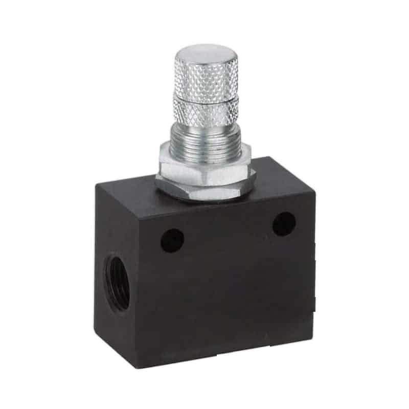
For valve families and functions, use the broader guide to pneumatic flow control valve types. This article stays on commissioning and troubleshooting an actuator that is missing its speed target.
How Does Flow Control Change Actuator Speed Performance?
Airflow sets cylinder speed when pressure and load are stable. SMC expresses the relationship as s = 28.8q/A, where s is inches per second, q is SCFM, and A is piston area in square inches (SMC, accessed 2026). More usable flow raises speed; more piston area lowers it.
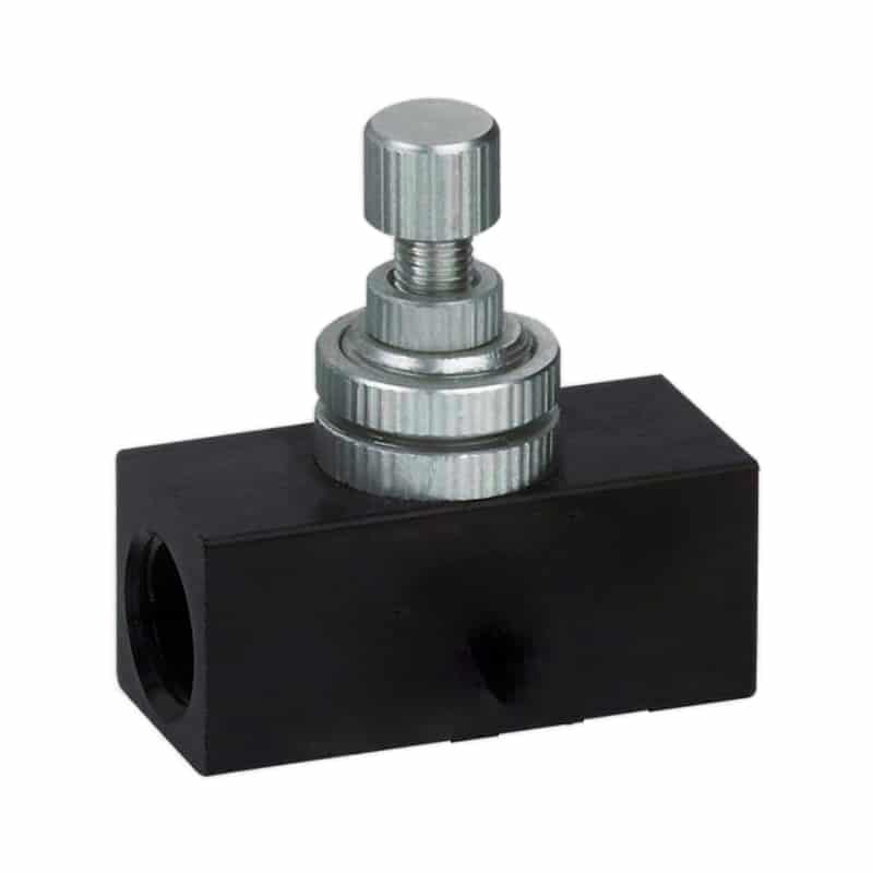
A manual flow control normally combines an adjustable needle with a check-valve bypass. In one direction, air passes through the check with little restriction. In the other, it passes through the needle. Two controls at a double-acting cylinder’s ports let you tune extension and retraction separately.
Meter-out flow control is an arrangement that allows supply air into the active chamber while restricting exhaust from the opposite chamber. It is the usual starting arrangement because the exhaust restriction creates stabilizing back pressure. SMC identifies exhaust-side control as common industry practice. Parker likewise specifies models whose free-flow direction is into the cylinder and metered direction is out of it (Parker Hannifin, accessed 2026).
Meter-out is not a universal answer. A predictable horizontal resistive load may work with meter-in, while a load that assists motion usually needs exhaust-side restraint. The full decision boundary belongs in the dedicated meter-in vs meter-out guide.
What if the needle is fully open and the cylinder is still slow? The bottleneck is probably elsewhere: directional-valve capacity, tubing ID, a restrictive fitting, a contaminated muffler, low dynamic pressure, guide friction, or insufficient force margin. A speed controller can reduce available flow. It cannot create flow the circuit never delivers.
What Should You Measure Before Turning the Needle?
Measure pressure during motion, not only at rest. CAGI says a well-designed compressed-air system should exhibit no more than 10% pressure drop from compressor discharge to the point of use (CAGI, accessed 2026). A local branch, valve, tube, or muffler can still produce a short pressure collapse during the stroke.
Dynamic pressure is the pressure measured close to the actuator while air is flowing and the piston is moving. It is more useful than a static regulator reading when the question is whether the valve and local air path can support the commanded stroke.
Capture a baseline with the real payload and normal upstream demand. Record at least these values:
| Measurement | Where or how to measure | What it tells you |
|---|---|---|
| Extend and retract time | Command edge to end sensor | Which direction misses the target |
| Static supply pressure | Near the actuator before motion | Available starting condition |
| Dynamic port pressure | Tee near the active cylinder port | Whether supply collapses during motion |
| Exhaust back pressure | Opposite cylinder port, if practical | Whether restriction is excessive |
| Tube OD, ID, and length | Valve to cylinder on both sides | Whether the local air path is undersized |
| Needle position | Count turns from a repeatable reference | Allows settings to be restored |
| Load and mounting direction | Actual production condition | Identifies overrun and force changes |
| End impact and cushion setting | Observe the last part of travel | Separates speed from stopping energy |
In our experience, the most reliable application review separates a speed complaint into three time blocks: valve response, pressure build or exhaust delay, and physical travel. If the command changes promptly but port pressure builds slowly, changing the cylinder rarely helps. If pressure is present and the carriage hesitates, friction, alignment, load, or force margin moves higher on the list.
Also check the arrow or circuit symbol on each flow control. Identical-looking parts can be meter-in, meter-out, or bidirectional. Reversing a one-way control can turn a stable exhaust restriction into an unstable inlet restriction without changing the needle position.
How Much Flow Does the Actuator Actually Need?
A 63 mm bore cylinder with a 500 mm stroke has about 1.56 L of cap-end swept volume. At 6 bar gauge, that chamber represents roughly 10.9 standard liters per extension when referenced to 1 bar absolute. A 1-second extension therefore needs about 655 L/min of ideal free-air flow before dead volume, leakage, and margin are considered.
Start with chamber geometry:
Cap-end area = pi x bore^2 / 4
Rod-end area = pi x (bore^2 - rod^2) / 4
Chamber volume = effective area x stroke
Convert working-volume demand to free-air demand with absolute pressure:
Free-air volume = chamber volume x working absolute pressure / reference absolute pressure
Then use the target time:
Required free-air flow (L/min) = free-air volume (L) x 60 / stroke time (s)
For example, consider a 63 mm bore, 20 mm rod, 500 mm stroke cylinder at 6 bar gauge, assuming 1 bar absolute reference:
| Direction | Swept volume | Free air per stroke | Target time | Ideal required flow |
|---|---|---|---|---|
| Extension | 1.559 L | 10.91 L | 1.0 s | 655 L/min |
| Retraction | 1.402 L | 9.81 L | 0.8 s | 736 L/min |
These are pre-selection values, not guaranteed machine results. The valve maker’s rating method, inlet pressure, outlet pressure, temperature, tube losses, and exhaust restriction still matter. ISO 6358-1 defines steady-state test methods for pneumatic component flow characteristics, which is why catalog flow data should be compared under stated pressure conditions.
Do not select a control from thread size alone, and do not apply a universal 150% or 200% multiplier. Calculate the target, review the manufacturer’s flow curve or ISO 6358 data, account for the complete path, and leave an adjustment range appropriate to the machine. The flow control valve sizing guide covers Cv and catalog comparison in more detail.
We found a useful diagnostic rule when pairing the calculation with a pressure trace. If opening the flow control shortens the stroke while dynamic pressure stays stable, the local restriction was controlling speed. If the needle is open, stroke time remains long, and pressure falls during motion, the bottleneck has moved upstream. That distinction prevents repeated valve adjustments from masking supply starvation.
How Should You Commission a Manual Flow Control?
Catalog capacity can vary sharply even within one product family. Parker’s 3251 meter-out series lists adjusted Cv values from 0.26 for a 1/8-inch model to 1.64 for a 1/2-inch model (Parker Hannifin, accessed 2026). A familiar port style therefore doesn’t prove that a valve can meet the target stroke time.
Before commissioning, isolate energy according to the machine’s safety procedure, support suspended loads, and keep personnel outside the actuator’s travel and pinch zones. Flow controls regulate motion; they are not isolation devices, load-holding devices, or safety-rated stops.
Use this sequence after the machine is safe and ready for controlled testing:
- Confirm the part number, flow direction, pressure rating, tube size, and cylinder port connection.
- Back the cushion adjustment away from an extreme setting so it doesn’t dominate the entire stroke. Keep enough cushioning to prevent a hard stop.
- Set both one-way controls to a conservative low-speed starting point. Follow the valve manufacturer’s direction; don’t force a needle against its seat.
- Restore pressure gradually and jog the actuator without production load if the risk assessment permits.
- Tune the direction with the higher hazard or load-assisted motion first, normally using meter-out.
- Open the controlling needle in small increments until the loaded stroke reaches its target without bounce or end impact.
- Tune the opposite direction independently.
- Recheck dynamic pressure, sensor arrival, and force margin at the lowest expected supply condition.
- Apply the real payload and run consecutive cycles.
- Lock the adjuster and record turns, pressure, load, stroke times, valve part number, and test date.
Don’t use “50% open” as a universal starting specification. Needle geometry and useful adjustment range differ by valve. Counting turns from a documented reference is more repeatable, but even turn count doesn’t replace a measured stroke time.
For example, a long tube between the control and cylinder adds compressible volume and delay. Port-mounted controls usually respond more predictably, but service access, vibration, environment, and fitting loads still have to be checked. If the machine needs recipe-based speed changes rather than one fixed setting, stop stretching a manual needle valve beyond its job and review proportional valves for precision motion control.
Symptom-Based Troubleshooting
The first stroke after repressurization needs separate attention. Parker’s P33 soft-start documentation describes opening fully when downstream pressure reaches approximately 50% of inlet pressure and warns that meter-out controls may not regulate the first actuation properly while a depressurized system is refilling (Parker Hannifin, accessed 2026).
Use the motion symptom to select the next measurement:
| Symptom | Likely causes | First test | Corrective direction |
|---|---|---|---|
| Fast, hard end impact | Needle too open, cushion ineffective, low moving-load restraint | Compare mid-stroke speed with final 20% of travel | Reduce speed, then tune or verify cushioning |
| Slow in both directions | Low dynamic pressure, small directional valve, small tube, blocked muffler | Measure port pressure during both strokes | Remove the dominant upstream or exhaust restriction |
| Smooth extension, violent return | Opposite control reversed or open, load assists return | Verify symbol and exhaust path for return | Correct orientation and tune return independently |
| Starts slowly, then jumps | Stiction, guide misalignment, meter-in on an overrun load | Compare breakaway pressure and carriage alignment | Correct mechanics; test meter-out if load assists motion |
| Speed changes when other stations run | Shared supply pressure drop or limited local storage | Trend point-of-use pressure with stations synchronized | Improve branch capacity, sequencing, or local air supply |
| Gets slower over time | Contamination, damaged tube, clogged silencer, seal or guide wear | Inspect differential pressure and mechanical drag | Service the identified restriction or wear source |
| First cycle slams after startup | Downstream volume not pressurized, meter-out not yet effective | Compare first and later cycles | Use a suitable soft-start and safe startup sequence |
| Needle adjustment has little effect | Control is reversed, bypassing, oversized, or not the bottleneck | Move through a controlled adjustment range while timing | Confirm direction, valve range, and upstream capacity |
Static pressure can look healthy while the moving actuator starves. If the broader cylinder fault is still unclear after these tests, use the pneumatic cylinder troubleshooting guide to separate leakage, alignment, seal, load, and valve problems.
Avoid raising supply pressure as the first response. More pressure may recover force, but it can also increase end impact and air consumption while leaving the restrictive path unchanged. Measure first. Change one variable at a time.
How Do Cushioning and Exhaust Restrictions Interact?
Doubling impact speed increases kinetic energy by a factor of four because E = 1/2 mv^2. Festo explains that pneumatic end cushioning must account for moving mass, speed, desired deceleration, working pressure, and cylinder resistance (Festo, accessed 2026). Speed control and cushioning therefore solve connected but different parts of the motion.
The flow control sets the approach speed across most of the stroke. Cushioning manages the final portion by trapping and metering air near the end position. Closing the cushion too far can make the last part of the stroke crawl or prevent the end sensor from switching. Opening it too far can produce bounce, noise, or hard impact.
Tune them in this order:
- Set a safe mid-stroke speed with the external flow control.
- Adjust cushioning so deceleration begins near the end without a long stall.
- Recheck total stroke time and end-sensor repeatability.
- Repeat at minimum and maximum production load.
Exhaust silencers are part of this loop. A clogged or undersized muffler adds back pressure after the directional valve. It may slow both directions, change meter-out authority, and reduce net cylinder force. Removing a silencer for diagnosis can create unsafe noise and contamination exposure, so replace it with a correctly rated component rather than operating the machine without exhaust protection.
For very fast exhaust requirements, a quick-exhaust valve can shorten the exhaust path, but it also changes noise, cushioning, and speed-control behavior. Treat it as a circuit redesign, not a shortcut around measurement.
Verify That the Production Bottleneck Is Gone
Verification needs both pressure and time. SMC’s speed relation assumes inlet pressure is held constant, while CAGI’s system guidance uses a 10% maximum pressure-drop target from the compressor to the point of use (SMC, accessed 2026; CAGI, accessed 2026). A faster average means little if pressure or cycle time is unstable.
Use a short acceptance record rather than a single stopwatch result. Twenty consecutive loaded cycles is a practical commissioning sample, not a universal standard. Record the minimum, maximum, average, and any missed end-sensor transitions for extension and retraction.
| Acceptance check | Pass condition to define for the machine |
|---|---|
| Loaded stroke time | Every cycle remains inside the process window |
| Dynamic pressure | No unexplained collapse at the active cylinder port |
| End impact | No bounce, hard stop, or cushion stall |
| Sensor sequence | End signal arrives before the controller timeout on every test cycle |
| Force margin | Cylinder completes the stroke at lowest expected supply and highest load |
| Restart behavior | First cycle after safe repressurization remains controlled |
| Setting retention | Locknut or protected adjuster holds the documented position |
| Interaction with other stations | Simultaneous demand does not push the stroke outside its limit |
The best bottleneck test compares the actuator’s time contribution with the machine’s critical path. NIST describes Overall Equipment Effectiveness as a manufacturing metric built from availability, performance, and quality, so an actuator change should be judged by its effect on the production system rather than speed alone (NIST, 2019). Saving 100 ms on a cylinder that finishes before another station doesn’t increase throughput. Saving 50 ms on the operation that gates every cycle can. Confirm the control sequence before chasing the fastest possible motion.
Document the accepted setting as a controlled machine parameter. Review it after changes to load, tubing, valve model, silencer, regulator, cylinder, guide, or software timing. A fixed quarterly adjustment can create drift where none existed; condition-based verification after relevant changes is more defensible.
FAQs About Flow Controls and Actuator Speed
Flow remains the central variable, but SMC notes that port and tubing size also affect actuator speed in addition to the s = 28.8q/A relationship (SMC, accessed 2026). These answers keep speed adjustment separate from valve sizing, pressure loss, cushioning, and safety.
Should pneumatic cylinder speed be controlled with meter-in or meter-out?
Start with meter-out for most double-acting cylinders, especially vertical, variable-load, or overrun-prone motion. It restricts exhaust and creates stabilizing back pressure. Meter-in can suit predictable horizontal resistive loads. Confirm the valve’s check direction, test with the real load, and verify that exhaust back pressure doesn’t remove needed force margin.
Why does a cylinder remain slow when the flow control is fully open?
The flow control may not be the limiting component. Measure pressure near the cylinder during motion, then inspect directional-valve capacity, tube ID and length, fittings, quick couplers, FRL elements, exhaust mufflers, guide friction, and load. If dynamic pressure falls while the needle is open, correct the upstream restriction before changing the cylinder.
Can one flow control set both extension and retraction speed?
A bidirectional needle can restrict both directions, but it doesn’t provide independent settings. Double-acting cylinders also have different cap-end and rod-end effective areas, so equal flow doesn’t necessarily produce equal speed. Two one-way controls at the cylinder ports normally give better control over extension and retraction as separate machine motions.
Does a flow control reduce cylinder force?
It can. A meter-out restriction raises exhaust-side back pressure, which subtracts from the pressure differential producing net force. A meter-in restriction can slow pressure build on the active side. If the cylinder stalls after tuning, measure both port pressures during motion and review load, bore, friction, valve capacity, and tube losses.
How often should flow-control settings be checked?
Check them after changes that can alter flow or mechanics: valve or tube replacement, load changes, silencer service, regulator changes, cylinder work, guide alignment, or control-sequence updates. Also investigate a measured trend in stroke time. Don’t turn a stable locked adjustment on a fixed calendar merely to satisfy a maintenance habit.
Can a manual flow control produce programmable speed profiles?
No. A manual needle provides a fixed restriction. It cannot command different speeds by recipe or close a feedback loop around carriage motion. When the process needs remote setpoints, multi-stage profiles, or load compensation based on measured motion, review a proportional or servo-pneumatic architecture rather than repeatedly resetting a manual valve.
Sources
- SMC: Control Air Flow of Cylinders, speed relation
s = 28.8q/A, constant-inlet-pressure condition, exhaust-side control, and tube or port effects. Accessed 2026-07-17. - Parker Hannifin: Flow Controls & Accessories, flow direction, port mounting, adjusted Cv values, pressure ratings, and product flow data. Accessed 2026-07-17.
- Parker Hannifin: P33 Modular Exhaust Valve Instructions, soft-start behavior and first-actuation warning for depressurized meter-out circuits. Accessed 2026-07-17.
- CAGI: Pressure Drop FAQs, 10% point-of-use pressure-drop guidance and distribution-system restrictions. Accessed 2026-07-17.
- ISO 6358-1:2013, steady-state flow-rate characteristic testing for pneumatic components using compressible fluids. Accessed 2026-07-17.
- Festo: Cylinder Cushioning, the Three Most Common Methods, cushioning variables and adjustment principles. Accessed 2026-07-17.
- NIST: Manufacturing Science and Engineering Conference Proceedings, Overall Equipment Effectiveness as an availability, performance, and quality metric. Accessed 2026-07-17.