

High-force pneumatic actuators for pressing and clamping can shorten a machine cycle when the job needs fast, repeatable end-to-end motion and the required force still fits practical air pressure, bore, and machine-space limits. The transformation comes from choosing the right force architecture, not from feeding ordinary cylinders with unapproved pressure.
Start at the workpiece. Define the pressing load or the disturbance the clamp must resist, then follow that force through the tooling, linkage, actuator, frame, valve, and air supply. If any part of that chain is guessed, a large catalog force can still produce an unreliable fixture.
Key Takeaways
- A 125 mm Parker P1D cylinder produces 7,363 N theoretical extension force at 6 bar.
- Festo’s ADNH uses two to four pistons to multiply advance force without raising supply pressure.
- Clamp force depends on arm geometry, contact, pressure at the actuator, and frame stiffness.
- Guarding and safe isolation remain separate design tasks.
What Counts as a High-Force Pneumatic Actuator?
A high-force pneumatic actuator increases usable thrust through piston area, multiple pistons, or mechanical advantage. Festo’s 2025 range overview describes two-, three-, and four-cylinder arrangements that approximately double, triple, or quadruple advance force compared with one cylinder of the same diameter (Festo tandem/high-force cylinders, 2025).
A high-force pneumatic actuator is a cylinder or cylinder-mechanism assembly selected to deliver a defined workpiece force that an ordinary single-piston layout can’t provide within the allowed pressure and space. That definition is more useful than a fixed threshold. A 4,000 N clamp may be substantial for a small fixture but modest for a press fit.
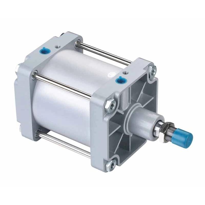
A large-bore ISO 15552 standard cylinder is the simplest architecture. It converts pressure directly into rod thrust. A tandem cylinder stacks working pistons along one rod, while a power clamp adds a toggle or linkage that changes cylinder motion into higher workpiece force near the closed position.
These mechanisms aren’t interchangeable. A large-bore cylinder usually provides force through its stroke. A toggle clamp may deliver its highest mechanical advantage only near full closure. A tandem unit can multiply extension force but still have a different retraction limit. What matters to your fixture: full-stroke force, closing force, final clamp force, or stored holding force?
The phrase “high force” should therefore describe the complete load path. The same actuator can be adequate at the rod and inadequate at the workpiece if a long clamp arm flexes, a pivot binds, or the frame opens under reaction load. Catalog thrust is one input. It isn’t the acceptance test.
How Much Pressing or Clamping Force Does the Process Need?
Required force must be defined at the tool or workpiece before cylinder sizing begins. SMC rates one 63 mm CKZ3N power clamp at 4,000 N only with a 100 mm arm and 0.5 MPa supply, showing why bore and pressure alone can’t define clamping force (SMC CKZ3N catalog, 2024).
For a press, begin with the verified process force: insertion force, forming force, staking force, spring compression, or test load. Include the direction of force, the distance over which it acts, alignment tolerance, and whether the load rises sharply near the end of stroke. A peak-only number can hide a difficult force-distance curve.
For a friction clamp, the workpiece must stay still while cutting, welding distortion, inertia, gravity, or another disturbance acts on it. A first model can be written as:
Required normal clamp force >= disturbing force / usable friction coefficientThat equation is only a starting point. Use the number of effective contacts, their directions, surface condition, lubrication, vibration, and the consequences of slip. Don’t copy a generic friction coefficient or safety factor into a release drawing without testing the real interface.
For a toggle or swing clamp, use the manufacturer’s clamp-force curve for the selected arm length, pressure, and closing angle. SMC’s 4,000 N example is tied to those three conditions. Extending the arm changes the moment balance, so a longer arm doesn’t preserve the same force at the pad.
| Application | Force to define first | Boundary condition that changes the answer |
|---|---|---|
| Press fit | Peak force over insertion distance | Part tolerance, alignment, lubrication, and stop position |
| Machining clamp | Normal force needed to resist tool load | Contact friction, clamp direction, vibration, and part distortion |
| Welding fixture | Force needed to locate and restrain the assembly | Thermal distortion, spatter protection, arm stiffness, and access |
| Bearing insertion | Measured insertion-force profile | Interference, lead-in geometry, speed, and acceptance window |
How much margin is enough? Parker’s P1D catalog advises selecting theoretical cylinder force 50% to 100% above the required force, but that catalog guidance doesn’t replace an application risk review (Parker P1D Series catalog, 2014). Vertical loads, personnel exposure, variable friction, and hard tooling can require different controls rather than simply a larger cylinder.
How Do Pressure and Bore Become Available Actuator Force?
Theoretical cylinder force follows pressure times effective area. Parker lists 7,363 N extension force for a 125 mm P1D at 6 bar, but it also recommends substantial force margin because friction and operating conditions reduce usable output (Parker P1D Series catalog, 2014).
For extension on a conventional double-acting cylinder:
Piston area = pi x bore^2 / 4
Theoretical extension force = pressure x piston area
For retraction, subtract rod area from piston area. Then subtract opposing chamber pressure, seal friction, spring force, and any mechanical losses. This is why a pressure-area formula is necessary but not sufficient.
| P1D bore | Theoretical extension force at 6 bar | What still needs checking |
|---|---|---|
| 32 mm | 483 N | Load direction and breakaway friction |
| 40 mm | 754 N | Rod-side force if pulling |
| 50 mm | 1,178 N | Port pressure during motion |
| 63 mm | 1,870 N | Mount and guide reaction |
| 80 mm | 3,016 N | Valve and tube flow |
| 100 mm | 4,712 N | Frame deflection and cushioning |
| 125 mm | 7,363 N | Air demand and available installation space |
These are catalog theoretical values, not guaranteed fixture force. Measure dynamic pressure at the active cylinder port while the machine runs. A regulator reading taken at idle can look healthy even when a valve, fitting, tube, silencer, or shared header limits flow during the press stroke.
If required load is already known, use the Cylinder Bore Size Calculator as a secondary check. Round up to a real catalog bore, then repeat the review with the selected cylinder’s pressure rating, mounting, rod size, speed range, and cushioning data.
The best pressure value for sizing isn’t the compressor setpoint or even the regulator setting. It’s the lowest repeatable active-chamber pressure during the force-producing part of the stroke. That single distinction separates a static spreadsheet from a machine that holds force during peak air demand.
Which High-Force Architecture Fits the Station?
Architecture changes the force profile as much as bore does. At 6 bar, Festo lists 18,281 N advance force for a four-piston, 100 mm ADNH, while retraction is 4,417 N because only one cylinder contributes on return (Festo ADNH technical data, 2010).
That example captures the main tandem tradeoff: more forward force without higher supply pressure, but added length, air volume, and asymmetric return performance. If your process needs equal push and pull force, the arrangement must be checked in both directions.
| Architecture | Best fit | Main limitation to verify |
|---|---|---|
| Large-bore cylinder | Direct push or clamp with enough radial space | Air demand, rod guidance, frame reaction, and rated pressure |
| Tandem cylinder | Higher advance force where diameter is constrained | Package length, volume, return force, and external stop requirements |
| Toggle clamp | High fixture force near the closed position | Arm length, closing angle, lock state, pad position, and tolerance |
| Booster or air-over-oil unit | Short force event with a validated high-pressure circuit | Downstream ratings, relief, isolation, heat, and cycle rate |
| Hydraulic or electric axis | High force density, stiffness, controlled force, or programmable motion | Power unit or drive cost, maintenance, guarding, sensing, and ownership |
A booster isn’t permission to exceed a cylinder rating. Parker rates the referenced P1D series to a maximum of 10 bar. If a process needs higher pressure, the actuator, valve, tubing, fittings, gauges, seals, relief devices, and isolation method must all be designed for that pressure.
Could a toggle mechanism solve the same problem with less air? Often it can near the closed position, but only if the workpiece tolerance still lets the linkage enter its intended force range. A worn pivot or unexpected part thickness can shift the geometry and change pad force.
For a broader system boundary, compare this decision with hydraulic versus pneumatic power. Keep the present decision tied to one station, one force profile, and one safe failure state.
Can Pneumatics Replace Hydraulics in Every High-Force Job?
No. Bimba’s design guide says most pneumatic systems operate near 100 psi, while some hydraulic systems work at 3,000 to 5,000 psi, so hydraulics usually wins when force density and stiffness dominate (Bimba Pneumatic Actuators Design Guide, 2019).
Pneumatics is attractive when the station needs fast end-to-end motion, the plant already has suitable air, the environment favors clean hardware, and the required force fits an acceptable bore or tandem package. OSHA also notes that pneumatic presses offer speed and cleanliness but cannot supply the extreme pressures available from hydraulic presses (OSHA Pneumatic Presses, 2026).
Hydraulics is usually the stronger candidate when a compact envelope must produce very high force, the process needs high stiffness, or the ram must hold and control heavy loads through a force-distance profile. Electric pressing can be preferable when programmable position, speed, and force data are central to quality control.
Don’t compare actuator purchase prices in isolation. A pneumatic station depends on compressor capacity, air treatment, storage, distribution, valves, exhaust treatment, and energy. A hydraulic station carries a power unit, fluid management, filtration, cooling, and leak controls. The useful comparison freezes the same load, stroke, cycle rate, quality requirement, safety state, and ownership boundary.
What if the plant already owns compressed air? That lowers the project boundary, but it doesn’t make the air free or guarantee enough peak flow. Review the full duty with the working-pressure guide before promising a hydraulic replacement.
What Must Be Verified Before Production Release?
Pressure at the point of use should stay within the machine’s validated range throughout the force stroke. CAGI recommends no more than 10% pressure drop from compressor discharge to any point of use, while ISO 4414 covers pneumatic-system hazards, reliability, maintenance, and energy efficiency (CAGI, 2026; ISO 4414, 2010).
Run the real cycle with the real part. Record pressure at the actuator port, stroke time, achieved tool or clamp force, clamp-closed position, and pressure recovery when neighboring machines operate. If port pressure collapses, fix the flow path before choosing a larger bore. The pressure-drop troubleshooting guide can help separate supply loss from actuator sizing.
Check the mechanical load path next:
- Confirm the frame and mounting surface can react the actuator force without opening, twisting, or shifting the datum.
- Keep side load out of the piston rod. Use guides or a guided actuator when tooling creates a moment.
- Verify rod buckling for long compression strokes and confirm that tooling cannot over-travel the workpiece.
- Test cushioning or external stops with the actual moving mass and speed.
- Inspect clamp arms, pivots, fasteners, pads, and locating elements for wear that changes geometry.
Then review the safety state. ISO 4414 addresses significant pneumatic hazards in machine systems, while OSHA requires guarding around the point of operation and nip points on pneumatic presses. A dump valve alone doesn’t secure a suspended load or remove trapped pressure behind a check valve.
Force validation and safeguarding answer different questions. A force sensor can prove that a clamp reached its process window, but it doesn’t stop a hand entering the point of operation. A guard or presence-sensing device can reduce exposure, but it doesn’t prove the part stayed located during machining. Both functions need independent acceptance criteria.
Before requesting a quotation, provide:
- required workpiece force and how it was established
- force direction, stroke, available envelope, and mounting orientation
- minimum and maximum part condition or clamp-arm geometry
- target extend, dwell, and retract times
- cycles per minute, shifts, simultaneous actuators, and expected life
- regulator pressure and measured actuator-port pressure during motion
- valve model, tube inside diameter, tube length, and exhaust restrictions
- load-holding, emergency-stop, trapped-pressure, and restart requirements
- environment, air quality, temperature, washdown, dust, and weld-spatter exposure
- required position or force feedback and the acceptance window
That data lets an application engineer compare a large-bore cylinder, tandem unit, power clamp, booster circuit, or another technology without hiding uncertainty inside a generic safety factor. For a reviewed selection, send the completed duty sheet through engineering support.
Conclusion
Parker’s 125 mm cylinder reaches 7,363 N theoretical force at 6 bar, while Festo’s four-piston 100 mm ADNH reaches 18,281 N on advance. Those figures show two valid paths to higher pneumatic force, but neither replaces workpiece-force definition, pressure measurement, structural checks, and guarding (Parker, 2014; Festo, 2010).
High-force pneumatic actuators improve pressing and clamping operations when their speed, cleanliness, and simple end-to-end motion match the process. The right sequence is straightforward: define force at the workpiece, calculate the actuator, choose the force architecture, verify pressure and flow, test the complete load path, and validate the safe state.
If that chain fits, pneumatics can be quick and practical. If force density, stiffness, or programmable force control breaks the chain, choose hydraulic or electric motion before the fixture becomes a compromise.
FAQs About High-Force Pneumatic Actuators
The numbers below show why “high force” needs a stated configuration. Parker lists 7,363 N for one 125 mm cylinder at 6 bar, Festo lists 18,281 N for a four-piston 100 mm ADNH, and SMC lists 4,000 N for one defined clamp-arm geometry (Parker, 2014; Festo, 2010; SMC, 2024).
What is the maximum force of a high-force pneumatic actuator?
There is no universal maximum. Force depends on pressure, total effective piston area, architecture, and product rating. Festo’s published ADNH example reaches 18,281 N on advance with four 100 mm pistons at 6 bar. Larger requirements may need another actuator arrangement, a hydraulic system, or a purpose-built press.
How do I choose bore size for a pneumatic press?
Divide the required actuator force by the lowest validated working pressure to obtain minimum effective area, then convert area to bore. Parker lists 7,363 N theoretical force for a 125 mm bore at 6 bar and advises selecting theoretical force 50% to 100% above required force. Check the actual product and load path.
Can I raise air pressure to get more clamping force?
Only within every component’s rated pressure and the machine’s validated safety design. The referenced Parker P1D cylinder has a 10 bar maximum working pressure. A booster circuit needs correctly rated cylinders, valves, tubing, fittings, gauges, relief protection, isolation, and seals. Raising compressor pressure to hide a flow restriction is not a sound fix.
Is cylinder thrust the same as workpiece clamping force?
Not when a linkage or clamp arm sits between them. SMC publishes 4,000 N for its 63 mm CKZ3N at 0.5 MPa with a 100 mm arm. Changing arm length, pivot geometry, pad position, friction, or frame deflection changes force at the workpiece even when cylinder thrust stays the same.
When should I choose hydraulics instead of pneumatics?
Choose hydraulics when very high force density, stiffness, or controlled motion under heavy load dominates. Bimba notes that most pneumatic systems operate near 100 psi, while some hydraulic systems reach 3,000 to 5,000 psi. Pneumatics remains attractive for fast, clean, repetitive motion when its force and air demand fit the station.
Sources
The evidence set uses nine first-party technical sources, including ISO 4414, which was confirmed current in 2021, plus manufacturer force tables and U.S. machine-guarding guidance. Each source supports a discrete design boundary rather than a universal performance claim (ISO 4414, 2010).
- Parker Hannifin, P1D Series Pneumatic Cylinders, bore, theoretical-force, pressure-rating, and sizing-margin data. Retrieved 2026-07-17.
- Festo, Tandem/High-Force Cylinders Product Range Overview, current operating principle for two-, three-, and four-cylinder arrangements. Retrieved 2026-07-17.
- Festo, ADNH High-Force Cylinder Technical Data, detailed advance and return force values at 6 bar. Retrieved 2026-07-17.
- SMC, CKZ3N Power Clamp Cylinder Catalog, clamp force tied to bore, pressure, and arm length. Retrieved 2026-07-17.
- Compressed Air and Gas Institute, Working With Compressed Air, point-of-use pressure-drop guidance. Retrieved 2026-07-17.
- ISO 4414:2010, general rules and safety requirements for pneumatic fluid-power systems and components. Retrieved 2026-07-17.
- OSHA, Pneumatic Presses, pneumatic-press definition, limits, point-of-operation hazards, and guarding guidance. Retrieved 2026-07-17.
- Bimba, Pneumatic Actuators Design Guide, typical pneumatic and hydraulic pressure comparison and actuator-selection context. Retrieved 2026-07-17.
- AutomationDirect, What is a Pneumatic Cylinder?, cylinder operating-principle video and transcript. Retrieved 2026-07-17.