

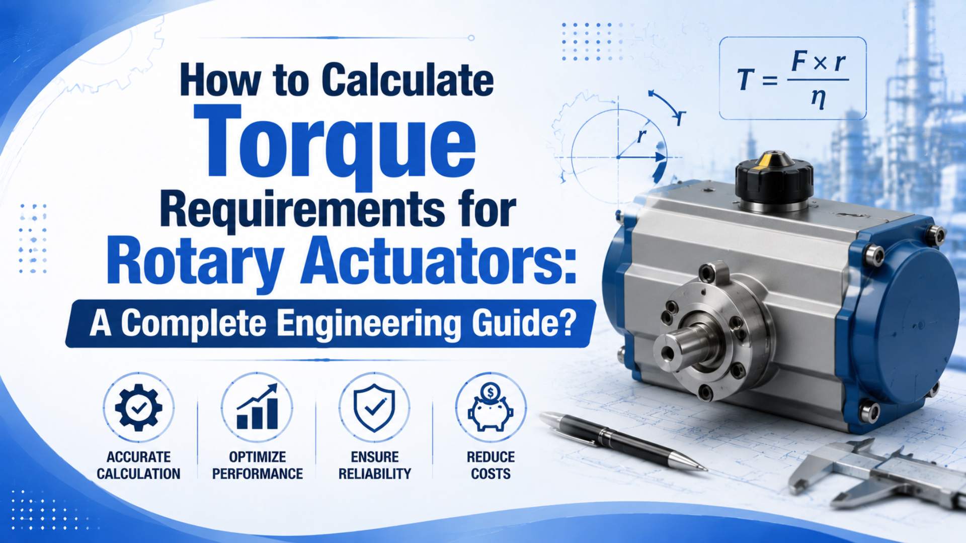
Torque requirements for rotary actuators come from the shaft load, gravity, friction, inertia, and the chosen motion profile. Parker defines demand torque from load, friction, and acceleration torque. Its PRO/PRN guide converts 90 degrees to 1.5708 radians before the dynamic calculation (Parker 0900P-4, accessed July 17, 2026; Parker PRO/PRN, accessed July 17, 2026).
The calculation is a torque ledger, not one shortcut. Keep each term visible, apply only a documented allowance, and compare the result with effective actuator torque at the lowest pressure present during motion. A separate pneumatic rotary actuator sizing guide covers shaft load, stopping energy, flow, mounting, and final model selection.
Key Takeaways
- Add load, gravity, friction, and acceleration torque as separate rows.
- Bray’s typical ball-valve curve shows running torque near 75% of break torque, but supplier data controls selection.
- Compare against effective catalog torque at moving pressure.
- Check stopping energy separately from torque.
What Belongs in a Rotary Actuator Torque Worksheet?
Parker separates demand torque into three components: load torque, friction torque, and acceleration torque. Its handbook treats cushion torque as a separate deceleration requirement, so a useful worksheet needs at least four calculation rows rather than one combined estimate (Parker 0900P-4, accessed July 17, 2026).
Begin with the load case, not the actuator catalog. Record the following values for each operating direction and any shaft angle where the load changes:
| Worksheet input | Symbol | Unit | Source |
|---|---|---|---|
| External force and perpendicular lever arm | F, r |
N, m | Drawing or measurement |
| Rotating mass and geometry | m, dimensions |
kg, m | CAD or weighing |
| Rotation angle | theta |
rad | Machine sequence |
| Acceleration time or motion profile | t_a |
s | Controls specification |
| Gravity orientation | phi |
degrees | Installation drawing |
| Breakaway and running friction | T_break, T_run |
N·m | Measurement or supplier data |
| Minimum inlet pressure during motion | P_min |
bar or MPa | Pressure trace at actuator |
| Required direction and fail position | n/a | n/a | Risk and process review |
Demand torque is the shaft torque needed to overcome the stated load and produce the required acceleration. Use one row for every independent source. For example, a spring, belt tension, seal drag, offset tool, process force, or cable bundle can change demand. Signs matter too: gravity can resist one direction and assist the return stroke.
The worksheet should show both magnitude and direction. A single positive total hides whether a load reverses through the stroke, which is exactly when the controlling torque can move from the start of travel to an intermediate angle.
How Do You Calculate Load and Gravity Torque?
NASA defines torque as force multiplied by the perpendicular distance from the pivot, and Parker applies the same T = F x l relationship in rotary-actuator selection. A 100 N force through a perpendicular 0.20 m arm therefore creates 20 N·m (NASA Glenn, accessed July 17, 2026; Parker PRO/PRN, accessed July 17, 2026).
For an external force:
Load torque = force x perpendicular distance
T_load = F x r_perpendicular
The perpendicular distance is the shortest distance from the shaft centerline to the force’s line of action. Using the physical arm length without the angle correction overstates torque whenever the force isn’t perpendicular.
For an offset mass rotating in a vertical plane:
Gravity torque = mass x 9.81 m/s^2 x center-of-gravity radius x sin(phi)
T_gravity = m x g x r_cg x sin(phi)
Gravity torque is zero when the center of gravity sits directly above or below the shaft. It reaches its largest magnitude when the center-of-gravity arm is horizontal. For a balanced table rotating around a vertical axis, gravity may add no rotary torque, although bearing and seal friction remain.
If CAD can calculate torque about the real shaft axis, use it. If not, split a complex assembly into masses, calculate each contribution, and add the signed values. Don’t replace a measured process force with the workpiece mass unless gravity is the only force in the load path.
How Do You Add Inertia and Acceleration Torque?
SMC’s low-speed rotary selection guide calculates inertial load from moment of inertia, rotation angle, and time, and instructs users to add the inertia of multiple load components. For CRQ2X/MSQX selection, motion slower than 2 seconds per 90 degrees is still evaluated using a 2-second value for the inertia check (SMC CRQ2X/MSQX guide, accessed July 17, 2026).
Acceleration torque follows the rigid-body relationship:
Acceleration torque = moment of inertia x angular acceleration
T_acc = J x alpha
Moment of inertia depends on where the mass sits, not only how much it weighs:
| Load shape about the stated axis | Moment of inertia |
|---|---|
Point mass at radius r |
J = m x r^2 |
| Solid disk about its center | J = 0.5 x m x r^2 |
| Thin ring about its center | J = m x r^2 |
| Slender rod about one end | J = m x L^2 / 3 |
| Rectangular plate about its center | J = m x (a^2 + b^2) / 12 |
Use the real motion profile to obtain alpha. If the controller or mechanism supplies acceleration time, use alpha = delta omega / t_a. For a symmetric triangular velocity profile that starts and ends at rest, with total move time t and angle theta:
alpha = 4 x theta / t^2
omega_max = 2 x theta / t
Don’t apply that triangular-profile equation to a move with a constant-speed plateau. A trapezoidal, S-curve, or mechanically cushioned move has a different acceleration history. The controls specification should state which profile the worksheet represents.
Moving mass closer to the shaft reduces J with the square of radius. Shifting a 2 kg component from 200 mm to 100 mm cuts its point-mass inertia from 0.080 to 0.020 kg·m², often saving more torque than a small pressure increase.
Why Must Breakaway and Running Torque Be Calculated Separately?
Bray’s 2025 ball-valve guide shows a typical floating-ball valve curve where running torque is about 75% of break torque and ending torque is about 90%. Those ratios describe the guide’s typical valve curve, not a universal friction law for every valve, bearing, seal, or rotary table (Bray Technical Bulletin 1005, 2025).
Breakaway torque is the peak resistance when motion begins after dwell; running torque is the resistance after movement starts. Bray’s typical floating-ball curve uses three distinct points, with break torque at 100%, running torque near 75%, and ending torque near 90%. These values explain why a valve cannot be represented by one friction coefficient, but they aren’t a substitute for supplier data. Seat design, differential pressure, media, temperature, dwell, and deposits can move every point on the curve. A machine joint needs the same separation when seal drag or bearing resistance changes after rest. Measure startup and running values in both directions instead of deriving one from the other. This keeps the maximum torque point visible after long dwell and through the complete stroke (Bray Technical Bulletin 1005, 2025).
For a machine load, measure both values when practical. Consider repeating the test after the longest expected dwell:
- Disconnect or safely isolate the actuator.
- Apply torque slowly at the shaft or driven coupling.
- Record the peak at first movement as breakaway torque.
- Record torque through the stroke in both directions.
- Repeat after the longest expected dwell and at the temperature limits.
For a ball, butterfly, or plug valve, request supplier torque data at the actual valve size, seat, differential pressure, media, temperature, and service condition. At minimum, compare break-to-open, running, end-to-open, break-to-close, running-to-close, and seating torque against the actuator curve.
The material-pair equation T = mu x N x r can help with a defined sliding interface whose normal load and effective radius are known. It is not a substitute for valve torque data or measured seal drag. Handbook friction coefficients can vary with finish, lubrication, pressure, temperature, wear, and dwell.
Which Design Factor Should You Apply?
Parker’s PRO/PRN guide uses a margin factor of 2 for resistance without load variation and 5 when the load varies. Those numbers belong to that product-family method; Parker’s broader handbook says design factors vary with the application and the designer’s knowledge (Parker PRO/PRN, accessed July 17, 2026; Parker 0900P-4, accessed July 17, 2026).
Don’t multiply unrelated factors for temperature, contamination, age, shock, and service life without checking the product method. Stacking 2.0 x 1.5 x 1.4 x 1.25 creates a 5.25 multiplier, but it doesn’t prove that the actuator will move smoothly, stop safely, or survive the shaft load.
Use this sequence instead:
- Calculate the nominal torque components from traceable inputs.
- Replace uncertain friction or process loads with measured worst-case values where possible.
- Apply the actuator or valve manufacturer’s specified factor.
- Add a project factor only when the responsible engineer can state which uncertainty it covers.
- Record the unrounded result and the selected catalog torque margin.
Keep the factor beside the component it protects. A variable process force may need a different allowance from a well-measured inertial load. Emergency movement, personnel risk, and fail-safe valve action also require the machine or process safety method, not a generic blog table.
Worked 90-Degree Torque Calculation
Parker lists 90 degrees as 1.5708 radians, while SMC treats angle and movement time as explicit inertia inputs. The example below rotates a 6 kg point load at a 0.20 m radius through 90 degrees in 0.80 seconds using a symmetric triangular velocity profile (Parker PRO/PRN, accessed July 17, 2026).
Assumptions:
| Input | Value |
|---|---|
| Point load | 6.0 kg |
| Radius from shaft | 0.20 m |
| Rotation | 90 degrees = 1.5708 rad |
| Total move time | 0.80 s |
| Measured running friction | 1.50 N·m |
| Gravity torque | 0 N·m, horizontal table |
| External process torque | 0 N·m |
| Documented project factor | 1.50 |
First calculate the point-mass inertia:
J = m x r^2
J = 6.0 x 0.20^2
J = 0.240 kg·m^2
Then calculate acceleration and acceleration torque:
alpha = 4 x theta / t^2
alpha = 4 x 1.5708 / 0.80^2
alpha = 9.82 rad/s^2

T_acc = J x alpha
T_acc = 0.240 x 9.82
T_acc = 2.36 N·m
Add the shaft-level components and apply the documented factor:
T_nominal = T_acc + T_friction + T_gravity + T_external
T_nominal = 2.36 + 1.50 + 0 + 0
T_nominal = 3.86 N·m

T_required = 3.86 x 1.50
T_required = 5.79 N·m effective output torque
The result is a catalog comparison requirement, not a part number. Compare 5.79 N·m with the actuator’s effective output curve at the minimum moving pressure, correct direction, and relevant shaft angle. Then check kinetic energy, shaft loading, rotation-time range, and stopping method in the broader rotary actuator sizing workflow.
If a calculation starts from ideal piston force or ideal vane area, mechanism efficiency may need to be included. If the catalog already publishes effective output torque, don’t reduce the catalog value and increase the required torque for the same efficiency loss. That counts the loss twice.
Catalog Comparison Uses Actual Torque Curves
A Festo DFPD-20 spring-return configuration lists 13.5 N·m at 0 degrees and 7.0 N·m at 90 degrees at nominal pressure. The two endpoint values differ by almost 2:1, which shows why one nameplate torque cannot represent every direction and shaft position (Festo DFPD-20-RP-90-RS55-F03, accessed July 17, 2026).
Effective actuator torque is the usable shaft output stated by the manufacturer for a particular pressure, direction, and position. Use the curve or table for the exact model and operating mode:
- Double-acting rack-and-pinion actuators may have nearly constant torque, but confirm the published curve.
- Spring-return actuators need separate air-start, air-end, spring-start, and spring-end comparisons.
- Scotch-yoke designs can have a deliberately non-linear torque profile.
- Vane and rotary-table models have product-specific effective torque and pressure limits.
Pressure at the regulator while idle isn’t the comparison pressure. Measure at the actuator inlet during the move, when the directional valve, tubing, fittings, flow controls, and exhaust path are carrying flow. If the measured pressure falls, review point-of-use pressure fluctuations and pneumatic flow-control valve sizing before selecting a larger actuator.
For process valves, overlay the required valve torque points on the actuator output curve. Festo also warns that actuator operating torque must not exceed the permissible ISO 5211 flange and coupling torque. A larger actuator can move the valve while overloading the stem, key, bracket, or coupling.
Record two margins: available torque / required torque and interface limit / available torque. The first catches an undersized actuator. The second catches the opposite problem, an actuator strong enough to damage the hardware it drives.
Five Errors That Invalidate an Otherwise Correct Result
SMC lists allowable kinetic energy from 0.00025 to 0.081 J across the CRQ2X sizes in its low-speed guide. That 324:1 range exists even within one product family, so a correct torque total cannot replace the model’s separate energy, timing, and load checks (SMC CRQ2X/MSQX guide, accessed July 17, 2026).
- Using total arm length instead of perpendicular distance. Torque depends on the force’s line of action. Recalculate it at every shaft angle that can become the worst case.
- Treating mass as inertia. Two 6 kg fixtures can demand very different acceleration torque when their mass sits at different radii.
- Using one friction number for startup and motion. Record breakaway and running values separately, especially after dwell or temperature change.
- Copying a safety-factor table without its product method. A large multiplier can hide bad input data and still miss kinetic energy, shaft load, or valve-stem limits.
- Comparing with torque at static supply pressure. Use effective model torque at the pressure measured while the actuator is moving.
The final worksheet should state every assumption, unit, sign convention, data source, and revision. If a load or friction term is estimated, mark it for commissioning verification. That turns the calculation into a maintenance baseline rather than a one-time sizing note.
What Do Engineers Ask About Rotary Actuator Torque?
Bray’s typical floating-ball curve contains three distinct torque levels: break at 100%, run near 75%, and ending near 90%. The questions below keep those valve-specific points separate from machine-load inertia, catalog output, and stopping-energy checks (Bray Technical Bulletin 1005, 2025).
What is the basic formula for rotary actuator torque?
For a static external force, use T = F x r_perpendicular. For a moving load, add gravity, friction, and J x alpha acceleration torque before applying the documented project or manufacturer factor. Parker defines demand torque from load, friction, and acceleration terms rather than one universal shortcut.
Is breakaway torque always twice running torque?
No. Bray’s typical floating-ball example places running torque near 75% of break torque, but that ratio belongs to the stated valve curve. Seal design, seat material, pressure, media, dwell, temperature, lubrication, and wear can change it. Use measured machine values or valve-supplier torque data.
Can actuator torque be scaled directly with pressure?
Only as a screening estimate when the manufacturer confirms the relationship for that model, direction, and position. Final selection uses the effective torque curve at moving pressure. Spring-return units need four endpoint checks because air-start, air-end, spring-start, and spring-end torque can differ substantially.
What safety factor should be used for rotary actuator torque?
Use the factor specified by the actuator, valve, machine standard, or responsible engineer. Parker’s PRO/PRN method uses factors of 2 and 5 for two defined resistance-load cases, but those figures aren’t universal. Document which uncertainty the chosen factor covers and avoid multiplying overlapping allowances.
Is the highest-torque actuator automatically the safest choice?
No. Parker requires the larger of demand torque and cushion torque, while SMC requires separate kinetic-energy and shaft-load checks. More output torque can overload a valve stem or ISO 5211 coupling. Choose a model that clears the required torque curve without exceeding mechanical interface limits.
Torque calculation ends with a curve comparison, not a rounded number. Keep the torque ledger with the machine drawing, pressure trace, motion profile, valve data, and catalog revision. For mechanism selection, see rack-and-pinion versus vane rotary actuators. For an application review, send the completed worksheet through the technical contact page.
Source Notes
Six first-party technical sources support the calculation method: NASA Glenn, two Parker guides, one SMC model-selection catalog, Bray’s 2025 valve bulletin, and a Festo product page. Each claim above stays within its source’s stated product or application boundary. Editorial ownership and engineering context are described on the About page.
-
NASA Glenn, Torque. Force, perpendicular distance, and torque relationship. Retrieved July 17, 2026.
-
Parker Pneumatic Actuator Products, Catalog 0900P-4. Demand, load, friction, acceleration, cushion torque, and kinetic-energy definitions. Retrieved July 17, 2026.
-
Parker PRO/PRN Pneumatic Rotary Actuators. Product-family torque and motion calculation method. Retrieved July 17, 2026.
-
SMC CRQ2X/MSQX Low-Speed Rotary Actuator Guide. Load types, inertia, effective torque, kinetic energy, and stable rotation-time limits. Retrieved July 17, 2026.
-
Bray Technical Bulletin 1005, Actuator Selection Guide for Ball Valves. Break, running, and ending valve-torque curves. Published 2025; retrieved July 17, 2026.
-
Festo DFPD-20-RP-90-RS55-F03. Direction- and angle-dependent spring-return torque data and ISO 5211 interface note. Retrieved July 17, 2026.