


Clean-room pneumatic grippers can improve electronics manufacturing when they reduce contamination risk without sacrificing secure, repeatable handling. The improvement doesn’t come from an “oil-free” label alone. It comes from matching a tested gripper configuration to the room class, product sensitivity, mounting position, motion profile, compressed-air quality, and cleaning process.
This guide stays with jaw grippers and their end-of-arm tooling. It does not cover the complete cleanroom pneumatic chain. If the jaw mechanism is still undecided, compare parallel, angular, and other pneumatic gripper types before applying the cleanroom checks below.
FDA guidance associates ISO 5 with no more than 3,520 particles/m³ at 0.5 µm and larger in an operating critical area (FDA Aseptic Processing Guidance, 2004). That limit describes the environment. A gripper still needs model-specific evidence and an installed test. For the system-wide selection boundary, use the broader guide to Class 100 cleanroom pneumatic components.
Key Takeaways
- ISO 5 allows 3,520 particles/m³ at 0.5 µm and larger in FDA guidance.
- A room class doesn’t certify a gripper.
- Size grip force from mass, acceleration, friction, jaw count, and safety factor.
- Qualify contamination and motion together on the installed machine.
That distinction matters.
What Does “Clean-Room Certified” Actually Mean for a Gripper?
ISO 14644-14:2026 evaluates equipment emissions across particle sizes from 0.1 µm to 5 µm and above. “Clean-room certified” should mean a named gripper configuration was assessed under fully stated operating conditions, sampling geometry, background concentration, and particle sizes. A room classification alone cannot certify the component (ISO 14644-14, 2026).
ISO 14644-1 classifies airborne particle concentration in a cleanroom or clean zone. It explicitly does not characterize the chemical, physical, radiological, or viable nature of those particles (ISO 14644-1, 2015). Part 14 supplies an equipment-suitability method, but excludes cleanability, material selection, biocontamination, electrostatic properties, and process-performance optimization. One certificate can’t close all of those gaps.
A useful claim names the evidence boundary.
Equipment suitability is a test-supported statement that a named configuration meets a defined particle or chemical limit under recorded conditions.
| Claim element | Evidence that makes it useful |
|---|---|
| Exact configuration | Model, size, fingers, seals, grease, sensors, fittings, and revision |
| Operating state | Pressure, speed, load, acceleration, orientation, cycle count, and run-in condition |
| Particle test | Particle sizes, counter, probe position, chamber, background, duration, and measured result |
| Chemical test | Target substances, temperature, conditioning time, detection limits, and result |
| Installation boundary | Position relative to exposed product, airflow direction, exhaust route, and cable routing |
| Process boundary | Cleaning chemistry, contact time, ESD requirements, product-contact status, and acceptance limit |
The room class and equipment particle result are separate acceptance budgets. Chemical emissions form another. Product handling adds a fourth. A gripper can pass one and fail another. Keeping them separate prevents a low-particle claim from being mistaken for cleanability or ESD safety. It also keeps handling damage visible.
In our experience, the fastest way to expose a weak cleanroom claim is to ask for the exact tested part number and installation position. Then request the sampling geometry and operating envelope. Vague claims become clear once those four fields must be completed.
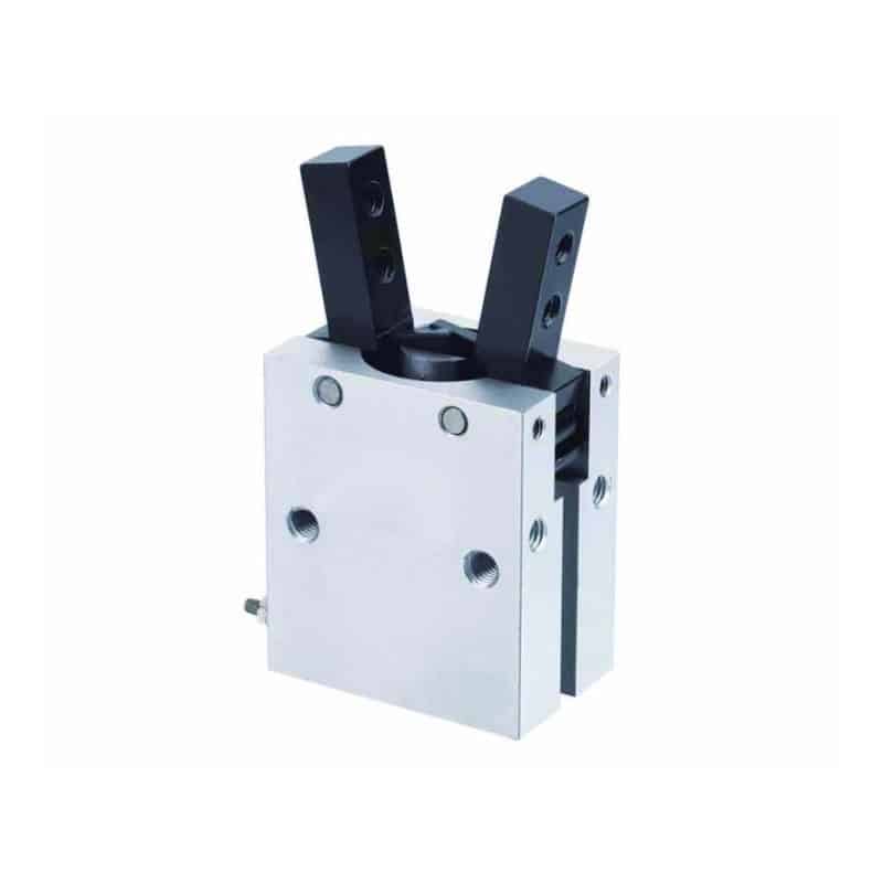
Where Does Gripper Contamination Come From?
SMC’s MHZ2 catalog identifies two clean configurations, prefixes 11 and 22. It assigns separate grease and material conditions, showing why contamination risk depends on the exact seals, guides, lubricant, exhaust, fingers, cables, and service state (SMC MHZ2 Clean Series, accessed 2026). Generic labels can’t show that.
Start at the moving interfaces.
Trace each path from the exposed component back through the end-of-arm tooling. Particle generation at the jaw guide may be obvious. Exhaust air can disturb local airflow. Cable jackets can shed. An unsuitable cleaning agent may damage a seal without causing an immediate fault. For example, performance after extended cycling may differ from a new-sample result.
| Contamination path | What can release or transfer contamination | What to verify |
|---|---|---|
| Fingers and contact pads | Wear debris, adhesive residue, plating particles, trapped product fragments | Pad material, contact pressure, replaceability, cleaning method, and inspection limit |
| Guides and bearings | Sliding wear, misalignment, impact, grease migration | Load moment, finger length, speed, backlash, lubricant, and particle data |
| Seals and internal grease | Seal debris, oil mist, volatile or condensable compounds | Exact seal and grease specification, temperature, pressure, and emission evidence |
| Ports and exhaust | Oil, water, pipe debris, silencer fibres, disturbed airflow | Point-of-use air quality, remote exhaust, filter rating, backpressure, and leakage |
| Sensors and cables | Jacket wear, heat, adhesive, connector debris | Cable material, flex radius, switch location, cleanability, and packaging |
| Service work | Tools, replacement parts, grease quantity, open packaging | Controlled procedure, approved consumables, traceability, and requalification trigger |
ISO 14644-15:2026 covers equipment and material suitability by airborne chemical concentration. It excludes cleaning-agent compatibility and cleanability. Biocontamination, process-specific requirements, and equipment design also remain outside its scope (ISO 14644-15, 2026). A low-particle result therefore can’t approve every grease or elastomer. Adhesives and cables still need process-specific review.
From our application work, we’ve found that the exhaust path and service state are the two fields most likely to be missing from an otherwise detailed component comparison. Both can change after the original sample test.
“Non-lube” is another boundary that needs careful wording. It usually means the actuator doesn’t require routine external lubrication, not that it contains no factory grease or produces no contamination. The non-lube cylinder cleanroom guide explains the same distinction for linear actuators.
How Do You Select Grip Force Without Damaging Electronics?
NIST defines standard acceleration as 9.80665 m/s². That value supplies the gravity term in a friction-grip calculation, but the selected force must also cover machine acceleration, orientation, friction uncertainty, and a justified safety factor without exceeding the part’s damage limit (NIST Guide to the SI, accessed 2026).
Force is a window, not a target.
For a vertical friction grip with equal load sharing, estimate the minimum normal force per jaw with:
Fjaw ≥ m(g + a)S / (μn)
Where:
- Fjaw is required normal force per jaw in newtons.
- m is moving mass in kilograms, including any carrier held by the jaws.
- g is 9.80665 m/s² for a standard-gravity estimate.
- a is the worst acceleration component acting in the slip direction.
- S is a safety factor justified by friction and process uncertainty.
- μ is the tested friction coefficient at the actual contact surfaces.
- n is the number of jaws contributing friction force.
Grip-force window means the verified range between the minimum force that prevents slip and the maximum force that avoids unacceptable part damage or deformation.
Consider a 0.20 kg assembly moving vertically at 5 m/s² with two jaws, a tested friction coefficient of 0.30, and a safety factor of 2. The screening result is about 9.9 N per jaw. That is the lower boundary. The upper boundary must come from contact-pressure, bending, component-clearance, and damage testing on representative parts.
Don’t substitute catalog closing force blindly. Catalog force can change with pressure and gripping-point distance, while long fingers add moment and deflection. Check whether the quoted value is per jaw or total, and whether it applies during opening or closing. Then test the lowest pressure that maintains the required margin through acceleration, emergency stop, part tolerance, pad wear, and supply-pressure variation.
Force isn’t the only motion criterion. One clean-series MHZ2 catalog lists ±0.01 mm repeatability and a maximum frequency of 180 cycles per minute for that family, but those values don’t define acceptable stress on a fragile component (SMC MHZ2 Clean Series, accessed 2026). Confirm jaw position, part compliance, approach speed, dwell time, and release behaviour separately.
Qualify the Installed End-of-Arm Tooling
SMC’s clean-series method samples for 30 minutes at 28.3 × 10⁻³ m³/min on an ISO Class 5-equivalent bench and applies the 95% upper confidence limit. Installed tooling still needs qualification at its actual speed, load, orientation, exhaust routing, and background concentration (SMC Clean Series, accessed 2026).
A supplier chamber test is valuable, but it is a controlled comparison. Your machine may add longer fingers and side load. It can also introduce higher acceleration, a different cable carrier, nearby valve exhaust, or product particles. The probe may sit in another airflow path. Would a catalog test capture a remote exhaust tube pointing across an exposed wafer? Only an installed assessment can answer that.
Test the machine, not just the component.
Use a staged qualification rather than one pass/fail count:
| Stage | Operating condition | Record |
|---|---|---|
| Background | Machine stopped, gripper installed | Room state, airflow, probe location, particle sizes, and background concentration |
| Run-in | New fingers, seals, cables, and fittings | Cycle count, speed, pressure, load, particle trend, leakage, and visible residue |
| Normal production | Representative parts and recipe | Particle result, grip faults, part damage, repeatability, pressure, and cycle time |
| Worst credible motion | Maximum approved speed, acceleration, load, and finger moment | Slip margin, impact, deflection, particle peaks, exhaust effect, and recovery |
| Maintenance state | Before service and after approved service | Wear, grease condition, replaced parts, cleaning state, and requalification result |
Qualify cleanliness and handling quality in the same run. A slower motion profile may reduce particles, yet miss the takt-time target. Higher force can prevent drops. It can also mark a connector housing. Remote exhaust protects the product only if added backpressure doesn’t delay release. One test matrix exposes these interactions before production acceptance.
The same rule applies to motion. Compare gripper requirements with the guide to pneumatics in automated PCB assembly, then keep the component class and machine recipe inside one evidence boundary.
What Maintenance Preserves Clean-Room Performance?
ISO 14644-13:2026 separates surface cleanliness by particle concentration and surface cleanliness by chemical concentration. Maintenance should therefore be triggered by measured particle trends, residue risk, wear, leakage, and service events, not by a universal daily, weekly, or monthly calendar (ISO 14644-13, 2026).
Build the maintenance plan from failure mechanisms and evidence. A visual check can find damaged fingers or cable jackets, but it cannot quantify a rising particle trend. A pressure or leak check can find pneumatic deterioration, yet it says little about chemical residue. Cleaning can restore a surface, or it can swell a seal and remove a qualified lubricant. Each task needs its own acceptance criterion.
Calendar intervals are only placeholders.
| Trigger | Required response | Requalification scope |
|---|---|---|
| Particle trend crosses an alert limit | Inspect fingers, guides, seals, impact, alignment, exhaust, and nearby moving parts | Repeat background and operating particle measurements |
| Grip margin or repeatability deteriorates | Check pressure, leakage, friction pads, jaw play, finger moment, and part variation | Repeat force, slip, damage, and motion tests |
| Seal, grease, finger, cable, or fitting changes | Confirm approved part number, material, quantity, packaging, and assembly method | Repeat the affected particle, chemical, and handling tests |
| Cleaning chemistry or contact time changes | Run material-compatibility and residue checks | Reassess surface cleanliness and operating performance |
| Tooling moves relative to the product or airflow | Review probe position, exhaust direction, release paths, and product exposure | Repeat installed qualification in the new position |
ISO 14644-13 gives general guidance for evaluating cleaning methods. Detailed procedures and damage mechanisms remain outside its scope, as do microbiology and process-specific chemistry. Record the exact agent, concentration, and temperature. Add contact time, wiping material, cycle count, and inspected failure modes. “IPA compatible” isn’t enough when repeated exposure is unknown.
Keep service work controlled. Open parts only in the approved environment. Use traceable replacement kits. Limit grease to the specified type and quantity, then document the post-service result. For related upstream risks, review how to prevent contamination in pneumatic control valves.
What Evidence Should You Request Before Purchase?
ISO 8573-1 defines three principal compressed-air contaminant groups: particles plus water and oil. State a class for each group at the point of use. Then request model-specific evidence for particle emissions and materials. Include grease, cleaning, packaging and grip performance in the same RFQ (ISO 8573-1, 2010).
Point-of-use air quality is the specified or measured compressed-air condition where air enters the gripper or its relevant valve and regulator connection.
Send suppliers the real application envelope. A request that says only “ISO 5 gripper” invites incompatible assumptions. State the gripper position and exposed product first. Add the relevant particle sizes. Describe jaw motion and the contamination types that can damage the product.
Visible gaps are actionable.
| RFQ field | Information to provide | Evidence to request |
|---|---|---|
| Cleanliness target | Room state, ISO class, particle sizes, sampling position, chemical limits, and background | Model-specific report, configuration, method, raw result, uncertainty, and test date |
| Installation | Drawing, airflow, distance from product, valve location, exhaust route, and cable path | Tested orientation, probe position, relief or suction arrangement, and allowed plumbing |
| Motion and load | Part mass, acceleration, cycle time, finger length, moment, pressure, and emergency-stop case | Force curve, gripping-point limits, repeatability, frequency, leakage, and clean-series restrictions |
| Product contact | Contact material, pressure limit, ESD rule, sensitive surfaces, and allowed residue | Finger and pad material, finish, traceability, cleanability, and compatibility data |
| Air supply | Point-of-use particle, water, and oil classes; pressure and dew point | Filtration, regulator, tubing, lubrication, and measurement requirements |
| Maintenance | Access, allowed tools, replacement policy, cleaning chemistry, and planned monitoring | Seal kit, grease specification, work instruction, packaging, shelf life, and requalification triggers |
Use the ISO compressed-air quality guide to translate the three ISO 8573-1 groups into a point-of-use specification. When oil aerosol becomes the limiting risk, the coalescing-filter guide explains the boundary of filtration.
Use three labels for missing supplier evidence. Mark an absent result as not tested. Use not applicable only with a documented reason. Choose requires installed qualification when the machine must close the evidence gap. These labels are more useful than an unsupported compliance promise because each one points to a different decision.
Our team found that these three labels make supplier replies easier to compare because a missing result can no longer hide behind a general product-family statement.
Conclusion: Better Evidence Improves Quality and Efficiency
ISO updated Parts 13 and 14 in February 2026, followed by Part 15 in May. These documents distinguish surface cleaning, airborne particle emission, and airborne chemical suitability. Electronics quality improves when those boundaries are combined with grip-force calculations and installed tests (ISO 14644-13, 2026; ISO 14644-14, 2026; ISO 14644-15, 2026).
The practical sequence is straightforward. Define the product risk, trace every contamination path, calculate the grip-force window, compare exact model evidence, and qualify the installed end-of-arm tooling. Continue monitoring after service or process changes. That approach reduces contamination surprises and handling faults without making performance claims that the available evidence cannot support.
FAQs About Clean-Room Certified Pneumatic Grippers
FDA’s ISO 5 reference limit is 3,520 particles/m³ at 0.5 µm and larger during operation. That number classifies the critical environment. It does not certify the gripper. The answers below therefore keep five decisions separate: room classification, equipment evidence, force setting, cleaning, and requalification (FDA Aseptic Processing Guidance, 2004).
Does ISO Class 5 certify a pneumatic gripper?
No. ISO 14644-1 classifies airborne particle concentration in a cleanroom or clean zone. ISO 14644-14:2026 supplies the equipment-suitability method across particle sizes from 0.1 µm to 5 µm and above. Ask for the exact gripper and operating condition. Record the test chamber, sampling geometry and particle sizes.
Is an oil-free or non-lube gripper automatically cleanroom suitable?
No. ISO 8573-1 separates compressed-air purity into particles plus water and oil. A gripper can still contain factory grease and seals as well as adhesives or cable materials. Verify the exact configuration and grease. Check its exhaust route and chemical-emission risk. Confirm cleaning compatibility and particle performance separately.
How much gripping force should I use for a delicate electronic part?
No universal force range exists. Calculate the minimum per-jaw force from mass and gravity plus acceleration. Include measured friction, jaw count and a justified safety factor. Establish the maximum through contact-pressure and bending tests. Then check clearance, appearance and function. Use only the verified window between slip and damage.
How often should a cleanroom gripper be serviced?
Use model instructions plus site trend data, not a generic calendar. Track cycle count and particle concentration. Watch leakage, jaw play and repeatability. Record grip margin along with cleaning exposure and service history. Inspect parts at documented limits. Requalify affected functions after changes to seals, grease, fingers, cables, or fittings.
Can an existing pneumatic station be upgraded with a cleanroom gripper?
Yes, if the surrounding system is included in the review. Confirm point-of-use air quality, valve and exhaust location, tubing, fittings, cable carrier, pressure stability, cleaning access, airflow, and product exposure. Recalculate grip force and repeat installed qualification because a clean gripper cannot correct contamination introduced elsewhere in the station.
Source Notes and Retrieval Dates
-
ISO 14644-1:2015, airborne particle classification scope and exclusions. Retrieved 2026-07-17.
-
ISO 14644-13:2026, cleaning surfaces to specified particle and chemical cleanliness levels. Retrieved 2026-07-17.
-
ISO 14644-14:2026, equipment suitability by airborne particle concentration and scope exclusions. Retrieved 2026-07-17.
-
ISO 14644-15:2026, equipment and material suitability by airborne chemical concentration. Retrieved 2026-07-17.
-
ISO 8573-1:2010, compressed-air particles, water, oil, and additional contaminants. Retrieved 2026-07-17.
-
FDA Aseptic Processing Guidance, Class 100 and ISO 5 terminology and the 3,520 particles/m³ limit. Retrieved 2026-07-17.
-
SMC MHZ2 Clean Series, clean configurations, grease, operating limits, and repeatability data. Retrieved 2026-07-17.
-
SMC Clean Series evaluation method, sampling flow, interval, chamber, and confidence-limit method. Retrieved 2026-07-17.
-
NIST Guide to the SI, standard acceleration of free fall. Retrieved 2026-07-17.