

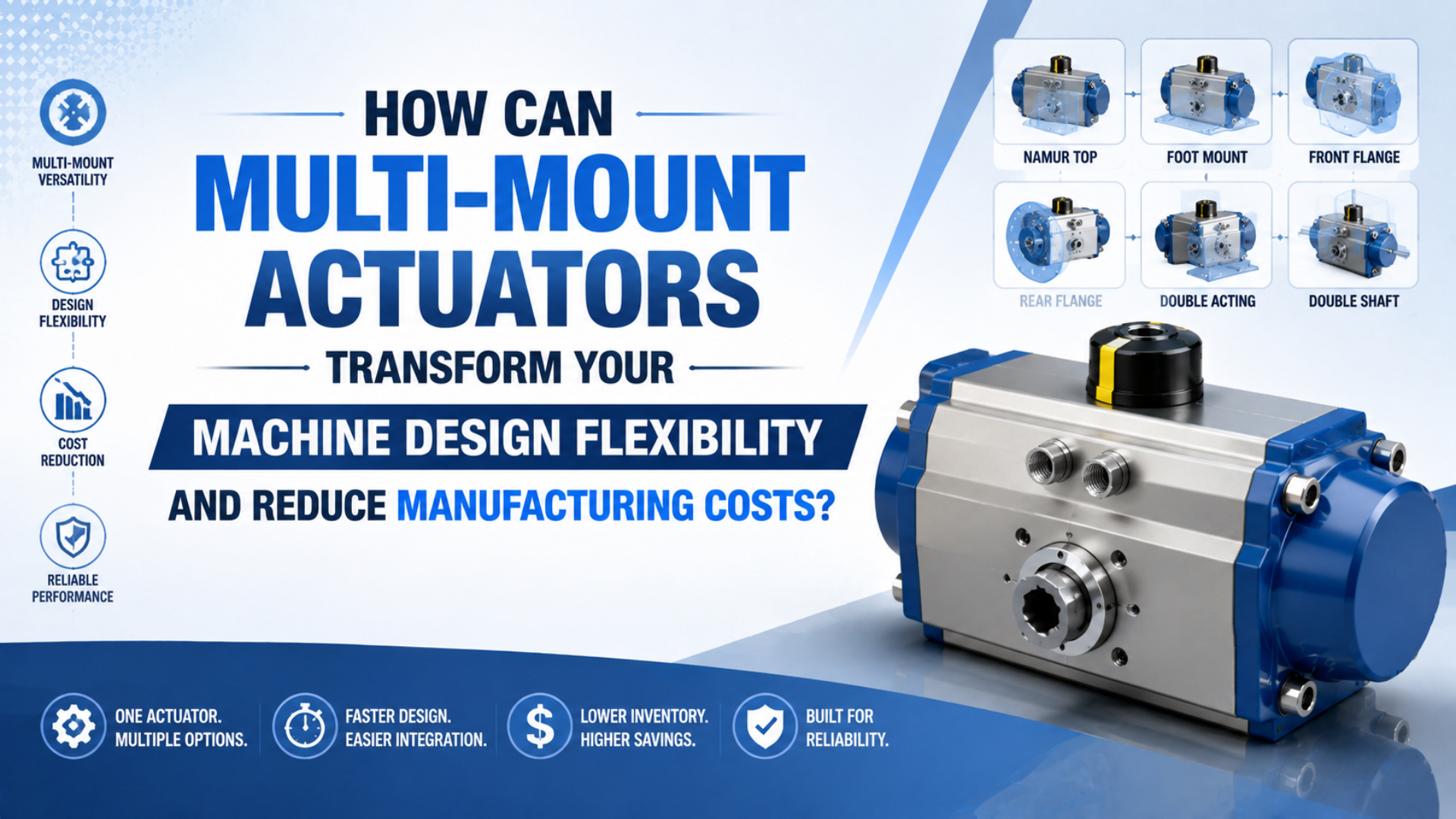
Multi-mount actuators can reduce redesign work when one proven cylinder family accepts several documented mounting kits. The useful flexibility comes from a controlled mechanical interface, not from treating every bracket as interchangeable. Machine builders get the most value when they reuse the cylinder body while validating each load path, clearance envelope, and accessory combination.
This is a machine-platform decision. A facility-wide pneumatic cylinder standardization program has a broader job: it governs installed assets, spares, supplier risk, and exceptions across many machines.
Key Takeaways
- ISO 15552 covers detachable-mount cylinders from 32 to 320 mm at up to 10 bar.
- Reuse the cylinder body only when the mount kit, load path, ports, sensors, and cushioning remain compatible.
- Measure savings from your own engineering hours, active SKUs, brackets, spares, and validation work.
Publisher information is available on the About Us page. Send technical questions or correction requests through Contact.
What Is a Multi-Mount Actuator in Practical Machine Design?
ISO 15552 defines detachable mounting and accessory dimensions for pneumatic cylinders from 32 to 320 mm bore at a maximum rated pressure of 1,000 kPa, or 10 bar. That scope supports reusable interfaces, but it does not promise that every mount, option, or operating duty can share one body (ISO 15552:2018, confirmed 2025).
A multi-mount actuator is best understood as a cylinder platform with a controlled set of compatible attachment points and mounting accessories. Depending on the family, those accessories may include feet, front or rear flanges, clevis brackets, trunnion flanges, swivel supports, rod clevises, and spherical rod eyes.
The word “multi” describes configuration choices. It doesn’t mean the machine can rotate the cylinder to any angle after installation, and it doesn’t remove the need to check how force enters the frame. A flange carrying axial thrust, a foot mount carrying an offset reaction, and a clevis following an arc create different stresses even when the bore and stroke are unchanged.
What is the practical design advantage? The machine builder can freeze one cylinder envelope, sensor concept, port standard, and service procedure, then release several approved mount kits for different machine variants. That approach is narrower than cross-supplier ISO 15552 cylinder interchangeability, which also requires drawing comparison and first-article evidence.
The most useful boundary is simple: standardize the body, configure the interface, and validate the application. If a new mount changes the required rod, cushioning, seal package, or cylinder construction, it is no longer a bracket-only variation.
Mount Selection by Load Path
Parker groups pivot mounting into six documented variants, including two clevis types, a spherical bearing, and three trunnion positions. It also states that cap-end mounts suit major push loads while head-end mounts suit major pull loads. Select the mount from force direction and motion geometry, not from available bolt holes (Parker 0900P-6, 2025).
| Mount family | Motion relationship | Main load-path rule | Machine detail to control |
|---|---|---|---|
| Front or rear flange | Fixed, straight-line motion | Keep the major force close to the cylinder centerline; choose head or cap end from pull or push duty | Flat pilot surface, bolt pattern, flange bending, service access |
| Foot or side mount | Fixed, straight-line motion | Offset between mounting plane and force centerline creates a turning moment | Guided load, shear key or dowel strategy, thermal expansion |
| Rear clevis | Pivoting in one plane | Cylinder and rod end must pivot freely through the full arc | Parallel pin axes, pin shear, hose movement, extended-rod stability |
| Trunnion | Pivoting in one plane | Support both trunnion pins in shear and minimize bending | Coaxial bearing blocks, shoulder clearance, defined trunnion position |
| Spherical pivot | Limited angular deviation | Use only within the supplier’s angular and pressure limits | Bearing rating, misalignment angle, matching rod-end joint |
Load path is the route force takes from the piston through the cylinder mount and into the machine frame. Parker warns that side-mounted cylinders should use a shear key or dowel strategy to resist the major load, but they should not be rigidly keyed at both ends. The cylinder must remain free to expand and contract as temperature and pressure change.
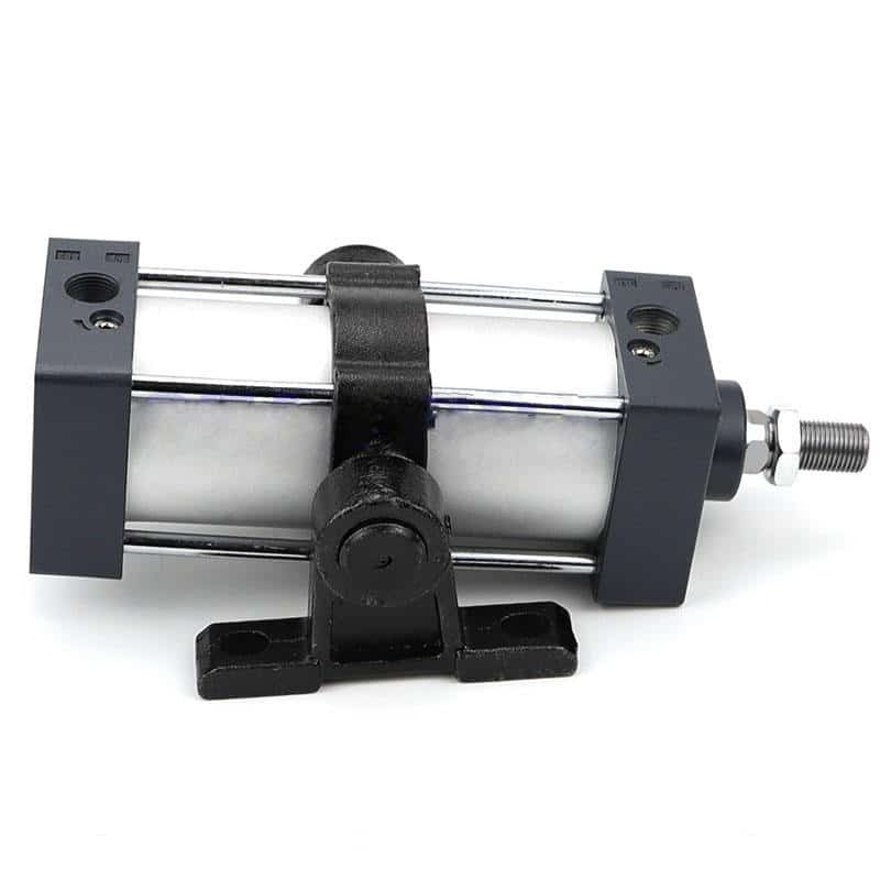
A trunnion deserves its own geometry review. Parker specifies bearing blocks at least as long as the trunnion pins and recommends supports close to the shoulder faces. The trunnion mount cylinder application guide covers pin support, force angle, rod stability, and commissioning without turning this article into another trunnion primer.
Side load remains a separate problem. A new bracket cannot turn an unguided cylinder rod into a linear bearing. Check the machine’s guide arrangement against the side-loading failure mechanisms before approving the platform.
Can One Cylinder Body Support Several Mounting Configurations?
Festo’s April 2026 DSBC data lists seven bores from 32 to 125 mm, strokes from 1 to 2,800 mm, and a peripheral system that includes foot, flange, trunnion, swivel, and clevis attachments. The same document also records combination restrictions, proving that a modular catalogue still needs option-by-option compatibility checks (Festo DSBC, 2026).
Yes, one body can support several configurations when the manufacturer has designed and rated the relevant interfaces. The drawing and part-code system must answer five questions:
- Is the mounting accessory approved for the selected bore and cylinder variant?
- Can it attach to the bearing cap, end cap, profile barrel, or only one of those locations?
- Does it conflict with bellows, locks, extended rods, sensors, valve kits, or guides?
- Does the new orientation preserve port, cushion-adjuster, and sensor access?
- Is the rod-end connection compatible with the new motion path?
Festo, for example, lists a trunnion flange kit that can mount along the profile barrel, while other foot and flange accessories attach to specified end caps. Its matrix also shows exclusions between certain mounts and bellows or locking variants. The cylinder name alone can’t resolve those combinations.
An interface ownership matrix keeps the decision auditable:
| Interface | Controlled by | Evidence required |
|---|---|---|
| Basic cylinder envelope | ISO family and supplier drawing | Current standard plus configured drawing |
| Mount-to-cylinder connection | Cylinder manufacturer | Accessory code, bore range, location, fasteners |
| Mount-to-machine connection | Machine designer | Frame drawing, locating method, bolt and key design |
| Rod-end joint | Supplier and linkage designer | Thread, pin, bearing, travel arc, angular freedom |
| Functional acceptance | Machine owner | Force, timing, leakage, cushioning, sensor, and safety tests |
Could purchasing substitute a similar-looking bracket? Only after the dimensions, material, rating, fasteners, locating features, and supplier approval are matched. An accessory that fits the bolt pattern can still place the pivot at the wrong location or introduce a weaker pin.
Where Does Multi-Mount Design Reduce Cost?
A 2025 engineer-to-order machinery study found approximately 29% potential engineering-hour reduction in one high-impact subsystem after reducing module variants. The authors present that result as case-specific and note that inventory and lead-time effects need further modeling. Use the finding as evidence for measurement, not as a universal actuator savings rate (Grønvald et al., 2025).
Multi-mount design saves money only when it removes repeated work or unnecessary parts without shifting cost into brackets, validation, or downtime. Build the business case from your own baseline:
| Cost driver | Baseline to record | Multi-mount comparison |
|---|---|---|
| Engineering | Hours spent selecting, drawing, checking, and documenting each variant | Hours to release the common body plus each mount kit |
| Purchased parts | Active cylinder, bracket, pin, sensor, and fitting SKUs | Common body SKUs plus approved accessory SKUs |
| Fabrication | Custom brackets, machining, welding, coating, and inspection | Standard kits plus any remaining machine adapter plate |
| Assembly | Installation steps, adjustment, alignment, and test time | Variant-specific work instructions and verification time |
| Spares | Stock value, emergency purchases, obsolescence, and wrong-part events | Shared body coverage and mount-specific spare strategy |
| Change control | Drawing revisions, BOM updates, software or sensor changes | Controlled configuration matrix and release records |
Use this project-level comparison instead of a borrowed percentage:
Lifecycle cost is the sum of cylinder bodies, mount kits, custom fabrication, engineering hours, validation, inventory carrying cost, and expected downtime exposure.
A platform wins when that total falls across the planned production volume and service life. A cheaper body can lose if every variant needs a custom adapter. A slightly higher-cost body can win when it removes repeated drawings, simplifies spares, and keeps sensors and ports consistent.
What should the design review reject? Any business case that counts fewer cylinder SKUs but ignores the new bracket SKUs, duplicate pins, variant-specific work instructions, or qualification tests. For a plant-level rollout beyond one product platform, use the separate cylinder standardization framework.
A Five-Step Multi-Mount Platform Workflow
ISO 15552 spans 11 nominal bore sizes from 32 through 320 mm, yet dimensional range alone cannot define a machine platform. ISO 10099 separately specifies final functional tests and acceptance criteria for double-acting single-rod cylinders. Treat mechanical fit and functional release as two evidence layers (ISO 15552, confirmed 2025; ISO 10099, confirmed 2023).
1. Freeze the application envelope
Record actual moving pressure, required extension and retraction force, stroke, target time, cycles, load direction, side load, speed, cushioning demand, environment, safety function, and available space. If those inputs vary by machine model, show the minimum and maximum for each variant.
2. Select the common body deliberately
Choose the cylinder family only after every planned variant fits its bore, stroke, pressure, temperature, seal, sensing, cushioning, and rod-stability limits. Use the pressure-and-area force guide for the basic thrust calculation, then apply the supplier’s allowances and application checks.
3. Build the mounting configuration matrix
Give each released configuration a code. List the body part number, mount kit, rod-end hardware, locating features, fastener specification, orientation, port direction, sensor position, and machine models that may use it. Include prohibited combinations in the same document. Silence is not an approval.
4. Validate every load path
Run a drawing review and physical test for each mount family. Confirm full-stroke clearance, free pivoting, alignment, fastener access, hose movement, sensor operation, cushion behavior, leakage, and actual cycle time. One successful foot-mounted test doesn’t release a clevis or trunnion variant.
5. Release the configuration under change control
Freeze the accepted drawings, supplier codes, inspection points, torque requirements, and machine test record. If the supplier revises the body or accessory, reopen the affected checks. That’s how a flexible platform stays controlled after the original designer moves to another project.
When Should You Keep a Dedicated Cylinder?
ISO 21287 covers compact cylinders from 20 to 100 mm bore at up to 10 bar, but its scope excludes adjustable cushioning and restricts use to applications that don’t require it. This is a useful reminder: a standard mounting envelope cannot override a motion or energy requirement that needs a different cylinder architecture (ISO 21287:2004, confirmed 2023).
Keep a dedicated cylinder or actuator when any of these conditions changes the body rather than the bracket:
- The load needs an integrated guide, anti-rotation feature, or external carriage.
- A compact envelope, long stroke, or unusual installed length drives the architecture.
- The application needs adjustable cushioning, external shock absorbers, or a higher energy rating.
- Washdown, chemicals, welding spatter, low temperature, or high temperature require different seals and materials.
- A safety function needs a certified lock, monitored valve architecture, or defined safe position.
- The motion leaves one plane and requires a spherical joint, guided linkage, or different kinematic arrangement.
- Port location, valve integration, or sensor access cannot remain serviceable with the proposed mount.
Would an adapter plate solve the problem? Sometimes. For example, a rigid machined plate can preserve a validated cylinder body across two frame patterns. It should not create a new moment, block adjustment points, or make alignment depend on thin sheet metal. The adapter needs its own drawing, material, locating features, and inspection criteria.
Rodless actuators deserve another boundary. Their carriage, guide, and mounting behavior differ from a detachable-mount tie-rod cylinder. Use the rodless cylinder mounting guide when the machine needs a long guided stroke rather than a standard piston rod and accessory bracket.
Multi-Mount Actuator RFQ Checklist
Festo’s 2026 DSBC modular range includes temperature variants from -40 to +80°C and from 0 to +150°C, plus several cushioning, rod, locking, and corrosion options. A useful RFQ must therefore identify the configured body and application limits before it asks for several mounting kits (Festo DSBC, 2026).
Send one controlled data package with the following fields:
| RFQ field | What to provide | Why it matters |
|---|---|---|
| Machine variants | Model names, annual volume, service locations | Defines the platform boundary and spare strategy |
| Cylinder duty | Bore, stroke, rod, pressure during motion, load, speed, cycles | Confirms that one body covers every variant |
| Mount configurations | Foot, flange, clevis, trunnion, or other approved style | Lets the supplier quote exact accessory codes |
| Load path | Push or pull, fixed or pivoting, side load, moment, shock | Determines mount location, keys, pins, and rod checks |
| Geometry | Installed length, pivot coordinates, full travel arc, clearances | Prevents a bracket-only selection from breaking the mechanism |
| Interfaces | Ports, fittings, rod end, sensors, cables, cushion access | Protects installation and serviceability |
| Environment | Temperature, washdown, corrosion, dust, chemicals | Selects seals, materials, scraper, bellows, and coating |
| Validation | Drawing review, first article, leakage, timing, impact, sensor test | Defines acceptance before production release |
| Change control | Required notice, drawing revision, traceability | Keeps future deliveries equivalent to the approved configuration |
Ask the supplier to return an option-specific drawing and a configuration matrix, not just a family brochure. The drawing should identify which interfaces follow a standard and which remain supplier-controlled. If the project includes cross-supplier sourcing, apply the stricter ISO 15552 interchangeability workflow.
Calculator tools are intentionally omitted. Force, rod buckling, and cushion energy can matter inside the application review, but none of the current calculators determines mount reaction, bracket strength, accessory compatibility, or total platform cost. A prominent calculator card would suggest a completeness the calculation cannot provide.
What Do Engineers Ask About Multi-Mount Actuators?
ISO 15552 covers a 32-320 mm, 10 bar detachable-mount series, while Festo’s 2026 DSBC catalogue shows that real product families add option-specific restrictions. In practice, mounting flexibility is valuable only inside a documented compatibility and validation envelope (ISO 15552; Festo DSBC).
Does multi-mount mean the cylinder can rotate through 360 degrees?
No. Parker describes clevis and trunnion arrangements for curved rod travel in one plane and lists six pivot variants. A trunnion creates one defined pivot axis; it is not a universal joint. Out-of-plane motion needs a rated spherical arrangement, guided mechanism, or different actuator (Parker 0900P-6, 2025).
Can every mounting kit carry the cylinder’s full rated force?
Don’t assume it. ISO 15552’s 10 bar scope defines the cylinder series, not every accessory’s frame reaction or fastener capacity. Check the mount’s bore range, load direction, pin or bolt rating, locating method, and supplier limits. Long-stroke push duty needs a separate rod-buckling review (ISO 15552, confirmed 2025).
How quickly can a multi-mount cylinder be reconfigured?
There is no defensible universal minute value. Festo’s 2026 matrix includes removable feet, flanges, swivel supports, and trunnion kits. Parker notes that an intermediate fixed trunnion is specified during manufacture. Time five real tasks: isolate, remove, install, align, and function-test (Festo DSBC; Parker).
How much money will multi-mount standardization save?
Calculate it from your own baseline. A 2025 modular-machinery case found about 29% potential engineering-hour reduction in one subsystem, not a universal pneumatic-cylinder saving. Compare body and bracket SKUs, engineering hours, custom fabrication, validation, spares, carrying cost, and downtime exposure (Grønvald et al., 2025).
Does ISO 15552 make different suppliers’ mounts interchangeable?
ISO 15552 defines basic, mounting, and accessory dimensions across 32-320 mm bores at up to 10 bar. It does not standardize every port, rod end, sensor, cushion, material, or supplier option. Approve exact drawings, configured codes, first articles, and functional tests before substitution (ISO 15552, confirmed 2025).
A good multi-mount platform gives designers options without hiding engineering responsibility. Reuse the body where the interfaces and duty remain controlled. Keep a dedicated actuator where the load path, environment, motion, or safety function needs a different design.