


Pneumatic grippers improve pick-and-place efficiency when they shorten the complete handling cycle without increasing dropped parts, damaged surfaces, or recovery stops. Catalog jaw-opening time is only one part of that result. SCHUNK states that its published opening and closing times exclude valve switching, hose filling, and PLC reaction time (SCHUNK, 2026). Practical review therefore measures the whole sequence, from the valve command to confirmed release.
Key Takeaways
- Add valve, tube, sensor, PLC, and robot delays to the jaw’s stated movement time.
- SMC recommends a gripping-force margin of at least 5 to 10 times workpiece weight for its collaborative-robot air grippers.
- Measure dynamic pressure at the gripper while the station cycles, not only static regulator pressure.
Closing quickly in isolation does not create throughput. Reliable output comes when the gripper closes at the right point, confirms the part, survives acceleration, releases cleanly, and lets the machine start the next cycle without an avoidable dwell.
In our experience, the useful question is not whether the gripper looks fast on a bench. Instead, ask whether the production sequence delivers repeatable good parts without padding every cycle with a conservative timer.
What Actually Determines Pneumatic Gripper Cycle Time?
Catalog movement time is not the station’s grip time. One SCHUNK pneumatic gripper lists 2.0 seconds for closing and 1.2 seconds for opening, then explicitly excludes valve switching, hose filling, and PLC reaction from those figures (SCHUNK, 2026). Only the complete command-to-confirm interval belongs in the machine cycle.
Use this timing model for each pick:
Total pick cycle = approach + jaw close + grip confirmation + transfer
                 + jaw open + release confirmation + recovery allowance
Pneumatic gripper cycle time is the measured interval from the first control action needed to acquire a part through confirmed release and readiness for the next pick. This definition keeps robot motion, control delay, jaw motion, and recovery in one timing budget.
Break jaw close down again when troubleshooting:
Jaw close interval = PLC output + valve response + tube fill
                   + gripper motion + sensor input + PLC scan
This second equation prevents a common attribution error. Slow PLC confirmation or an undersized exhaust path can make a good gripper look slow. Replacing the gripper body will not remove either delay.
Record timestamps at the valve command, jaw-closed input, robot departure, valve release, and jaw-open input. Use controller timestamps when available. High-speed phone video can help locate visible delay, but it cannot reveal dynamic pressure loss or a late input scan by itself.
Our pneumatic gripper types guide explains parallel, angular, three-jaw, and wide-opening layouts. For cycle-time work, compare those mechanisms only after the station timeline shows that jaw travel or clearance is the real constraint.
Why Can Fast Pneumatic Grippers Still Miss Their Cycle Target?
Dynamic air delivery can dominate response even when the gripper is correctly sized. CAGI recommends no more than 10% pressure drop from compressor discharge to the point of use and identifies piping, fittings, filters, dryers, hoses, and elbows as sources of loss (CAGI, 2026). Static pressure measured between cycles does not expose that problem.
Check these losses in sequence:
Dynamic pressure is the pressure available at the gripper or its valve while air is flowing during a real machine cycle. Flow resistance through valves, fittings, filters, and tubes can pull it below the static regulator reading.
| Possible delay | What to measure | Corrective direction |
|---|---|---|
| Valve too far from gripper | Command-to-pressure-rise time at the gripper port | Move the valve closer or use direct mounting where practical |
| Tube too long or too small | Tube length, inside diameter, and pressure rise during actuation | Shorten the run or review tube ID against required flow |
| Restricted exhaust | Opening time with and without downstream muffler or restriction | Correct the exhaust path without defeating noise or safety controls |
| Pressure sag during peak demand | Dynamic pressure at the valve or gripper while nearby actuators move | Correct local supply, storage, regulator, or line-sizing limits |
| Sticky or inconsistent motion | Open/close time distribution, contamination, and lubrication condition | Verify air quality, alignment, and maintenance condition |
Where should the gauge or sensor go? Put it near the gripper’s control valve, then capture pressure during the actual move. Upstream regulator gauges can remain steady while a small tube or local fitting starves the actuator for a fraction of a second.
For example, if grip time worsens only when a nearby cylinder extends, compare the local pressure trace with and without that simultaneous demand before changing the gripper.
Use the pressure-drop troubleshooting guide when dynamic pressure falls, and review the solenoid-valve control guide before increasing valve size. More flow is useful only if the gripper, tubing, exhaust, and part can tolerate the resulting motion.
ISO 8573-1 classifies compressed-air purity by particles, water, and oil (ISO, 2010). Contaminated or wet air can turn a stable timing issue into an intermittent one. Both the FRL setup guide and pressure dew point guide cover those supply-side checks.
Grip Force Is a Dynamic Load Check
Grip force must hold the part through acceleration, not merely while the robot is stationary. SMC recommends setting gripping force at least 5 to 10 times greater than workpiece weight for its RMHm collaborative-robot air grippers, with additional allowance for greater acceleration or impact (SMC, 2025). That is a product-selection guideline, not a universal substitute for testing.
For a two-jaw friction grip, start with:
Required force per jaw = m x (g + a) x safety factor
                         / (friction coefficient x jaw count)
Then check the catalog force at the real finger length and operating pressure. Long fingers create a larger moment at the jaw guide. Low-friction finishes raise the force needed to resist slip. Fast robot moves add inertial load, while sudden stops can introduce impact that the steady-state formula does not describe.
In our experience, the fastest useful correction is often a finger change rather than a larger gripper. Shaped nests, wider contact pads, shorter fingers, or higher-friction inserts can improve retention without crushing a fragile part or adding moving mass to the robot wrist.
Do not raise pressure solely to cure a slipping part. Higher pressure may increase clamp force, but it can also mark the surface, overload the fingers, or hide a contact-geometry problem. SMC’s selection document requires an actual transfer test under the real finger shape, material, acceleration, and environment.
Keep the force calculation connected to the cycle-time objective. Excessive clamp force can require a slower approach to protect the part. Too little margin causes retries and dropped-part recovery. Lowest validated force is the efficient setting when it passes transfer, deceleration, air-loss, and surface-damage checks with an appropriate safety margin.
How Do Sensors Remove Delay Without Hiding Faults?
Fast sensing helps only when the whole input chain is understood. SMC lists an operating time of 1 millisecond or less for its D-F7NT solid-state auto switch, yet its example shows that a 0.1-second PLC response at 1,000 mm/s can create 100 mm of detection dispersion (SMC Auto Switch Guide, 2024). Confirmation delay is set by the slowest element.
Use separate signals for open, closed, and part gripped when the risk justifies them. Closed-position switches may prove that the jaw reached a location; they do not always prove that the intended workpiece is between the fingers. For mixed part sizes, an analog or multi-position sensor can distinguish a valid grip window from empty closure.
Grip confirmation is a control signal showing that the jaw position, pressure, or part-presence condition lies inside a validated window. Compared with an elapsed timer, it connects robot departure to evidence that the part was actually acquired.
Avoid replacing a proven signal with a fixed timer. Fixed 200 ms waits waste time when the grip normally confirms sooner. Reducing the delay to 80 ms without monitoring is worse: pressure sag, a shifted part, or cold lubricant can push the real motion beyond the timer and let the robot leave before secure contact.
Use a state-based sequence instead:
- Command the gripper closed.
- Wait for a valid grip window, not merely the first sensor edge.
- Apply a bounded timeout based on measured worst-case behavior.
- Move only after confirmation; otherwise stop or run a defined recovery state.
- Log timeout count and actual confirmation time so deterioration appears before repeated failures.
This structure removes unnecessary fixed dwell on healthy cycles while preserving a fault boundary. Confirmation time also becomes a maintenance signal. If the median stays stable but the slowest cycles drift upward, inspect air delivery, alignment, contamination, and finger wear before shortening the timeout.
When Is Pneumatic Better Than Electric for Pick-and-Place?
Pneumatic is the better fit for simple, repeated open-close motion when plant air is available and the station does not need programmable jaw positions. SMC’s LEHZ electric gripper can store 64 position, speed, and force settings, illustrating the flexibility electric control adds (SMC, 2026). That flexibility is valuable only when the process uses it.
| Decision condition | Pneumatic gripper | Electric gripper |
|---|---|---|
| Two repeatable jaw states | Simple valve control is usually sufficient | Additional controller capability may be unnecessary |
| Many part widths or recipes | Requires tooling, stops, pressure changes, or a positioning accessory | Programmable position and force can simplify changeover |
| Very fast repetitive open-close task | Short-stroke pneumatic designs can respond quickly with adequate local flow | Check the selected model’s speed, acceleration, and settling time |
| Fragile parts needing closed-loop force adjustment | Pressure and finger design provide coarse control | Programmable force and position provide finer process control |
| Air-loss or power-loss retention | Requires a defined mechanical, spring, or pressure-maintenance strategy | Check self-lock, brake, and residual holding behavior |
| Dirty, wet, or washdown environment | Select seals, materials, air quality, and protection for the exposure | Check motor, connector, controller, and IP requirements |
Festo’s gripper comparison describes pneumatic grippers as faster-cycle, basic open-close devices and electric grippers as flexible in position, speed, and force control (Festo, 2020). Treat that as a selection pattern, not proof that every pneumatic model outruns every electric model.
Compare actual part numbers and the full station sequence. Electric grippers that eliminate a mechanical changeover may improve daily output despite a slower individual stroke. Pneumatic grippers can win when they remove controller complexity and repeat two jaw states all day. Good parts per shift, including setup and recovery, matter more than one catalog speed field.
For example, an electric gripper may be the faster production choice when one programmable recipe replaces several manual finger changes, even if a pneumatic jaw completes one isolated open-close movement sooner.
A Commissioning Test That Finds Real Bottlenecks
SCHUNK defines repeat accuracy from 100 consecutive strokes under constant conditions, which makes 100 observed cycles a useful minimum baseline for timing distribution, though it is not a universal acceptance standard (SCHUNK, 2026). Commissioning should capture normal, slow, failed, and recovered cycles instead of reporting one best time.
Run the test with production fingers, workpieces, pressure, robot acceleration, and nearby air consumers. Record at least:
- valve command time;
- dynamic pressure at the point of use;
- grip-confirmed and release-confirmed timestamps;
- robot departure and arrival timestamps;
- part-present result, reject status, and recovery duration;
- workpiece marks, slip, or orientation errors;
- ambient and startup condition when temperature affects seals or lubricant.
Calculate median, 95th-percentile, and maximum confirmation time. Median describes normal behavior. Upper-tail results determine a safe timeout and expose intermittent restrictions. Do not average failed cycles into a single attractive number; track retries and recovery separately because one dropped part can erase the savings from many fast picks.
Change one variable at a time. Shorten a tube, relocate a valve, adjust a flow control, reduce finger mass, or revise the confirmation window, then repeat the same part mix. If two variables change together, you may know the station improved without knowing which change earned the result.
In our experience, timing the existing state sequence before replacing hardware prevents the most rework. It separates air-delivery faults, control delay, and mechanical motion so the next change has a testable reason.
ISO 4414 covers pneumatic-system design, installation, adjustment, reliable operation, maintenance, safety, and energy efficiency, and ISO confirms the 2010 edition remains current (ISO, 2021). Faster sequences still need a defined safe state for air loss, emergency stop, trapped pressure, and restart.
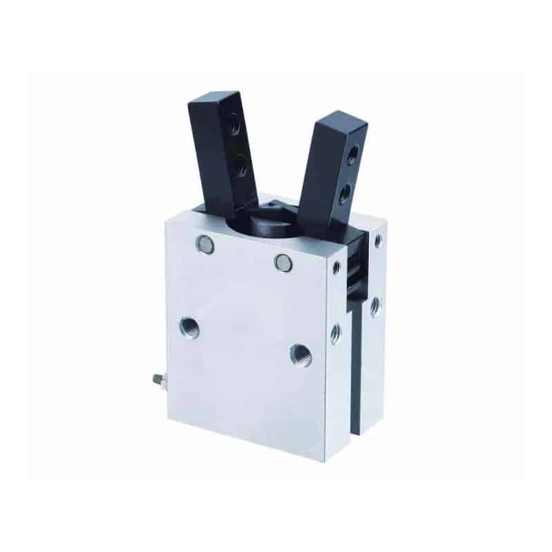
For machine-specific selection, send a marked-up part drawing, mass, contact surfaces, finger length, stroke, available dynamic pressure, cycle timeline, sensor logic, robot acceleration, and safe-state requirement. The XHC parallel pneumatic gripper can then be evaluated against a real load case rather than a generic speed claim.
FAQ About Pneumatic Gripper Pick-and-Place Efficiency
The two most reusable limits in this workflow are SMC’s 5-to-10-times-workpiece-weight grip guideline and CAGI’s 10% system pressure-drop recommendation (SMC, 2025; CAGI, 2026). Neither replaces measurement at the actual gripper during the production cycle. Use them as screening thresholds, then test the fingers, valve, tubing, sensor window, and robot acceleration under production conditions.
What is included in pneumatic gripper cycle time?
Complete gripper cycle time includes PLC output, valve switching, tube filling, jaw motion, sensor response, PLC input processing, transfer, release, and any recovery delay. SCHUNK specifically excludes valve, hose, and PLC delays from its jaw movement figures, so a catalog open-close value should not be used as the complete station estimate.
How much grip force should a pick-and-place gripper have?
SMC recommends at least 5 to 10 times workpiece weight for the cited collaborative-robot gripper family, with more allowance for greater acceleration or impact. Final force still depends on friction, finger count, contact geometry, finger length, dynamic pressure, and part damage limits. Validate the selected margin through an actual transfer test.
Why does a pneumatic gripper slow down during production?
Common causes are dynamic pressure sag, restricted tubing or exhaust, valve delay, contamination, misalignment, worn fingers, or a confirmation timeout that no longer matches real motion. CAGI recommends keeping total pressure drop within 10%; measure near the gripper during simultaneous machine demand to identify a local supply problem.
Can a faster sensor shorten the pick cycle?
Faster sensing can help, but only when sensor response is the limiting delay. SMC lists 1 ms or less for one solid-state switch, while its example uses a 0.1-second PLC response to show how controller timing can dominate detection. Timestamp the sensor edge and PLC state before buying a faster device.
When should an electric gripper replace a pneumatic gripper?
Choose electric when programmable width, speed, force, or intermediate positioning removes tooling and recipe-change delays. SMC lists 64 configurable position, speed, and force points for its LEHZ family. Keep pneumatic when the task is a stable two-position cycle and local air, sensing, force margin, and safe-state behavior are already controlled.
Sources and Retrieval Notes
This guide uses seven first-party or standards sources. ISO 4414:2010 was confirmed current in 2021, while ISO 8573-1:2010 remains the published compressed-air purity reference pending revision (ISO 4414, 2021; ISO 8573-1, 2010). Product-specific numbers remain examples, not universal gripper ratings. Recheck each numeric example against the final part number and application conditions.
- SCHUNK, “PZN-plus 300-2-IS technical details,” retrieved 2026-07-17: https://schunk.com/us/en/gripping-systems/centric-grippers/pzn-plus/pzn-plus-300-2-is/p/000000000000303647
- SMC, “RMHm Series Air Grippers,” retrieved 2026-07-17: https://ca01.smcworld.com/catalog/New-products-en/mpv/ES160-7-RMH/data/ES160-7-RMH.pdf
- Compressed Air and Gas Institute, “Working With Compressed Air,” retrieved 2026-07-17: https://www.cagi.org/working-with-compressed-air/
- SMC, “Auto Switch Guide: D-F7NT,” retrieved 2026-07-17: https://www.smcworld.com/catalog/en/actuator/D-AS1-E/7-4-4-AutoSwitch-D_en/data/7-4-4-AutoSwitch-D_en.pdf
- SMC, “Electric Gripper LEHZ,” retrieved 2026-07-17: https://www.smcworld.com/products/subject/en-my/machine/door/el06.html
- Festo, “Get a Handling on Grippers,” retrieved 2026-07-17: https://www.festo.com/media/cms/media/editorial/downloads/Festo_WP_Grippers_2020_EN.pdf
- ISO, “ISO 4414:2010 Pneumatic fluid power,” retrieved 2026-07-17: https://www.iso.org/standard/44790.html
- ISO, “ISO 8573-1:2010 Compressed air purity classes,” retrieved 2026-07-17: https://www.iso.org/standard/46418.html