

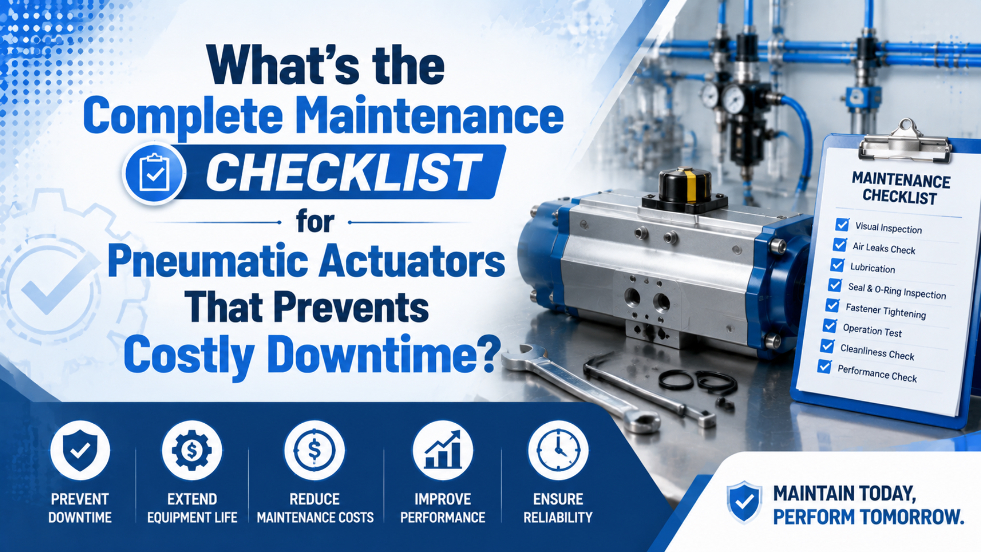
A complete pneumatic actuator maintenance checklist is a closed loop: isolate hazardous energy, compare the machine with a recorded baseline, inspect the actuator and its air supply, correct the fault, and verify the result after restart. ISO 4414:2010 covers pneumatic-system hazards, but it does not prescribe one universal maintenance calendar (ISO 4414, 2010).
This guide covers rod cylinders, rodless cylinders, guided actuators, rotary actuators, and pneumatic grippers. It stays focused on maintenance execution. Use the cylinder and actuator maintenance comparison when the decision is pneumatic versus electric, and the rodless-cylinder preventive checklist for strip, carriage, and guide-specific work.
Key Takeaways
- Control pneumatic and mechanical stored energy before hands-on work.
- ENERGY STAR says leaks can waste 20-30% of compressor output (ENERGY STAR, 2004).
- Set intervals from the model manual, duty, environment, and trend data.
- A repair is complete only after measured verification.
Maintenance trigger is the earliest of four events: a manufacturer interval, a cycle or running-hour limit, a measured condition crossing its control limit, or a change to the machine, load, environment, air supply, or repaired component. It is not simply a date.
What Belongs in a Complete Pneumatic Actuator Maintenance Checklist?
ENERGY STAR reports that compressed-air leaks can waste 20-30% of compressor output in many plants. A complete checklist must therefore cover the actuator, valve, tubing, air preparation, mounting, load, controls, and verification record rather than treating a seal kit as the whole maintenance program (ENERGY STAR, 2004).

Use this as the master route, then attach the exact model manual and site limits:
| Stage | Minimum task | Evidence to record |
|---|---|---|
| Before work | Identify pneumatic, mechanical, electrical, gravity, spring, and process energy | Isolation procedure, affected equipment, authorized person |
| Running observation | Listen for leaks, watch motion, check cycle result, review alarms | Sound or video baseline, stroke time, end-position result |
| Locked-out inspection | Check mounting, rod or carriage, seals, guides, stops, tubing, fittings, valve, and sensors | Condition, measurements, photos, fault location |
| Air-system review | Check dynamic pressure, filter condition, drains, regulator, lubrication rule, and point-of-use air quality | Pressure at rest and in motion, differential pressure, contamination finding |
| Corrective action | Repair the root cause before replacing damaged parts | Parts, settings, alignment, air-treatment or routing change |
| Verification | Leak test, cycle under load, check sensors and stops, inspect the product, then release the machine | Post-repair readings, pass criteria, approver, new baseline |
This structure prevents a common mistake: replacing the visible failed part while leaving the cause in place. A worn rod seal may be the result of side load, dirt, corrosion, or rod damage. The seal is evidence as well as a spare part.
For example, if a new rod seal leaks again at the load-side edge, inspect alignment, rod condition, bearing clearance, and mounting witness marks before installing another kit.
Start With Hazardous-Energy Control
OSHA’s general-industry hazardous-energy rule is 29 CFR 1910.147, and OSHA explicitly includes pneumatic energy among the sources that can injure workers during servicing. Maintenance must follow the employer’s machine-specific energy-control procedure, including isolation, dissipation, restraint, and verification before anyone enters the danger zone (OSHA, 2026).
Stopping the PLC or closing one upstream valve is not proof of zero energy. Pressure can remain between a shutoff valve and an actuator. A vertical load can fall after air is vented. Springs, accumulators, vacuum circuits, or trapped process pressure can also move tooling unexpectedly.
Use the authorized site procedure to complete these actions:
- Identify every energy source and the motion each source can create.
- Stop the machine through its normal controls.
- Isolate and lock or tag the approved energy-isolating devices.
- Vent stored pneumatic pressure and verify the gauge or test point is appropriate for the isolated volume.
- Block, pin, lower, or otherwise restrain gravity and mechanically stored loads.
- Verify isolation using the site’s approved test method before hands-on work.
- Restore guards, tools, settings, and personnel clearance before controlled restart.
Never use this article as a substitute for the employer’s energy-control program. The checklist records whether the approved procedure was completed; it does not invent a new lockout procedure for an unknown machine.
What Should Operators Check During Each Shift?
ENERGY STAR’s 20-30% leak-loss range makes a short running observation worthwhile, but an operator route should not require guards to be removed or hands to enter a hazard area. Compare sound, motion, pressure, alarms, and product handling with an accepted baseline while the machine operates normally (ENERGY STAR, 2004).

| Check from a safe position | Normal condition | Create a work order when |
|---|---|---|
| Sound | Exhaust and impact sound match the baseline | A new hiss, scrape, squeal, knock, or repeating pulse appears |
| Motion | Full stroke or rotation completes smoothly at the expected time | Motion binds, hesitates, drifts, bounces, or times out |
| Product result | Part arrives in position without marks, slip, or misorientation | Handling quality changes even though the actuator still cycles |
| Visible tubing and fittings | Tubes remain seated, supported, and clear of abrasion | A tube kinks, rubs, pulls, whitens, cracks, or leaks |
| Mounting and tooling | No new movement, gap, witness mark, or vibration | A fastener backs out or the actuator shifts relative to the load |
| Pressure and alarms | Dynamic reading and fault history stay inside the accepted band | Pressure changes only during motion or the same alarm repeats |
Tag the exact location of a suspected leak. Then quantify it during an approved maintenance window. The pneumatic leak-detection guide covers listening, leak-detection fluid, ultrasonic methods, tagging, and repair verification.
For instance, a cylinder can complete every stroke while its cycle time slowly rises. That trend deserves a work order even when no alarm has appeared.
Avoid turning the shift route into a teardown. If the task needs a guard removed, a fitting touched, a fastener checked with a tool, or a body placed near motion, move it into controlled maintenance under the site’s energy-isolation procedure.
Which Checks Need a Planned Maintenance Window?
CAGI recommends keeping total compressed-air pressure drop from compressor discharge to point of use within 10% of compressor discharge pressure. A planned shutdown should therefore measure the actuator under flow, not only read a static regulator gauge after the machine stops (CAGI, 2026).
Dynamic pressure is the pressure measured while the actuator performs the specified motion under its normal load. It can reveal restrictions that a static gauge does not show.
Begin with the machine’s baseline and model limits. Record measurements before changing pressure, flow controls, cushions, shock absorbers, or sensor positions. Otherwise, a quick adjustment can hide the original failure path.
Mechanical inspection
- Check mounting fasteners, brackets, trunnions, clevises, rod ends, shafts, fingers, and load connections for movement or damage.
- Inspect exposed rods, guide rails, carriage surfaces, strips, wipers, and stops for scoring, corrosion, debris, impact, or uneven wear.
- Check alignment and side load. Look for one-sided seal wear, polished witness marks, bent brackets, and load binding.
- Confirm the load cannot overrun the actuator or strike an unapproved hard stop.
Pneumatic and control inspection
- Measure pressure close to the valve or actuator at rest and during the worst motion.
- Inspect filter bowls, drains, regulators, lubricators where specified, shutoff valves, exhaust silencers, tubing, and fittings.
- Check the valve exhaust for continuous leakage that can indicate valve leakage or air passing an actuator seal.
- Compare extend and retract time, rotary travel time, or grip sequence with the accepted baseline.
- Verify sensors, brackets, cables, connectors, and end-position logic without moving a sensor to mask incomplete travel.
When the symptom appears only under motion, follow the pressure-drop diagnostic path before increasing the regulator setting. Higher supply pressure can increase impact and air use while leaving the restriction untouched.
From our work, separating static and dynamic readings makes maintenance records easier to compare because the technician can see whether the fault exists before flow starts or appears only during motion.
How Do Checks Change by Actuator Type?
ISO 4414:2010 applies safety principles to pneumatic fluid-power systems and their components, so the common route stays system-based. The wear interface still changes with actuator construction. A rod cylinder, rodless carriage, rotary shaft, and gripper jaw require different inspection points even when they share one air supply (ISO 4414, 2010).
| Actuator type | Inspect closely | Failure evidence to preserve |
|---|---|---|
| Rod cylinder | Rod surface, rod seal, bearing, clevis, mounting, cushion, side load | One-sided seal wear, rod scoring, bent mounting, uneven impact |
| Rodless cylinder | Carriage, guide, strip or band, wiper, coupling, support spacing, load moment | Debris under strip, carriage play, guide wear, coupling slip |
| Guided or compact actuator | Guide rods, bearings, plate alignment, tooling moment, parallelism | Unequal guide wear, plate twist, loose tooling, binding near an end |
| Rotary actuator | Shaft or flange play, stops, cushions, rack or vane housing, load inertia | Backlash change, stop impact, incomplete angle, shaft leakage |
| Pneumatic gripper | Jaws, fingers, guide play, pad condition, synchronization, part contact | Asymmetric wear, finger damage, part marks, slip, jaw-position drift |
A broad checklist should never erase these differences. For long-stroke equipment, use the dedicated rodless-cylinder maintenance route. For repeated contamination damage, compare the failed surfaces with the pneumatic-cylinder contamination case study.
The machine interface matters as much as the actuator family. A healthy cylinder can fail early when the load rail binds. A rotary actuator can appear weak when the external stop or process valve torque changes. A gripper seal kit will not correct fingers that apply an offset moment.
How Should Air Quality and Lubrication Be Managed?
ISO 8573-1:2010 defines compressed-air purity classes for 3 contaminant groups: particles, water, and oil. Maintenance should record the required class and measurement point, then inspect filters, drains, piping, and point-of-use condition against that specification rather than describing the supply only as “clean air” (ISO 8573-1, 2010).
The air reaching the actuator may differ from the compressor-room result. Water can collect in a branch. Corrosion or installation debris can appear downstream of a filter. Oil can come from the compressor, an upstream lubricator, assembly grease, or process contamination.
Use the ISO compressed-air quality guide to document all three classes. Then record evidence from the actual point of use:
- Required particle, water, and oil classes.
- Sampling or inspection point.
- Filter grade, differential-pressure condition, and replacement rule.
- Drain operation and any observed water.
- Regulator setting at rest and pressure during motion.
- Lubricator presence, oil type, and setting only when the exact equipment requires it.
Follow the exact actuator and seal manual for lubrication. Do not add oil mist or grease because another machine uses it. Some actuators are designed for non-lube service or permanent grease; others specify a lubricant, quantity, and service point. Mixing these rules can swell seals, attract debris, wash away compatible grease, or contaminate the process.
The FRL reliability guide explains filter, regulator, and lubricator boundaries. Treat an FRL as part of the maintenance evidence, not proof that the actuator automatically receives suitable air.
Which Symptoms Require Shutdown or Planned Repair?
CAGI’s pressure-drop brief uses a 5-7 psig filter differential-pressure trigger and recommends replacement at least every 6 months as general filter guidance. Those figures are not actuator shutdown limits. Use them with the component maker’s instructions and site risk assessment while classifying motion, load, leakage, and structural symptoms (CAGI, 2026).
| Classification | Examples | Response |
|---|---|---|
| Stop and isolate | Uncontrolled movement, load instability, loose structural mounting, bent or deeply scored rod, repeated binding, rising heat, metal contact, damaged guarding | Stop through the approved process, isolate energy, restrain the load, and inspect before another production cycle |
| Planned repair | Stable external leak, slower motion, pressure sag under flow, louder cushioning, sensor drift, worn tubing, growing guide play | Record the baseline difference, assign risk and due date, then repair in a controlled window |
| Monitor against limit | Small stable variation inside the approved control band with no safety, product, or motion consequence | Keep the machine in service only under the site’s monitoring rule and defined escalation limit |
Do not classify every hiss as a seal failure. Air at the valve exhaust can come from normal switching, a leaking spool, a cylinder piston seal, or a connected branch. Isolate the fault path and test it under the approved procedure.
For an isolated branch with known volume, start pressure, end pressure, and elapsed time, the pressure-decay leak-rate calculator can convert the observation into an estimated flow rate. Estimate financial impact only after the leak-rate assumptions are documented.
When Should You Replace Seals, Rebuild, or Replace the Actuator?
Parker’s OSP-P family spans 10-80 mm bore sizes and separates force, load, moment, and cushioning data by configuration. That range illustrates why repair decisions must use the exact model, condition, and load case rather than one seal-life interval for every pneumatic actuator (Parker OSP-P Catalog, 2025).

| Decision | Use it when | Do not proceed until |
|---|---|---|
| Replace the seal kit | Leakage is traced to serviceable seals; rod, bore, shaft, guides, and mounting remain within model limits | Root cause, material compatibility, kit identity, cleanliness, and assembly method are confirmed |
| Rebuild the actuator | Several service parts are worn, but structural and precision surfaces remain serviceable | The manufacturer procedure, tools, measurements, torque values, lubricant, and test criteria are available |
| Replace the actuator | Structural damage, corrosion, scoring, obsolete parts, repeated failure, unsafe repair access, or lost geometry makes repair uncertain | The replacement matches load, moment, pressure, speed, mounting, sensors, environment, and safety function |
Do not throw away the failed parts before the review. Photograph the installed condition and keep seals, wear rings, broken fittings, damaged tubes, or scored components labeled by location. A cut on one side of a seal means something different from uniform hardening or chemical swelling.
The pneumatic-cylinder repair-versus-replacement guide extends this condition screen into cost, lead-time, compatibility, and downtime decisions.
In our experience, the most useful field on a repair record is often “old-part condition.” A line that says only “seal kit replaced” closes the work order. A note that says “rod seal cut on the load side; bracket witness marks present” opens the root-cause investigation.
Our team found that repair reviews become more useful when the failed part, installation position, and measured machine condition stay together in one record.
Maintenance Records That Prevent Repeat Failures
ENERGY STAR describes 6 parts of a leak-prevention program: identification, tagging, tracking, repair, verification, and employee involvement. The same closed loop works for actuator faults. A checklist prevents repeat downtime only when it preserves the baseline, the failed condition, the corrective action, and the measured result after restart (ENERGY STAR, 2004).
Record at least:
- Machine, asset number, exact actuator model, bore or size, stroke or angle, mounting, orientation, and safety function.
- Date, shift, cycle count or running hours where available, technician, and work-order number.
- Normal baseline and current readings for dynamic pressure, stroke or travel time, sensor result, leakage, and product outcome.
- Environment and change history: load, speed, tooling, air supply, cleaning chemistry, temperature, contamination, or control logic.
- Isolation and stored-energy verification completed under the approved procedure.
- Parts changed, old-part condition, measurements, settings, lubricant, cleanliness controls, and root-cause classification.
- Post-repair leak test, loaded motion test, sensor and stop check, product inspection, approval, and updated baseline.
Post-repair verification means comparing the repaired machine with an acceptance limit under the normal load and worst approved motion. Treat it and “machine ran once” as different states. One successful unloaded cycle cannot prove that dynamic pressure, cushion energy, alignment, grip, or product handling has returned to normal.
Trend the record instead of waiting for a calendar date. A gradual stroke-time change, repeated tube abrasion at one location, increasing guide play, or the same seal failing on the same side can reveal a system cause before the actuator stops production.
Conclusion: Use Triggers, Not a Universal Calendar
ISO 8573-1:2010 separates 3 compressed-air contaminant groups, while OSHA 1910.147 requires control of hazardous energy during servicing. A reliable pneumatic actuator checklist connects those system obligations to model-specific inspection, condition limits, root-cause repair, and post-repair verification instead of promising one daily, monthly, or quarterly schedule for every machine (ISO, 2010; OSHA, 2026).
Build the route around four triggers: the manufacturer interval, actual use, measured condition, and a machine or process change. Keep running observation quick and non-invasive. Move hands-on work into controlled maintenance. Preserve failed-part evidence. Then verify the machine under its real load before returning it to production.
That sequence prevents a checklist from becoming paperwork. It turns each inspection into a comparison, each repair into a documented decision, and each restart into evidence that the failure path was actually closed.
FAQs About Pneumatic Actuator Maintenance
CAGI’s 5-7 psig filter differential-pressure guidance and ENERGY STAR’s 20-30% leak-loss range show why maintenance decisions need measured conditions. The 5 answers below separate frequency, lubrication, tools, seal replacement, and downtime prevention without turning general industry figures into universal limits for a specific actuator (CAGI, 2026; ENERGY STAR, 2004).
How often should pneumatic actuators be maintained?
Use the earliest applicable trigger: the exact model manual, a cycle or running-hour limit, a measured condition crossing its site limit, or a change to load, environment, air supply, or components. ISO 4414:2010 provides safety principles, not a universal monthly or quarterly actuator-service calendar (ISO 4414, 2010).
Should every pneumatic actuator be lubricated monthly?
No. ISO 8573-1:2010 separates particles, water, and oil into 3 compressed-air contaminant groups, but it does not require monthly oil addition. Follow the exact actuator and seal manual. Record lubricant type, quantity, and point only when specified; otherwise, extra oil can disrupt a qualified non-lube or permanently greased design (ISO 8573-1, 2010).
What tools are needed for a pneumatic actuator inspection?
The tool set depends on the approved job: energy-isolation devices, load restraints, pressure test points, leak-detection fluid or ultrasonic equipment, timing or position data, mechanical inspection tools, and model-specific seal tools. OSHA 1910.147 still requires trained workers and verified hazardous-energy control before those tools enter the danger zone (OSHA, 2026).
When is seal replacement better than replacing the actuator?
Choose a seal kit when leakage is traced to serviceable seals and the rod, bore, shaft, guides, mounting, and load path remain within the exact model’s limits. Replace or rebuild when structural or precision surfaces are damaged, parts are unavailable, or repeated failure remains unexplained. Preserve the old parts before deciding.
Can preventive maintenance eliminate all pneumatic downtime?
No checklist eliminates every failure. ENERGY STAR’s 20-30% leak-loss range shows that systematic inspection can address a major source of waste, but safe maintenance also needs model limits, condition trends, trained workers, stocked parts, and verification under load. The practical goal is earlier detection and controlled recovery, not an unsupported zero-downtime promise (ENERGY STAR, 2004).
Source Notes and Retrieval Dates
- ISO 4414:2010, general rules and safety requirements for pneumatic systems and components. Retrieved 2026-07-17.
- OSHA Control of Hazardous Energy, pneumatic and other hazardous-energy control under 29 CFR 1910.147. Retrieved 2026-07-17.
- ISO 8573-1:2010, compressed-air purity classes for particles, water, and oil. Retrieved 2026-07-17.
- ENERGY STAR Compressed-Air Leak Tip Sheet, leak-loss range and leak-management program. Retrieved 2026-07-17.
- CAGI Pressure Drop Technical Brief, system pressure-drop and filter differential-pressure guidance. Retrieved 2026-07-17.
- Parker OSP-P Catalog, model-specific bore, force, load, moment, and cushioning data. Retrieved 2026-07-17.