

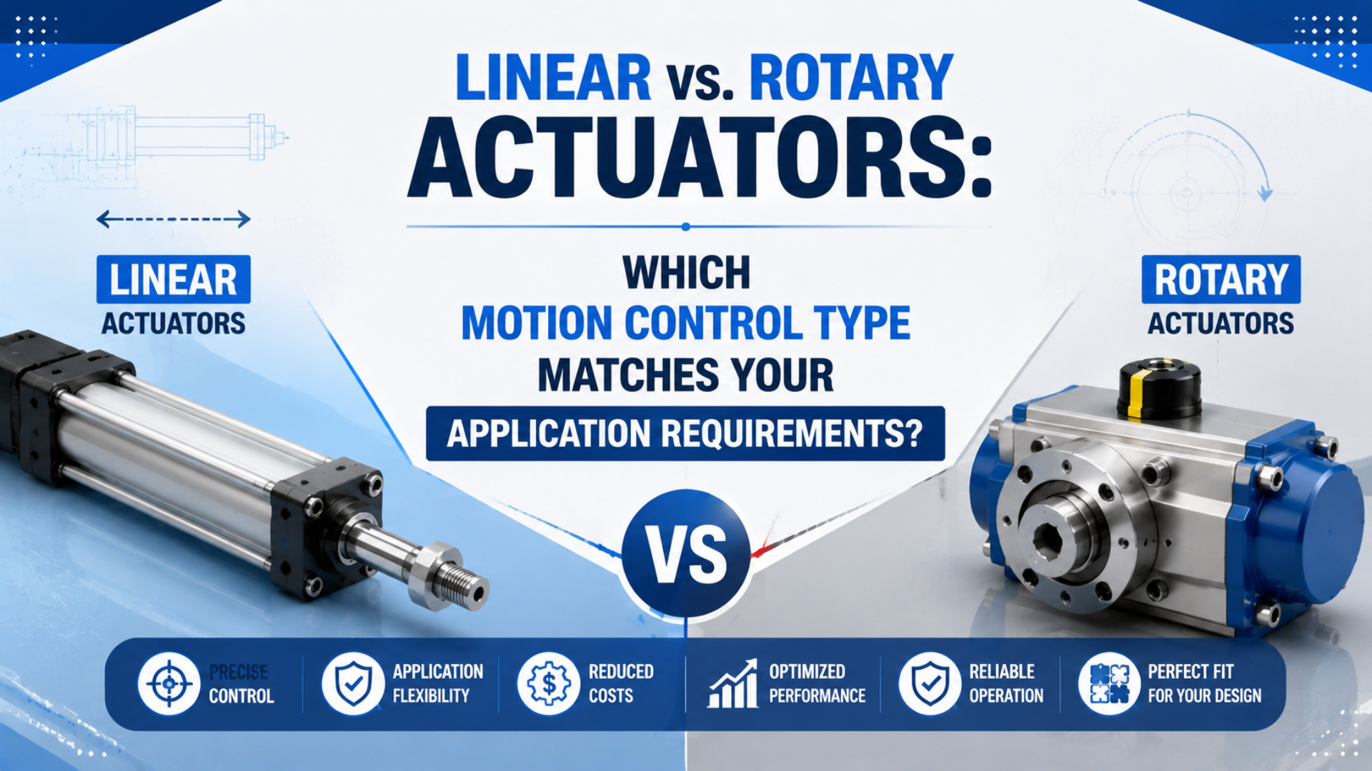
Comparing linear vs rotary actuators begins with the required output path. Choose a linear actuator when the machine output must travel along a straight line. Choose a rotary actuator when the load must turn through a defined angle around an axis. Force or torque, guidance, inertia, stopping method, installation envelope, duty, and control requirements then decide whether a particular actuator will work.
Don’t confuse output geometry with energy source. Pneumatic, hydraulic, and electric devices can all create linear or rotary motion. A linkage can also convert one form into the other. The sound design is the one that produces the required load path with acceptable stress, control complexity, service access, and total cost.
Key Takeaways
- Linear actuators deliver translation; rotary actuators deliver angular displacement.
- ISO 15552 covers 32-320 mm pneumatic-cylinder bores at up to 10 bar.
- SMC lists common pneumatic rotary ranges from 90° to 270°.
- Size force, torque, guidance, inertia, and stopping energy separately.
In our experience reviewing actuator applications, the fastest way to expose a weak concept is to sketch the load path without drawing the actuator. Mark the load, guides or bearings, pivot, end positions, external forces, and available envelope. The required output motion usually becomes obvious before a catalog is opened.
What Is the Real Difference Between Linear and Rotary Actuators?
SMC lists pneumatic rotary actuators with 90°, 180°, 190°, and 270° arcs, all below one complete revolution in those configurations (SMC, retrieved July 17, 2026). A linear actuator instead moves its output along a straight axis. The distinction is output geometry, not the internal mechanism.
A linear actuator is a device whose output translates along a straight axis, normally measured as stroke in millimeters or inches. Its output may be a rod, carriage, slide, table, or belt attachment used to push, clamp, lift, transfer, or eject. A rotary actuator is a device whose output turns through a controlled angle, normally measured in degrees or radians. Its output may be a shaft, flange, or rotary table used to index, flip, tilt, turn a diverter, or operate a quarter-turn valve. Pneumatic, hydraulic, and electric technologies can produce either geometry. If the output must rotate continuously instead of stopping at a defined angle, select and size a motor by running torque, starting torque, rpm, power, and duty rather than treating a limited-angle actuator as a motor.
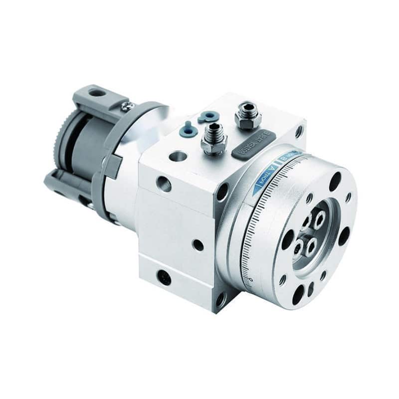
A rotary table places the load around a defined axis. The shaft, bearings, stops, sensors, and permissible kinetic energy are part of the selection.
The guide to pneumatic motors versus rotary actuators examines the continuous-rotation boundary in more detail.
| Output requirement | Start with | Primary sizing variables |
|---|---|---|
| Straight travel between positions | Linear actuator | force, stroke, speed, guide load, stopping distance |
| Rotation to a defined angle | Rotary actuator | torque, angle, inertia, shaft load, stopping energy |
| Continuous shaft rotation | Motor | running torque, starting torque, rpm, power, duty |
| Straight actuator driving a pivot | Linear actuator plus linkage | cylinder force, lever geometry, changing torque, joint loads |
Load Geometry Comes Before Actuator Size
Parker defines rotary demand torque as the sum of load, friction, and acceleration torque, while a static lever converts force to torque through T = F × r (Parker, retrieved July 17, 2026). The load path therefore matters before actuator pressure, bore, or model number enters the calculation.
Start by locating the output reference:
- For linear motion, define the travel axis and the direction of every external force.
- For rotary motion, define the center of rotation and the distance from that axis to each force.
- Identify which bearings, guides, or machine members support the load.
- Mark the center of mass through the complete move.
- Define the hard stops, cushions, shock absorbers, or controlled deceleration zone.
A linear cylinder should normally create thrust, not serve as the machine’s structural guide. Side load and moment should be carried by a guided actuator or external linear bearing unless the product explicitly permits them. Likewise, a rotary actuator shaft should not be assumed to carry an overhung load just because it can generate sufficient torque.
What changes when the center of mass sits 300 mm from the pivot instead of 30 mm? Static load torque increases in direct proportion to the lever arm. The actuator can pass a simple force or torque check and still fail its bearing-load or stopping-energy limit.
Use these renderer-safe first-pass equations:
- Linear force:
F = p × A - Static torque from a force:
T = F × r - Acceleration torque:
T_accel = J × α - Rotational kinetic energy:
E_k = 0.5 × J × ω²
These equations organize the inputs. They do not replace the manufacturer’s force curves, effective-torque tables, shaft-load limits, cushion ratings, or application software.
When Does a Linear Actuator Fit Better?
ISO 15552 covers detachable-mounting pneumatic cylinders with 32-320 mm bores and a maximum rated pressure of 1,000 kPa, or 10 bar (ISO, confirmed 2025). Parker lists OSP-P rodless cylinders from 10-80 mm bore with maximum standard stroke of 6,000 mm (Parker, retrieved July 17, 2026).
Choose a linear actuator when the useful output is straight travel and the load can be supported along that path. Common cases include:
- Moving a product between two stations
- Clamping or pressing against a defined surface
- Lifting with a separate load-bearing guide and safe holding method
- Opening a sliding door or gate
- Ejecting, sorting, stopping, or diverting a product linearly
- Positioning a carriage over a long horizontal stroke
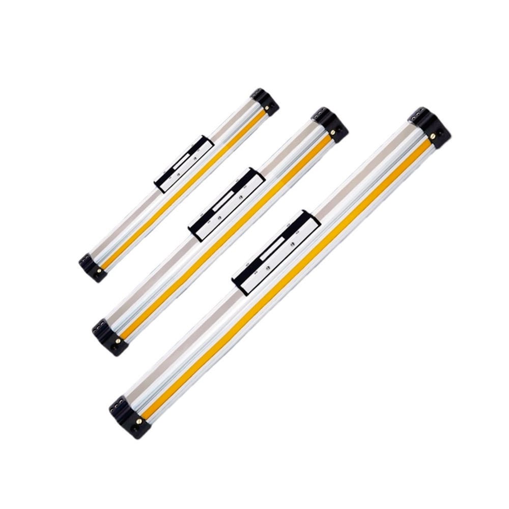
Rodless construction removes the projecting piston rod from the installation envelope. The carriage load, guide moments, tubing, valve flow, cushioning, and external stops still require checks.
For a pneumatic cylinder, extend and retract force are not always equal. A single-rod cylinder has the full piston area on extension and an annular area on retraction. Available dynamic pressure can also fall below the regulator setting because of valve, tubing, fitting, and exhaust restrictions.
Check the load-bearing arrangement separately from thrust. A long rod in compression needs a buckling review. A rodless carriage needs its allowable forces and moments checked against load position and orientation. A vertical axis needs a defined response to pressure loss; cylinder force alone does not establish safe load holding.
For detailed technology branches, use the linear actuator type guide. For a first pneumatic load estimate, use the Cylinder Force Calculator after establishing working pressure at the actuator and the correct effective area.
When Does a Rotary Actuator Fit Better?
SMC groups pneumatic rotary actuators into rack-and-pinion and vane styles, with listed arcs including 90°, 180°, 190°, and 270° (SMC, retrieved July 17, 2026). Parker requires designers to compare demand torque and cushion torque, then verify the actuator can stop the load’s kinetic energy (Parker, retrieved July 17, 2026).
Choose a rotary actuator when the machine needs a defined angular move around a fixed axis:
- Flip a part between two orientations
- Turn a gripper or fixture wrist
- Index a table to one or more stops
- Swing a diverter or access gate
- Tilt a nest for loading or drainage
- Operate a quarter-turn valve
Torque is only the beginning. For a moving load, add resistance torque and acceleration torque. Then check inertia, angular speed, duty, stop method, allowable kinetic energy, shaft radial and axial load, backlash, end-position adjustment, and sensor arrangement.
Parker’s engineering guide gives these relationships:
- Demand torque:
T_demand = T_load + T_friction + T_accel - Acceleration torque:
T_accel = J × α - Rotational kinetic energy:
E_k = 0.5 × J × ω²
A large torque margin does not guarantee a durable stop. Energy rises with the square of angular velocity. Doubling speed produces four times the kinetic energy at the same inertia. That energy must be absorbed by a cushion, bumper, shock absorber, external stop, or controlled motion profile within its rating.
The Rotary Actuator Torque Calculator can organize static, friction, and acceleration torque inputs. For mechanism and series differences, continue with the rack-and-pinion versus vane comparison and the rotary actuator sizing guide.
Motion Conversion Can Be the Better Design
Festo says actuator selection depends on load, precision, dynamic response, environment, and cost rather than one universally better technology (Festo, 2026). A conversion mechanism is therefore justified when it improves packaging, load support, motion profile, maintenance access, or component availability.
“Direct motion” is not a reliability rule. A rack-and-pinion rotary actuator already converts linear piston movement into shaft rotation. Electric screw actuators convert motor rotation into translation. Cranks, cams, toggle linkages, and belts can be sound engineering choices when their geometry is understood and their joints are supported.
Use direct output when it removes unnecessary joints and gives a clean load path. Consider conversion when it provides a useful mechanical advantage, places the actuator outside a hazard or washdown zone, fits the available envelope, creates the required non-linear motion, or lets a standard actuator serve an unusual path.
The tradeoff is geometry-dependent behavior. A cylinder driving a crank does not produce constant output torque through the rotation. Its effective lever arm changes with angle and can approach a dead-center condition. Pin loads, bearing reactions, backlash, joint wear, stop loads, and sensor positions must be evaluated over the complete motion.
| Conversion mechanism | Useful when | Main check |
|---|---|---|
| Cylinder plus crank arm | short angular gate or clamp motion | changing lever arm and dead-center geometry |
| Rack and pinion | compact pneumatic angular output | tooth load, backlash, shaft support, stop energy |
| Motor plus screw | controlled linear position and force | critical speed, buckling, duty, efficiency, alignment |
| Motor plus belt | long, fast linear transfer | belt stretch, guide load, tension, stopping distance |
| Cam or toggle | tailored motion or high end-force | contact stress, dwell, joint force, over-center behavior |
Which Motion Type Fits Common Automation Tasks?
Parker lists OSP-P rodless strokes up to 6,000 mm, while SMC lists pneumatic rotary arcs up to 270° in its standard family overview (Parker, SMC, retrieved July 17, 2026). Those limits illustrate why travel path and envelope should be screened before comparing actuator price.
Use this matrix as a first-pass decision, not a final size selection:
| Application | Likely starting point | Why | Critical follow-up |
|---|---|---|---|
| Long horizontal product transfer | Rodless or guided linear actuator | straight travel and compact total length | guide moments, speed, valve flow, stopping energy |
| Clamp against a fixed datum | Linear cylinder | direct thrust and two clear positions | available force, frame stiffness, safe release |
| Flip a fixture 180° | Rotary table or actuator | load rotates around a defined axis | inertia, bearing load, stop energy, sensor position |
| Quarter-turn process valve | Rotary valve actuator | output angle matches valve stem | breakaway torque, running torque, fail state, interface |
| Swing gate with remote actuator | Linear cylinder plus linkage | packaging or access favors remote placement | torque through full angle, pin load, dead center |
| Continuous mixer | Pneumatic or electric motor | shaft must keep rotating | torque at speed, power, duty, air or energy use |
| Multi-position recipe axis | Electric or servo-controlled actuator | programmable stops and motion profiles | accuracy, repeatability, controls, safety |
Example: Long Transfer Axis
A carriage must move 2,000 mm along a conveyor and remain parallel to the frame. The output is linear. Start with a rodless or guided linear axis, then check carriage moments, guide life, dynamic pressure, target time, end energy, tubing, and sensors. A rotary actuator plus linkage would add a changing motion ratio without solving the guide requirement.
Example: Product-Flipping Station
A fixture must rotate 180° around a supported shaft and dwell at each end. The output is angular. Start with a rotary actuator, then calculate load inertia, resistance and acceleration torque, swing time, bearing loads, cushion or shock-absorber capacity, and end-position confirmation. A linear cylinder remains viable only if linkage packaging or mechanical advantage justifies it.
Example: Offset Diverter Gate
A gate pivots 60°, but the actuator must sit beneath the conveyor for guarding and washdown access. A linear cylinder with a crank link may be the cleaner package. Calculate cylinder force and output torque at several angles, especially where the lever arm is shortest. Then verify joint loads, stops, and fault behavior.
What Data Should an Actuator RFQ Include?
Parker’s pneumatic sizing tool asks for application inputs such as load support, coefficient of friction, valve distance, and operating conditions before returning candidate products (Parker Virtual Engineer, retrieved July 17, 2026). A useful RFQ likewise describes the motion and load instead of requesting only “one linear actuator” or “one rotary cylinder.”
Send a motion sketch and include:
| RFQ input | Linear actuator | Rotary actuator |
|---|---|---|
| Output path | stroke, orientation, number of positions | angle, direction, number of positions |
| Load | mass, external force, friction, guide support | mass, center of gravity, lever arm, inertia, friction |
| Time | extend/retract time and dwell | swing time, dwell, acceleration or stop target |
| Supply | pressure during motion, flow, valve and tube details | pressure during motion, valve and tube details |
| Structure | mounting, guide, side load, moment | shaft support, radial/axial load, flange or table |
| Stop | cushion, shock absorber, external stop | cushion, bumper, shock absorber, external stop |
| Feedback | end sensors, intermediate position, analog feedback | end sensors, adjustable stops, encoder or positioner |
| Duty | cycles per minute, hours per day, life target | cycles per minute, hours per day, life target |
| Environment | temperature, washdown, corrosion, dust, cleanroom | temperature, washdown, corrosion, dust, cleanroom |
| Safety | pressure-loss state, load holding, guarding | fail position, stored energy, guarding, unexpected motion |
Measure pressure while the actuator moves. Static regulator pressure can hide valve and tubing losses. Also state whether the load has its own guides or bearings; otherwise, the supplier cannot judge side load, moment, or shaft-load requirements.
If the unresolved question is energy technology rather than geometry, use the separate cylinder versus electric actuator decision guide. Keeping those decisions separate prevents a linear-versus-rotary comparison from becoming a vague pneumatic-versus-electric debate.
FAQs About Linear vs. Rotary Actuators
Can a linear actuator create rotary motion?
Yes. A cylinder can drive a crank, rack, or linkage to create angular motion. The design must be evaluated across the full angle because the effective lever arm and output torque can change. SMC’s rack-and-pinion products are a familiar example: a linear piston and rack create limited shaft rotation.
Is a rotary actuator the same as a motor?
No. SMC lists common pneumatic rotary-actuator arcs of 90°, 180°, 190°, and 270°, which are limited-angle moves. A motor is selected for continuous shaft rotation using running torque, starting torque, rpm, power, and duty. Don’t use a limited-angle actuator as a continuous mixer drive.
Which actuator type is more accurate?
Neither output geometry guarantees accuracy. Define accuracy, repeatability, resolution, backlash, compliance, and settling time first. Festo notes that precision and dynamic response are technology-selection factors, while the machine’s guides, bearings, feedback, controller, stops, and structure determine what the complete axis can achieve.
Does a rodless cylinder handle side loads better than a rod cylinder?
Not automatically. Parker offers OSP-P configurations with guides and brakes, but each carriage still has published force and moment limits. An unguided rodless cylinder should not be credited with higher side-load capacity merely because it has no projecting rod. Check the exact guide arrangement and load offset.
How much safety factor should I add to force or torque?
There is no universal 25-50% factor for every actuator. Parker states that design factors vary with the application and the designer’s knowledge. Use the product’s selection method, account for pressure variation, friction, acceleration, load uncertainty, duty, and stopping energy, then validate the installed motion.
Conclusion
Linear versus rotary is a geometry decision before it is a product decision. Choose translation for a straight load path, limited-angle rotation for a pivoting load, and a motor for continuous rotation. Then size the real system: force or torque, guides or bearings, stroke or angle, speed, inertia, stopping method, environment, controls, and safety state.
Conversion mechanisms are not inherently inferior. They are appropriate when they improve packaging or mechanical advantage and when the changing geometry is calculated. A clear load-path sketch and complete RFQ will prevent more selection errors than a generic claim that one actuator type is stronger, more precise, or more reliable.
Sources
- International Organization for Standardization. ISO 15552:2018, pneumatic cylinders with detachable mountings. Confirmed February 2025. Retrieved July 17, 2026.
- Parker Hannifin. OSP-P Rodless Cylinders. Retrieved July 17, 2026.
- Parker Hannifin. Pneumatic Actuator Products: Rotary Actuator Torque Requirements. Retrieved July 17, 2026.
- Parker Hannifin. Virtual Engineer pneumatic sizing and selection tool. Retrieved July 17, 2026.
- SMC Corporation of America. Rotary Actuators. Retrieved July 17, 2026.
- Festo. Pneumatics or electrics? How to make the right choice. Published April 8, 2026. Retrieved July 17, 2026.
- AutomationDirect. Linear Motion Products video. Retrieved July 17, 2026.