

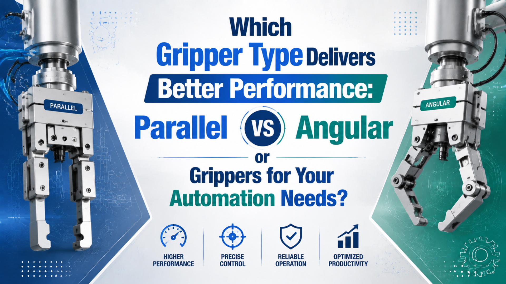
When choosing between parallel or angular grippers, neither type is automatically better. A parallel gripper usually wins when the fingers must keep the same orientation against flat or dimensionally consistent surfaces. An angular gripper is often the better fit when the fingers need to swing clear of a nest, fixture wall, or loading path.
Application geometry decides the result.
That distinction sounds simple, yet it prevents a common specification error: comparing catalog force or body width before drawing the actual contact points. SMC’s model-selection process checks gripping force, external force on the fingers, and gripping-point position as three separate steps (SMC, 2025).
Key Takeaways
- Parallel jaws preserve finger orientation; angular jaws rotate through an arc.
- SMC recommends an initial gripping-force range of 10 to 20 times workpiece weight, with more margin for acceleration or impact.
- Compare force at the real contact point, finger length, fixture clearance, sensing, and the safe state after air loss.
Parallel vs Angular Grippers: The Short Answer
Across SMC’s catalog, the standard MHZ2 parallel family covers seven bore sizes from 6 to 40 mm, while MHC2 angular models cover four sizes from 10 to 25 mm (SMC MHZ2, 2025; SMC MHC2, 2024). These ranges show product diversity rather than a universal performance ranking.
Catalog labels do not decide the application.
Choose a parallel gripper when all or most of these statements are true:
- Two opposing flats are available.
- Finger orientation must stay fixed through the stroke.
- One tool must center a controlled width range into a nest, chuck, or gauge.
- Longer tooling or external loads require a guided jaw with published side-load and moment limits at the proposed contact distance.
Choose an angular gripper when the layout gives you a different set of constraints:
- The fingers must swing clear after release.
- A short closing motion is enough, but open-state clearance matters.
- Pivoting avoids a fixture lip, wall, conveyor guide, or adjacent tool during approach and withdrawal.
- The machine layout can accommodate the complete swept envelope, and catalog force can be checked at the real contact radius and jaw angle.
In our experience, if both lists appear to fit, drawing the closed and fully open finger envelopes on the machine layout exposes the real constraint faster than comparing nominal bore sizes. It also gives controls and safety reviewers a common picture of the intended motion.
What Actually Changes Between Parallel and Angular Grippers?
For the MHC2, SMC specifies a 30° to -10° opening and closing range for both fingers, whereas an MHZ2 moves its jaws along a linear guide (SMC MHC2, 2024; SMC MHZ2, 2026). Jaw trajectory is the defining difference in real machine layouts.
A parallel gripper is a jaw actuator whose opposing fingers translate along straight paths. An angular gripper rotates its fingers about pivots. The actuator mechanism may be pneumatic in both cases, but the resulting fingertip path, contact angle, and clearance envelope are different. With parallel motion, the fingertip face can stay square to a flat part throughout the stroke. The geometry stays predictable. Contact is therefore easier to keep consistent across a modest width range, which helps with blocks, plates, trays, machined bodies, and other parts that offer two controlled faces.
Angular jaws rotate. Their fingertip orientation and contact radius change as they move, so the designer must check more than the final closed position. The benefit is clearance: after release, the fingers can rotate away from a nest instead of translating beside it. Useful comparison goes beyond “linear versus rotary” to contact-normal stability versus swept-envelope clearance. That trade matters. Parallel motion tends to preserve the direction of the contact normal. Angular motion gives up some geometric consistency for a different way of clearing the fixture.
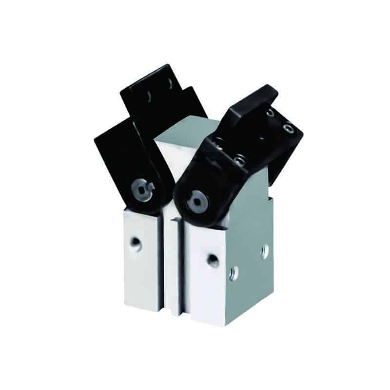
For a broader map of two-, three-, four-finger, toggle, and wide-opening designs, see the guide to different types of pneumatic grippers.
When Does a Parallel Gripper Fit Better?
In one MHZ2 selection example, SMC calculates 24 N per finger at 0.4 MPa with a 30 mm gripping-point distance for an MHZ2-16 configuration (SMC, 2025). Parallel-gripper force depends on both pressure and contact distance, not just bore size.
A parallel gripper is usually the first design to evaluate for rectangular parts, controlled outside diameters, gauge loading, and assembly steps that need a stable centerline. Because both jaws travel in opposite straight lines, a synchronized two-jaw model can center a part while keeping the finger faces aligned. That does not make every parallel gripper equally precise. Guide construction, jaw play, tooling stiffness, sensor resolution, part tolerance, and robot or slide positioning all contribute to process repeatability. A catalog repeatability number belongs to one series under defined conditions; it is not a guaranteed placement tolerance for the complete cell.
Long fingers need special attention. A SCHUNK PGB 100 product page lists 395 N closing force at a finger length of 0 mm and a maximum permissible finger length of 100 mm (SCHUNK, 2026).
Those are different limits.
In our experience, overlong tooling causes more selection failures than insufficient nominal bore because it changes the moment applied to the jaw guide.
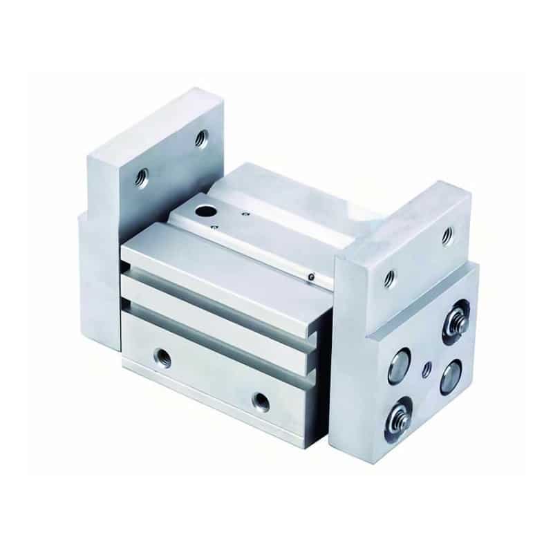
A wide-opening parallel gripper can help when part width changes substantially. It does not remove the need to check guide loads, stroke time, collision clearance, and the pressure available while the machine is cycling.
When Does an Angular Gripper Fit Better?
Within SMC’s range, standard MHC2 angular motion is separate from 180° families such as MHY2 and MHW2; MHW2 covers five bore sizes from 20 to 50 mm (SMC MHW2, 2024). “Angular gripper” therefore covers several motion envelopes, not one geometry.
Clearance drives this choice.
An angular gripper earns its place when the finger swing solves a layout problem. Typical examples include reaching into a pocket, releasing a part between tall fixture walls, clearing a conveyor guide, or opening the fingers away from a machine-tool work zone. Standard-angle and 180° designs should not be treated as interchangeable. A compact angular pneumatic gripper may use a modest pivot range for a short grip-and-release motion. A 180-degree angular gripper creates far more open clearance, but its fingers also need room to sweep through that larger arc.
Angular motion is not a substitute for custom finger design. A contoured fingertip can locate an irregular part on either gripper type. Conversely, a poorly shaped angular finger can push a tapered or fragile part out of position as the contact angle changes. If the station fails only during release, focus on the open path rather than the closed grip. Teams sometimes enlarge a parallel gripper to gain stroke when the real need is to move the fingers out of the fixture’s escape path.
That is geometry, not force.
How Do You Size Grip Force at the Real Contact Point?
For initial sizing, SMC recommends 10 to 20 times workpiece weight and more margin when acceleration, deceleration, or impact is high (SMC, 2025). The catalog also requires force to be read at the actual gripping-point distance, preventing a body-size-only selection.
Pressure at the gripper matters.
For a friction grip with n loaded jaws, a useful first estimate is:
Required force per jaw = m x (g + a) x S / (mu x n)Use the variables below:
| Symbol | Meaning |
|---|---|
m |
Workpiece mass in kilograms |
g |
Gravitational acceleration, approximately 9.81 m/s² |
a |
Acceleration in the load direction in m/s² |
S |
Chosen safety factor |
mu |
Conservative friction coefficient at the real contact surface |
n |
Number of jaws sharing the friction load |
The formula gives a load requirement, not a gripper choice.
For example, a 1.0 kg vertical pick with 5 m/s² upward acceleration, mu = 0.20, two loaded jaws, and S = 2 requires about 74 N per jaw before guide-load and pressure-tolerance checks. Surface oil or dust can lower friction, while pad wear and impact may justify a larger margin. Next, open the candidate gripper’s force graph at the actual finger length or contact radius. For an angular model, identify whether the catalog reports force, torque, or gripping moment. Then check the applicable jaw angle. Point-of-use pressure matters too; pressure drop in the pneumatic system can erase a narrow force margin.
A Practical Selection Matrix
Festo’s gripper-sizing tool asks for object mass, surface quality, and gripper-jaw length, then returns as many as three comparison calculations: exact fit, cost-efficient, and high force or torque load (Festo, 2026). That workflow is more reliable than choosing solely from gripper type or nominal force.
| Decision factor | Parallel gripper | Angular gripper | What to verify |
|---|---|---|---|
| Jaw path | Straight, opposing travel | Rotation through an arc | Closed, open, and swept finger envelope |
| Contact orientation | Usually stays constant | Changes with jaw angle | Pad angle at first contact and full grip |
| Typical geometry | Flats, controlled widths, centered loading | Pockets, walls, short-release strokes, swing clearance | Actual contact zones on the part drawing |
| Force data | Usually force per jaw versus pressure and finger length | May be force, torque, or gripping moment versus radius and angle | Catalog definition and measurement point |
| Long tooling | Raises jaw-guide moment | Raises pivot moment and inertia | Allowable load and moment curves |
| Part variation | Stroke must cover the full width range | Angle must cover the contact range | Worst-case part and fixture tolerances |
| Sensing | Open, closed, or intermediate switch positions | Open, closed, or angular-position detection | Whether “closed” proves part presence |
| Air-loss response | Depends on double acting, spring option, check valve, or external retention | Same principle; mechanism alone is not a safety function | Risk assessment and safe state |
| Best reason to select | Stable contact geometry | Better release or approach clearance | The constraint that cannot be solved economically with tooling |
Use the matrix as a screening tool, then compare actual models at the same point-of-use pressure, load case, finger material, and duty profile. Do not compare one manufacturer’s maximum catalog force with another model’s force at a longer contact distance.
What Determines ROI and Reliability?
Festo’s sizing workflow returns up to three solutions, including a cost-efficient option and a high force or torque-load option, after the application inputs are entered (Festo, 2026). That structure captures ROI better than unsupported universal prices, changeover minutes, or maintenance intervals.
Start with the cost of making the gripping task stable:
| Cost area | Include in the comparison |
|---|---|
| Hardware | Gripper body, sensors, valve, fittings, and mounting adapter |
| Fingers | Design, machining, coating, pads, and expected replacement frequency |
| Engineering | Collision checks, robot payload data, commissioning, and safe-state validation |
| Changeovers | Change-part tooling plus the frequency and complexity of product changes |
| Production risk | Missed picks, dropped or marked parts, misloads, and the resulting downtime |
| Service | Maintenance access, seals, switches, spare units, and supplier support |
Cost follows application fit.
Lowest price rarely means lowest cost. Complex fingers can erase the saving when they must work around the wrong jaw path. Conversely, an angular body adds no value when a simple parallel grasp already provides clean access and stable contact. Reliability depends on the full system. ISO 4414:2010 is a 38-page standard covering pneumatic-system and component safety, reliable operation, maintenance, and intended use; ISO confirmed the edition in 2021 (ISO, 2021). OSHA also identifies parts release and gripper-mechanism failure as mechanical hazards in robot systems (OSHA, 2026).
Treat the loss-of-air state as a selection input, not a commissioning detail. If dropping the part creates a hazard, neither “parallel” nor “angular” is the safety answer. The design may need spring assistance, mechanical retention, a check circuit, controlled lowering, guarding, or another measure established by the machine risk assessment.
What Should You Put in the RFQ?
For model selection, SMC requires three explicit confirmations: gripping force, external force on the fingers, and gripping point (SMC, 2025). A useful RFQ supplies the data for all three, plus the motion envelope and failure state that determine whether parallel or angular motion fits.
Send these application details:
| RFQ field | Required information |
|---|---|
| Workpiece | Drawing, minimum and maximum dimensions, mass, and center of gravity |
| Contact | Allowed zones, surface finish, hardness, oil, dust, burrs, and temperature |
| Grip method | Internal or external gripping and the required part orientation |
| Motion | Robot or slide acceleration, speed, cycle rate, and pickup impact |
| Fingers | Proposed length, contact-point distance, pad material, and approximate mass |
| Air supply | Pressure at the valve while the machine is cycling |
| Fixture | Drawing with approach clearance and the full open-finger escape path |
| Detection | Open, closed, intermediate-position, or independent part-present sensors |
| Safe state | Expected response to air loss, emergency stop, and power isolation |
| Service | Environment, maintenance access, life target, and spare-parts support |
Include both the gripping and release positions. In our experience, the most useful RFQs include one marked-up image for each position; a single photo of the closed station can hide the interference that makes an angular path necessary. If you need a model review, attach the checklist and drawings to the application inquiry.
FAQ
Across one manufacturer’s range, MHZ2 parallel grippers cover seven bore sizes while MHC2 angular grippers cover four (SMC MHZ2, 2025; SMC MHC2, 2024). Even one motion family therefore contains many configurations. These answers are selection rules rather than substitutes for a model-specific force and load check.
Can I use the same pneumatic cylinder for both gripper types?
Usually not. Parallel and angular grippers are normally complete actuators with different pistons, guides, cams, racks, or pivots. SMC lists seven MHZ2 parallel bore sizes separately from four MHC2 angular sizes. You may reuse a valve or air supply after checking flow and pressure, but the gripper bodies are not interchangeable finger kits.
Which gripper type requires less maintenance?
There is no universal maintenance winner. SMC rates the MHC2 angular family up to 180 cycles per minute, but that operating limit does not define a service interval. Contamination, jaw load, finger inertia, impact, lubrication policy, cycle count, and access matter more. Compare the manuals and replacement-parts support for the exact models under consideration.
How do I determine the required gripping force?
Start with mass, acceleration, friction, jaw count, and a safety factor. SMC recommends an initial range of 10 to 20 times workpiece weight, then asks users to consider extra margin for acceleration or impact. Finally, verify force at the real finger length and contact point. Use actual pressure and jaw angle rather than a headline catalog value.
Can I retrofit a parallel station with an angular gripper?
Possibly, but treat it as a new end-effector layout. SMC’s process has three checks: gripping force; external finger load; and gripping point. First confirm mounting holes and sensors. Then recheck valve flow and tubing. Finally review robot payload, tool center point, the complete finger sweep, guarding, and the safe state during pressure loss.
Are angular grippers always better for irregular parts?
Not by default. Festo’s sizing workflow uses object mass plus surface quality and jaw length. It can return as many as three solutions. Finger geometry dominates the decision in many irregular-part applications. Choose angular motion when its rotating path improves approach or release, or when it creates better contact in the actual fixture.
Sources and Retrieval Notes
This comparison uses eight primary technical sources plus one demonstration video. Evidence quality matters. The technical set includes SMC catalogs and selection data from Festo and SCHUNK. It also includes ISO 4414 and OSHA robot-safety guidance. Sources were retrieved on July 17 2026. ISO states that its 38-page ISO 4414:2010 edition was last confirmed in 2021 (ISO, 2021).
- SMC, “Parallel Style Air Gripper, MHZ2 Series,” 2025: https://www.smcworld.com/catalog/BEST-5-4-en/pdf/4-p0417-0485-mhz_2_en.pdf
- SMC, “Angular Type Air Gripper, MHC2 Series,” 2024: https://www.smcworld.com/catalog/en/rotary_airchuck/MHC2-E/7-6-3-p0807-0815-MHC2_en/data/7-6-3-p0807-0815-MHC2_en.pdf
- SMC, “180° Angular Type Air Gripper, MHW2 Series,” 2024: https://www.smcworld.com/catalog/en/rotary_airchuck/MHW2-E/6-3-p0711-0723-mhw2_en/data/6-3-p0711-0723-mhw2_en.pdf
- SMC, “Air Grippers Model Selection,” 2024: https://www.smcworld.com/catalog/BEST-Guide-en/pdf/6-3-p0364-0365_375-378-chack_en.pdf
- Festo, “Gripper Sizing,” retrieved 2026: https://www.festo.com/de/en/s/gripper-sizing/
- SCHUNK, “Universal Gripper PGB 100,” retrieved 2026: https://schunk.com/us/en/gripping-systems/parallel-gripper/pgb/pgb-100/p/000000000000300366
- ISO, “ISO 4414:2010,” confirmed 2021: https://www.iso.org/standard/44790.html
- OSHA, “Technical Manual, Section IV, Chapter 4,” retrieved 2026: https://www.osha.gov/otm/section-4-safety-hazards/chapter-4
- YouTube, “MHF2 Series Parallel Pneumatic Gripper,” retrieved 2026: https://www.youtube.com/watch?v=sLcHqzLYHTk