

Rotary actuator drift is not one fault. A shaft that moves after stopping, a target reached differently from each direction, and an angle that changes from cycle to cycle point to different mechanical, pneumatic, or control problems. SMC’s CRA1 manual notes that its single-rack gear backlash is within 1° at the rotation end, yet it still calls for an external stopper when accurate positioning without backlash is required (SMC CRA1 operation manual, accessed July 17, 2026).
The fastest route to a repair is therefore to name the error, reproduce it under controlled conditions, and isolate the load, stop, air circuit, and feedback chain one at a time. If you need mechanism or application background first, read how pneumatic rotary actuators work.
In our experience, the expensive mistake is rarely a missed seal kit. It is changing pressure, stops, sensors, and PLC timing at once, then losing the evidence that could have separated the fault.
Key Takeaways
- Name the error before replacing parts.
- Measure angle from both directions under the same load, moving pressure, dwell, and rotation time.
- SMC specifies a 0.2-1.0 s/90° stable range for several MSQ configurations, but the exact size, load inertia, adjustment, shock-absorber option, and operating pressure control the usable limit.
- Reject universal accuracy claims.
Treat the final angle as the output of a chain: command, valve, pressure and flow, actuator, coupling, load, stop, sensor, and PLC logic. A changed angle tells you the chain failed. It does not identify which link failed.
What Is Actually Drifting?
Classify the symptom before opening the air circuit. SMC’s rotary-actuator maintenance guide lists four basic inspection items: loose set screws, operating state, external leakage, and abnormal rack-and-pinion backlash. Those checks already span mechanical, pneumatic, and motion faults, so the word “drift” is too broad for a work order (SMC Rotary Actuator Maintenance, accessed July 17, 2026).
Use these working definitions:
Static drift is angular movement during a dwell while the command remains unchanged.
Repeatability error is cycle-to-cycle spread when the actuator approaches the same target from the same direction under unchanged conditions.
Backlash is lost motion that produces a direction-dependent angular difference after reversal.
Overshoot is travel beyond the intended angle before the load stops or settles.
| Symptom | Measurement | Likely branches |
|---|---|---|
| Static drift | Angle changes during a fixed dwell after motion stops | Load torque, trapped-pressure decay, valve leakage, internal leakage, brake or lock failure |
| Repeatability error | Final angle varies across identical cycles approached from the same direction | Moving-pressure variation, stop compliance, sensor shift, friction, cushion or shock-absorber condition |
| Backlash or hysteresis | Final angle depends on clockwise versus counterclockwise approach | Gear clearance, key or coupling play, shaft connection, external linkage, stop contact |
| Overshoot or rebound | Angle passes the target, bounces, or settles slowly | Excess speed, load inertia, worn shock absorber, cushion setting, flexible stop or frame |
| Constant offset | Results repeat tightly but remain displaced from the target | Stop adjustment, mounting shift, sensor teach point, fixture datum, PLC offset |
This classification prevents a common false diagnosis. Repeating within a narrow band but missing the drawing target is usually an offset problem, not poor repeatability. A shaft that reverses through a small free angle is backlash, not seal drift.
Ignore catalog adjectives without their test conditions. The relevant acceptance limit comes from the exact model, stop arrangement, load, approach direction, pressure, measurement point, and machine requirement.
Establish a Repeatable Measurement Baseline
Measure at least 20 cycles from each approach direction before changing a setting. The count is a practical screening baseline, not a catalog life test. For context, the SMC MSQ catalog lists stable rotation-time ranges that commonly begin at 0.2 s/90°, showing why speed must remain controlled during any angle comparison (SMC MSQ catalog, accessed July 17, 2026).
Record the conditions that can move the result:
- Exact actuator model and rotation setting.
- Stop type, cushion or shock-absorber option, adjustment position, mounting reference, and the technician who last changed any setting that could alter the final angle.
- Target angle and datum.
- Load mass, center-of-gravity radius, orientation, tooling, process torque, and any recently changed fixture.
- Approach direction and whether the target is an end position or an intermediate hold.
- Pressure at rest, then pressure close to the actuator during the worst simultaneous air demand.
- Rotation time, dwell before reading, cycle rate, measured angle, sensor state, PLC command, alarm, and product result.
Keep the calculations visible and simple:
| Metric | Screening calculation | What it reveals |
|---|---|---|
| Position error | measured angle - target angle |
Direction and size of the miss |
| Repeatability range | highest reading - lowest reading for one approach direction |
Cycle-to-cycle spread |
| Static drift | angle after dwell - angle at dwell start |
Movement while the command is unchanged |
| Directional difference | clockwise mean - counterclockwise mean |
Backlash, stop, or linkage sensitivity |
Use the plant’s approved statistical definition. The range above is only a maintenance screen and cannot replace a drawing tolerance, measurement-system analysis, or validated process-capability method.
NIST describes targeted equipment data, including robot joint and tool-center-position data, as an input to monitoring and diagnostic work. The same principle applies here: an angle reading becomes useful when it is timestamped with command, pressure, direction, and load state (NIST Manufacturing Maintenance Strategies, updated January 3, 2022).
In application reviews, one of the most useful records is a four-column trend: commanded angle, measured angle, moving pressure, and approach direction. The pattern often appears within a few cycles.
Isolate Mechanical Backlash and Load-Side Error
Inspect the load path before blaming the actuator. The SMC CRA1 manual publishes allowable shaft-load values that vary by size and direction, with table values ranging from 29.4 N to 980 N. That spread makes a generic “shaft load is acceptable” statement useless without the exact model and geometry (SMC CRA1 operation manual, accessed July 17, 2026).
After applying the site’s approved energy-isolation procedure and restraining the load, check the full mechanical chain:
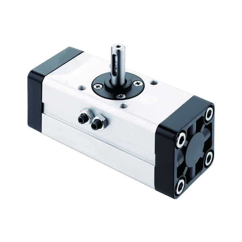
- Start at the mounting bolts and dowels.
- Check brackets and witness marks around the body, especially after a collision or tooling change.
- Measure table or shaft play. Inspect the key, keyway, clamping hub, coupling, and driven shaft rather than judging them by sight alone.
- Clean and inspect external stops for loose fasteners, dents, wear, flex, and unequal contact.
- Review bearing play, radial or thrust load, misalignment, the load center of gravity, and process resistance such as a stiff valve stem or hose torque.
Run a directional test. Approach the target clockwise, then counterclockwise. A stable separation between the two means is strong evidence of clearance or stop behavior, while random scatter within either direction points elsewhere.
Do not assume that a new actuator will remove external play. A worn coupling, loose fixture, flexible frame, or damaged machine stop will reproduce the same error with a replacement unit. The rack-and-pinion and vane comparison explains why construction matters, but the machine interface still has to be tested.
Does the Error Appear Only While the Actuator Moves?
If error grows when other equipment cycles, measure dynamic pressure near the valve or actuator. CAGI says a well-designed compressed-air system should have no more than 10% pressure drop between compressor discharge and any point of use, and it identifies piping, fittings, filters, and dryers as sources of resistance (CAGI Pressure Drop Technical Brief, accessed July 17, 2026).
A static gauge can look normal. It does not prove that pressure stayed stable during acceleration, deceleration, or simultaneous plant demand.
Use two gauges or transducers when possible: one upstream of the valve and one close to the actuator. Compare all three traces: pressure, angle error, and rotation time.
| Observation | Likely interpretation | Next check |
|---|---|---|
| Upstream and actuator pressure both fall | Branch or plant supply limitation | Filter differential pressure, regulator capacity, header demand, receiver and branch sizing |
| Upstream pressure holds but actuator pressure falls | Local restriction | Valve flow, silencer, fitting, tubing diameter, kink or blocked speed controller |
| Pressure holds but time and angle vary | Mechanical friction, stop, cushion, sensor or valve switching | Reversal test, exhaust test, command timing and load inspection |
| Error appears only with another machine event | Shared supply or control interaction | Timestamp both events, isolate branches, check voltage and PLC sequence |
Diagnose pneumatic pressure drop before raising the regulator. Higher pressure can worsen impact, increase air use, and leave the actual restriction untouched.
ISO 8573-1 classifies compressed-air purity by particles, water, and oil. Use the required class and sampling point for the real machine instead of describing the supply as simply “clean” (ISO 8573-1, 2010). Record all three contaminant classes rather than a generic pass or fail.
Can Internal Leakage Move the Load?
Leakage becomes a drift mechanism only when the circuit and load allow motion. SMC links internal leakage to seal damage from foreign matter or unsuitable oil, while its rotary troubleshooting table treats external leakage, shaft bending, bearing damage, valve malfunction, filter clogging, and regulator failure as separate causes (SMC Rotary Actuator Maintenance, accessed July 17, 2026).
First identify the operating state when the angle changes:
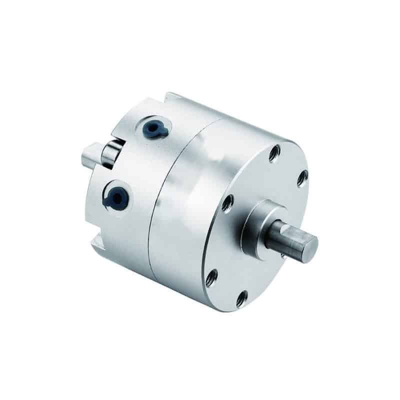
- At a hard external stop: the intact stop should define the angle.
- At an intermediate pneumatic hold: valve leakage, seal bypass, changing chamber pressure, or external load torque can move the shaft over time.
- With supply isolated: interpret movement from the approved circuit diagram, trapped volumes, gravity, spring force, process torque, check-valve state, valve center condition, and every permitted exhaust path. Motion alone cannot identify which component passed air.
- Only after reversal: run the directional test before assigning a cause.
Listen at the valve exhaust only as a locating clue. Exhaust flow can come from normal switching, a leaking valve spool, air crossing an actuator seal, or another connected branch. Isolate components using the manufacturer’s approved procedure and rated test equipment. Do not loosen a fitting or disconnect a pressurized line to “see where the air goes.”
When contamination is found, correct the source first. Inspect drains, filter condition, differential-pressure history, downstream corrosion, assembly debris, incompatible lubricant, prior service work, and the point-of-use air specification. A fresh seal in the same dirty circuit will fail again.
Check Sensors and the Control Architecture
A position switch confirms that its sensing target entered a switching zone; it does not automatically prove the output table reached a calibrated angle. SMC’s MSQ external-shock-absorber versions allow ±3° adjustment at each rotation end, so a sensor, stop, and commanded angle must be documented as three separate settings (SMC MSQ catalog, accessed July 17, 2026).
Check the signal chain in sequence:
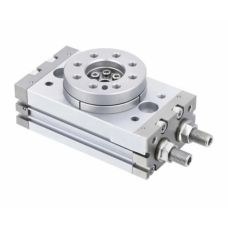
- PLC output changes when expected.
- Solenoid voltage and manual override behavior match the valve specification.
- Valve shifts and remains in the intended state.
- The actuator reaches the physical stop.
- The sensor changes state at the intended location and stays mechanically secure.
- PLC input filtering, debounce, timers, interlocks, recipe selection, and teach values must reject an early signal, preserve the required dwell, and record a timeout before the next machine step begins.
Mark the sensor bracket and stop before adjustment. If both are moved during troubleshooting, the original relationship is lost and the root cause can be hidden.
For two-position motion, end stops usually define the angle and sensors confirm arrival. Intermediate positioning needs a control architecture designed for it, such as an appropriate center-position module or closed-loop system with position feedback and a proportional valve. The feedback-sensor integration guide covers that boundary.
Festo describes fixed stops and cushioning as contributors to repetition accuracy in rotary drives, while sensing remains a separate option. That distinction supports the diagnostic rule: a sensor signal, mechanical stop, and measured output angle are related, but they are not interchangeable evidence (Festo Rotary Drives, accessed July 17, 2026).
If the process needs several programmable angles, a controlled motion profile, or continuous position reporting, compare servo-pneumatic and electric rotary solutions instead of expecting a basic two-position circuit to behave like a servo axis.
Are Speed and Stop Energy Creating a False Positioning Fault?
Excess stopping energy can look like poor accuracy because the table rebounds, the stop flexes, or the adjuster moves. For MSQ sizes 10-50 with shock absorbers, SMC lists kinetic-energy values from 0.161 J to 1.82 J by size and absorber option, with a 0.2-1.0 s/90° stable operating range (SMC MSQ catalog, accessed July 17, 2026).
Watch one full motion at reduced speed from a safe position. If the final angle becomes stable as speed falls, inspect stopping energy, cushion or shock-absorber condition, stop rigidity, exhaust control, and load inertia before changing sensors.
Check these factors separately:
- Start with load moment of inertia.
- Record rotation time and angular deceleration near the stop, not just total cycle time.
- Compare catalog allowable kinetic energy for the exact actuator and stop option with the real load case.
- Inspect shock-absorber stroke, adjustment, temperature, leakage, and replacement condition. A worn absorber may still look intact.
- Watch stop contact and frame movement through first impact and rebound.
- Finish with meter-out control and every exhaust restriction that changes deceleration, including silencers, undersized fittings, long tube runs, quick-exhaust devices, and shared valve manifolds operating during the same machine event.
The MSQ catalog states that shock absorbers are consumable and should be replaced when energy absorption has deteriorated and full-stroke readjustment no longer removes bounding. That is a condition-based decision, not a universal calendar.
If torque or inertia margin is uncertain, use the Pneumatic Rotary Actuator Torque Calculator as a screening aid, then verify torque and allowable energy against the exact catalog. The full rotary-actuator sizing guide keeps sizing separate from this diagnostic procedure.
When Should You Adjust, Repair, or Replace the Actuator?
Use measured restoration criteria, not a fixed percentage of purchase price. The CRA1 manual recommends annual inspection and seal replacement every three years for that specific series, while also directing broken shaft, pinion, rack, or bearing cases back to SMC for repair and operating-condition review (SMC CRA1 operation manual, accessed July 17, 2026).
Apply the decision to the identified fault:
| Decision | Appropriate when | Required verification |
|---|---|---|
| Adjust | Stop, sensor, flow control, cushion, mounting, or PLC value is incorrect but components remain serviceable | Repeat the same loaded angle test from both directions |
| Repair | Approved service parts exist and shaft, bore, gear, bearings, and mounting interfaces remain inside model limits | Leak test, loaded cycling, angle trend, stop behavior, and sensor sequence |
| Replace | Body or non-serviceable parts are damaged, repair is unsupported, repeated wear shows an unresolved design problem, or verified performance cannot meet the machine limit | Confirm replacement torque, energy, shaft load, angle, interface, circuit, environment, and feedback |
| Redesign | The actuator repeatedly exceeds load, energy, pressure, accuracy, or control-architecture limits | New application review and acceptance test under worst operating conditions |
Age alone is not a failure mode. A five-year-old actuator inside its measured limits may remain serviceable; a new actuator exposed to misalignment or excessive stop energy can fail quickly.
Use the broader pneumatic actuator maintenance checklist for isolation, inspection records, air preparation, and repair verification. This article supplies the rotary-positioning branch of that maintenance route.
FAQs About Rotary Actuator Drift and Positioning
The most common questions concern hold position, acceptable error, air pressure, sensors, and replacement. One catalog number shows why generic answers fail: SMC states that CRA1 single-rack backlash is within 1° at the rotation end, but a different mechanism, stop package, and test method can produce a different limit (SMC CRA1 operation manual, accessed July 17, 2026).
Can worn seals cause a pneumatic rotary actuator to drift?
Yes. Leakage can change chamber pressure when the load is free to move and no sound external stop defines the angle. Before replacing seals, confirm valve state, load torque, stop contact, and the permitted leakage path. Seal bypass is only one branch.
What positioning accuracy should a replacement rotary actuator achieve?
Use the replacement model’s stated test conditions and the machine’s acceptance limit. There is no defensible universal ±0.1° value for all pneumatic rotary actuators. Mechanism, direction of approach, stop type, load, pressure, speed, coupling, sensor method, and measurement location all affect the observed result.
Why is the angle correct at low speed but wrong at production speed?
That pattern points toward stopping energy, pressure loss, exhaust restriction, stop flexibility, or shock-absorber condition. SMC lists a 0.2-1.0 s/90° stable range for several MSQ versions and warns that exceeding allowable kinetic energy can damage internal parts. Check the exact model rather than copying that range to every actuator.
Can a reed switch measure exact rotary position?
Not by itself. A reed or solid-state switch usually confirms that a magnetic target entered its sensing zone. The mechanical stop defines a basic end position, while an encoder or other calibrated position sensor is needed when the controller must measure angle continuously. Also check bracket movement and PLC input timing.
Should an actuator be replaced when repair reaches 60% of replacement cost?
No engineering standard establishes that percentage. The decision must include root cause, approved parts, non-serviceable damage, downtime, safety, recurrence risk, and verified post-repair performance. Replace or redesign the unit when it cannot meet the documented load, energy, angle, interface, environment, or control requirement.
A Practical Decision Rule
The decision rule is simple: reproduce the error, classify it, isolate one branch at a time, and retest under the original load. CAGI’s 10% system pressure-drop guidance and SMC’s model-specific stop, energy, and backlash limits show why a single static gauge or universal accuracy number cannot close the diagnosis (CAGI, accessed July 17, 2026; SMC, accessed July 17, 2026).
A successful repair should produce the same result from both approach directions, during the worst simultaneous air demand, after the specified dwell, and across the required number of cycles. Save that data as the new baseline. The next investigation will start with evidence instead of adjectives.